Article

Working Fluid Selection for Organic Rankine Cycle Using Single-Screw Expander

1
MOE Key Laboratory of Enhanced Heat Transfer and Energy Conservation, College of Environmental and Energy Engineering, Beijing University of Technology, Beijing 100124, China
2
Beijing Key Laboratory of Heat Transfer and Energy Conversion, College of Environmental and Energy Engineering, Beijing University of Technology, Beijing 100124, China
*
Author to whom correspondence should be addressed.
Energies 2019, 12(16), 3197; https://doi.org/10.3390/en12163197
Submission received: 6 July 2019 / Revised: 15 August 2019 / Accepted: 15 August 2019 / Published: 20 August 2019

Abstract

:
The organic Rankine cycle (ORC) is a popular technology used in waste heat recovery and medium-low-temperature heat utilization. Working fluid plays a very important role in ORC. The selection of working fluid can greatly affect the efficiency, the operation condition, the impact on the environment, and the economic feasibility of ORC. The expander is a key device in ORC. As a novel expander, single-screw expanders have been becoming a research focus in the above two areas because of their many good characteristics. One of the advantages of single-screw configurations is that they can conduct a vapor–liquid two-phase expansion. Therefore, in order to give full play to this advantage, a working fluid selection for ORC using a single-screw expander was conducted in this paper. Three indicators, namely, net work output, thermal efficiency, and heat exchange load of condenser, were used to analyze the performance of an ORC system. Through calculation and analysis, it can be seen that an ORC system that uses a single-screw expander and undergoes a vapor–liquid two-phase expansion is able to obtain a higher thermal efficiency, higher net work output, and a smaller heat exchange load of the condenser. Regardless of whether isentropic efficiency of the expander is considered or not, cis-butene may be the best candidate for working in subcritical cycles. HFO working fluids are more suitable for working in transcritical cycles, and HFO-1234ze(E) may be the best.

1. Introduction

Renewable and sustainable energy utilization and recovery of low-grade waste heat are two measures for alleviating the global energy crisis and for solving the environmental problems caused by the consumption of traditional energy sources. The organic Rankine cycle (ORC) has been widely studied and adopted in the two fields mentioned above. Working fluid selection plays a decisive role in an ORC, because it can greatly affect thermodynamic performance, working conditions, impact on the environment, and economic feasibility [1,2]. Basically, organic working fluid can be classified into three categories, on the basis of the slope of the saturated vapor curve in a T-s diagram. These are: dry fluid, with a positive slope; wet fluid, with a negative slope; and isentropic fluid, with a vertical slope [3]. From the viewpoint of thermodynamic performance, dry and isentropic working fluids are more appropriate for ORC systems, because after isentropic expansion, they are in superheated and saturated states, respectively. Therefore, damage to the expander caused by wet vapor can be avoided. As a result of environmental concerns, the CFCs and HCFCs that dominated organic working fluids from 1931 until the early 1990s have been and are being phased out, respectively. Nowadays, HFO working fluids are drawing increasing attention. R1234yf and R1234ze are two typical HFO working fluids that have recently been studied and are being used frequently [4,5,6,7]. As far as the economic performance of a practical ORC system is concerned, the investment required by the heat exchanger accounts for the largest proportion, followed by that for the expander, and the working fluid accounts for the third [8]. The first two investments are significantly influenced by the characteristics of the working fluid.
The expander is a critical device in an ORC system, because it determines the thermodynamic performance of the ORC system, and its cost ranks second in the total system investment [8]. Expanders, can generally be categorized into two types: the turbo type and the positive-displacement type. Turbo expanders are normally suitable for large-scale ORC systems [9,10]. However, they might not be favorable for small-scale ORC units [11]. Positive-displacement expanders, such as rolling piston expanders, scroll expanders, and single-screw expanders, are good substitutes for turbo machines due to their relatively high efficiency, high pressure ratio, low rotational speed, and tolerance of two-phase fluids [9]. Among the above three types, scroll expanders constitute a research hotspot. However, their power is normally lower than 3.5 kW. Lemort et al. tested four volumetric expanders (scroll, screw, piston and roots) at <5 kW in a small-scale organic Rankine cycle system with R245fa as the working fluid. They found that the scroll expander showed the highest isentropic efficiency [12]. In contrast, single-screw expanders seem more promising when the output power is higher than 3.5 kW [11]. Furthermore, screw expanders are more technically mature than scroll and piston expanders [13]. The single-screw configuration was first invented in the 1950s, and has mainly been employed in compressors [14,15]. Nowadays, this configuration is widely used in the design and manufacture of expanders. Compared with rolling piston expanders and scroll expanders, single-screw expanders have many advantages, such as balanced load of the screw, long service life, high volume efficiency, good performance at partial load, low leakage, low noise, low vibration, and simple configuration [11].
All of these advantages have attracted many researchers to carry out relevant study on the design and application of single-screw expanders. The group of Lemort and Quoilin modified a standard compressor into an 11 kW single-screw expander and used it to conduct an experimental study. The maximum expander isentropic efficiency and the generated power were, respectively, 64.78% and 7.8 kW [16]. Ziviani et al. carried out a comprehensive review of the geometry modeling of single-screw machines. In their review, the main geometric parameters and constraints were discussed, and the limitations of the existing methodologies were highlighted. An 11 kW single-screw expander was considered in carrying out the calculations [17]. Giuffrida improved the semi-empirical modeling of single-screw expanders for small organic Rankine cycles, and the application of the proposed modeling to a single-screw expander resulted in mean absolute percentage errors of 0.69%, 1.77% and 0.33% with respect to mass flow rate, electric power output and exhaust fluid temperature, respectively [18]. Wang et al. established a theoretical model for analyzing the internal leakage of single-screw expanders [19], and studied the influence of clearance height on the performance of single-screw expanders in small-scale organic Rankine cycles [20]. They found that an appropriate fitting gap adjustment was a necessary measure for improving single-screw expander performance. The volumetric efficiency decreased by 4.42–7.7%, and the power output increased by 0.02–0.11 kW, when the fitting clearance height was between 0.03 mm and 0.09 mm. They also found that clearance height had a great influence on the expander performance. The volumetric and isentropic efficiency decreased slowly at first, and then more quickly with increasing clearance height at a given rotation speed.
Experimental studies on single-screw expanders initially used compressed air as the working fluid. Lu et al. established a compressed air refrigeration system using a single-screw expander with 175 mm diameter [21]. Higher than 65% adiabatic efficiency for single-screw expander was achieved and a more than 70 °C temperature drop could be obtained in the experiment. He et al. conducted an experiment to study the influence of intake pressure on the performance of a 175-mm-diameter single-screw expander working with compressed air [22]. They found that the highest overall efficiency could reach 55% or so, that the greatest torque reached nearly 100 N·m, that the highest power output amounted to about 22 kW, and that the lowest gas consumption was about 60 kg/kWh.
Subsequently, some work was done on single-screw expanders employed in ORC systems for the purposes of waste heat recovery. Zhang et al. developed a single-screw expander with a 155-mm-diameter screw and established an ORC system with R123 as the working fluid for waste heat recovery from the exhaust of a diesel engine [23]. They achieved a maximum power output of 10.38 kW. The highest ORC efficiency and overall system efficiency were 6.48% and 43.8%, respectively, which were achieved at a diesel engine output of 250 kW. Yang et al. conducted similar work using R245fa as the working fluid [24]. They presented a vehicle diesel engine–ORC combined system. They found that when the diesel engine speed was 2200 r/min and the diesel engine torque was 1200 N·m, the power output of the combined system reached its maximum value, at approximately 308.6 kW, which is 28.6 kW higher than the power output of the diesel engine.
Based on the reviewed papers, it can be seen that thermodynamic cycle analysis has previously generally been based solely on the use of single-screw expanders as an alternative to other types of expanders. Working fluid selection has also typically been based on the traditional organic Rankine cycle model. Wajs et al. presented a prototype for a domestic ORC micropower plant that used a gas boiler as an autonomous source of heat. They found that a domestic gas boiler was able to provide the saturated/superheated ethanol vapor and steam necessary to act as working fluids for ORC and RC systems, respectively [25]. Dariusz Mikielewicz and Jaroslaw Mikielewicz proposed a thermodynamic criterion for working fluid selection, for both the subcritical and the supercritical organic Rankine cycle. They chose R123 and R141b for small-scale domestic CHP applications [26]. They also suggested an Organic Flash Cycle (OFC) that would potentially be able to improve the utilization efficiency of the heat source. In their study, the results showed that the single flash OFC achieves better efficiencies than the optimized basic ORC [27]. R245fa and SES36 were selected by the group of Lemort and Quoilin in a test rig equipped with a single-screw expander that had been modified from a standard compressor with a shaft power of 11 kW. The reason for the selection of this working fluid selection was simple: null ODP (ozone depletion potential). This is a well-known factor in the power industry, especially among ORC manufacturers [28]. Tolerance of vapor–liquid two-phase expansion, which is an important characteristic of single-screw expanders, has not been considered or utilized in previous analysis and research. The selection of working fluids that match the characteristics of vapor–liquid two-phase expansion in single-screw expanders has not been carried out, although in a review paper, White et al. compared the power output predicted by two different models of n-pentane, n-hexane, and isopentane within partially evaporated and a superheated cycles [29]. The selection of the expander and the working fluid are strongly interconnected. Therefore, in this paper, two ORC models—a subcritical cycle model and a transcritical cycle model—that are able to give full play to the advantages of vapor–liquid two-phase expansion are presented. Moreover, working fluid selection is conducted for ORC using a single-screw expander on the basis of three indicators, namely, net work output, thermal efficiency, and heat exchange load of condenser.

2. Ideal Subcritical Cycle Model

Liu et al. stated that dry or isentropic working fluids were the most appropriate for ORC systems. This is because these two types of working fluid are superheated following isentropic expansion; thereby, any damage to the turbine blades caused by liquid droplets can be avoided [3]. They also concluded that a superheated apparatus was not required. This conclusion was with reference to a turbo-type expander. However, for single-screw expanders, which are able to tolerate vapor–liquid two-phase expansion, different conclusions may be drawn. Figure 1 depicts the configuration of a single-screw expander. Its working processes are depicted by Figure 2.
It should be noted, here, that although single-screw expanders are able to carry out vapor–liquid two-phase expansion, wet working fluids have still not been adopted in ORC systems with single-screw expanders as a result of three considerations. First, there is no consensus regarding the minimum dryness of the working fluid used with single-screw expanders. Second, the expansibility of vapor-phase working fluids is much better than that of liquid-phase working fluids. Last, low- to medium-grade thermal energy is “precious”, and it cannot be wasted on overheating wet working fluids. Therefore, in the following calculation and analysis, only dry and isentropic working fluids are considered and included.

2.1. Working Conditions of Expander Inlet are Known

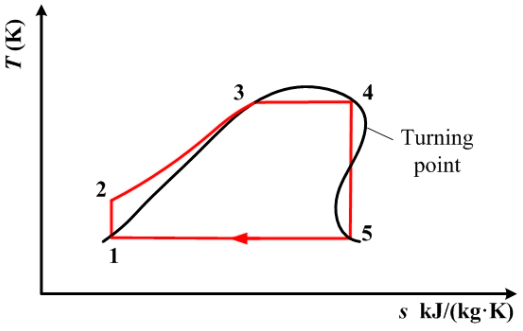
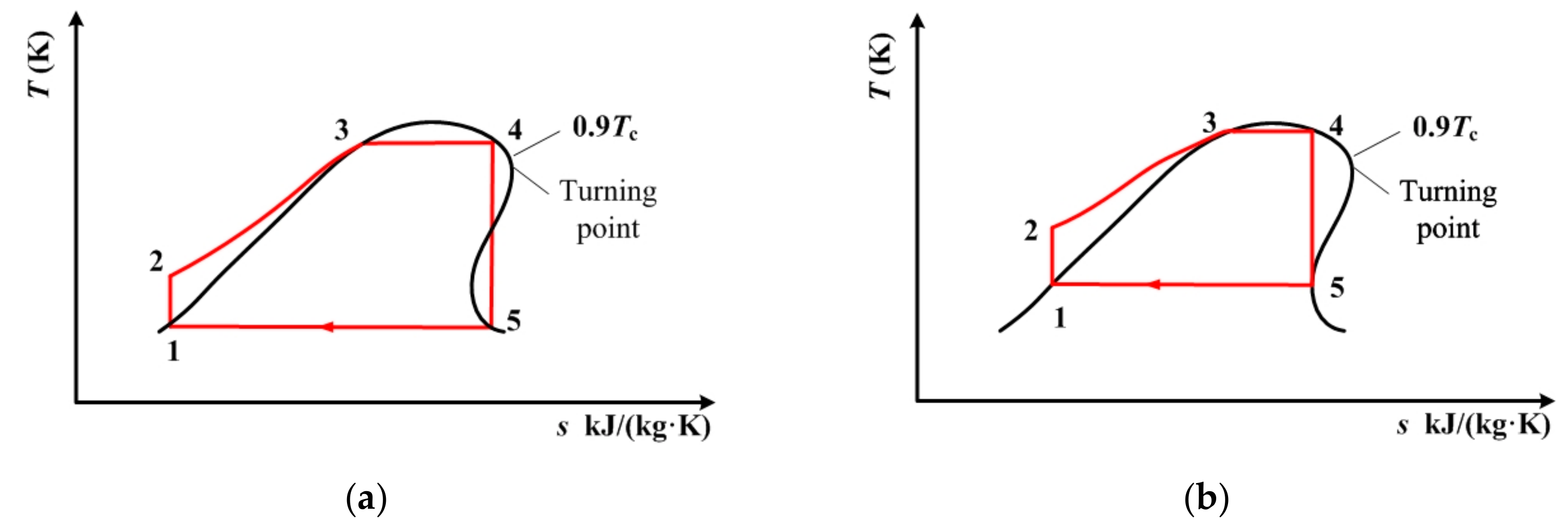
2.1.1. Thermodynamic Setting and Description

In a T-s diagram, a significant difference between dry (or isentropic) fluid and wet fluid is the existence of a point at which the entropy value reaches the maximum on the saturated vapor curve ranging from the normal boiling point to the critical point. This point is located near the critical point, and is defined as the turning point [30]; other details about the role of this point can be found elsewhere [31]. The turning point temperature is the limit of subcritical ORC when adopting a traditional expander [30]. However, when using a single-screw expander, a subcritical ORC process that is capable of taking advantage of the vapor–liquid two-phase expansion of single-screw expander can be established, as is depicted in Figure 3.
In Figure 3, net work output is calculated by
w net = ( h 4 h 5 ) ( h 2 h 1 ) ,
thermal efficiency is calculated by
η = w net q e = ( h 4 h 5 ) ( h 2 h 1 ) h 4 h 2 ,
and the heat exchange load of the condenser is calculated by
q c = h 5 h 1 ,
In the above equations, h is enthalpy, w is work, q is heat exchange, η is thermal efficiency, c stands for condenser, e stands for evaporator, and the numbers are the state points in the figure. In the following equations, h, w, q, η, and the numbers all have the same meanings.
We hope that the whole cycle depicted in Figure 3 will still operate in the subcritical region. Meanwhile, vapor–liquid two-phase expansion should be ensured. Therefore, both state point 4 and state point 5 should be on the saturated vapor curve. The turning point should be located between points 4 and 5. To be more specific, 0.9Tc (critical temperature) represents the extreme temperature of the subcritical region. The temperature at state point 4 is set to be this extreme temperature. That is to say, 0.9Tc (critical temperature) should be higher than the temperature at the turning point.
From Figure 3, it can be seen that the process 4–5 is a two-phase isentropic expansion. Both state point 4 and state point 5 are on the saturated vapor curve. On the contrary, traditional subcritical ORC with dry/isentropic working fluid is depicted in Figure 4. In Figure 4, state point 5, the end of the isentropic expansion, is in a superheated state. To achieve the best thermodynamic performance in the traditional working mode, the temperature at point 4, which is also the expander inlet temperature, is set to be the same as the temperature at the turning point. State point 4 is still on the saturated vapor curve. The same condensation temperature is used for both Figure 3 and Figure 4.
In Figure 4, net work output is calculated by
w net = ( h 4 h 5 ) ( h 2 h 1 ) ,
thermal efficiency is calculated by
η = w net q e = ( h 4 h 5 ) ( h 2 h 1 ) h 4 h 2 ,
and the heat exchange load of the condenser is calculated by
q c = h 5 h 1 ,
Here, it should be observed that the maximum operating temperature of the single-screw expander should not exceed 130 °C (400 K), due to the restriction of the sealing material, lubricating oil, and starwheel material. Therefore, the temperature at state point 4 cannot exceed 130 °C (400 K) in either the two-phase expansion process or the traditional working process. Therefore, single-screw expanders are especially suitable for biomass combined with heat and power, the temperature of which varies between 150 and 320 °C, and heat recovery for mechanical equipment and industrial processes, the temperatures of which vary between 215 °C and 315 °C [32].

2.1.2. Results and Discussion

Taking into account the above settings and limitations, all the working fluids included in REFPROP 9.1 [33] were screened. A total of 73 dry and isentropic working fluids were found. Among these 73 working fluids, there were 6 working fluids that were able to meet all of the thermodynamic requirements described above. These were cis-butene, R11, R116, R1234yf, R1234ze(E), and R142b. The main thermodynamic, safety, and environmental properties of the above 6 working fluids are listed in Table 1. Based on the data listed in Table 1, it can be seen that R11, R116, and R142b are not suitable for use in ORC systems with single-screw expanders due to their high GWP value. Among the remaining three working fluids, R1234yf and R1234ze(E) are popular HFO working fluids that have been widely studied. As for cis-butene, it belongs to the HC working fluids and belongs to olefins, chemically. Its safety group could not be found in ANSI/ASHRAE Standard 34. However, some statements about it with respect to risk and safety were found. Hazard and precautionary statements were also found. All these statements are summarized as follows [34]:
  • Extremely flammable gas.
  • Autoignition Temperature: 615 °F (323.89 °C)
  • Protect from sunlight.
  • Keep container in a well-ventilated place.
  • Keep away from sources of ignition—No smoking.
  • Take precautionary measures against static discharges.
Low-grade waste heat can be divided into two categories: open type and closed type [45,46]. For the open type, the inlet temperature and mass flow rate are known, and the working mass of the heat source is directly discharged after being used. For the closed type, the heat release is specific, and the working mass of the heat source is usually recycled after releasing heat. Therefore, the standards used to measure the waste heat recovery of these two types of heat source are different [45]. The maximum net power output is used as the criterion for the open type, while the maximum thermal efficiency is used for the closed type. Therefore, net power output and thermal efficiency are adopted as the first two indicators for evaluating the performance of the vapor–liquid two-phase expansion working mode and the traditional working mode of ORC. The third evaluation indicator is the heat exchange load of the condenser, because this is critical for calculating the cost of the condenser, which will greatly influence the cost and economic performance of entire ORC system [8].
Considering the thermodynamic requirements with respect to Figure 3, the entropy value of point 4 (s4) is determined by its temperature (T4 = 0.9TC). Therefore, the temperature of point 5 (T5) can be determined on the basis of the entropy value of point 5 (s5 = s4).
Table 2 lists the temperatures at point 4 and 5, along with the thermodynamic performance indicated by the above three indicators for the remaining three working fluids in the model of the subcritical cycle. From Table 2, it can be seen that in vapor–liquid two-phase expansion mode, the condensation temperature, which is the same as the expander outlet temperature of R1234yf, is too low, and is beyond the usual condensation temperature range. Therefore, its thermodynamic performance is not calculated and discussed. As for R1234ze(E), the shape of its saturated vapor curve, depicted in Figure 5, mean that it has two intersections (point 5) with the isentropic line. One is at 331 K, the other is at 237.8 K, which is also too low, and is beyond the usual condensation temperature range. Therefore, 331 K is designated as the condensation temperature for the purposes of further discussion. Based on the data listed in Table 2, it can be seen that cis-butene has a suitable condensation temperature, resulting in an appropriate temperature difference between the expander inlet and the outlet, which is the same as the condensation temperature. However, the temperature difference between the expander inlet and the outlet of R1234ze(E) is very small. This results in a low net power output and a low thermal efficiency, although it also leads to a small heat exchange load for the condenser. When comparing the vapor–liquid two-phase expansion mode with the traditional mode, it can be seen that the vapor–liquid two-phase expansion mode has a better thermodynamic performance, specifically, a higher thermal efficiency, a higher net power output, and a smaller heat exchange load for the condenser. However, the difference in thermodynamic performance between the above two modes is very small, due to the small difference in temperature at point 4 between the two working modes.
In summary, cis-butene can be used as a suitable working fluid in the subcritical cycle model when the working conditions at the expander inlet are known. It is suitable for both open and closed types of heat source. However, the cost of the heat exchanger for cis-butene will be higher than that for R1234yf and R1234ze(E).

2.2. Condensation Temperature is Known

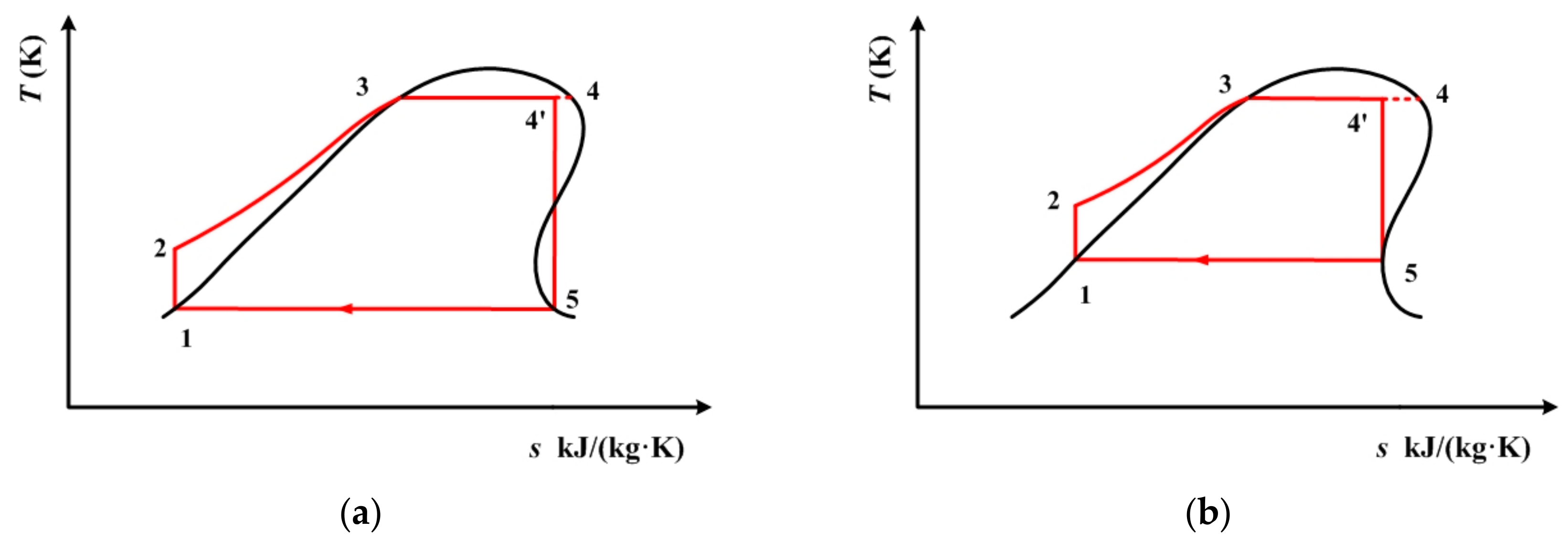
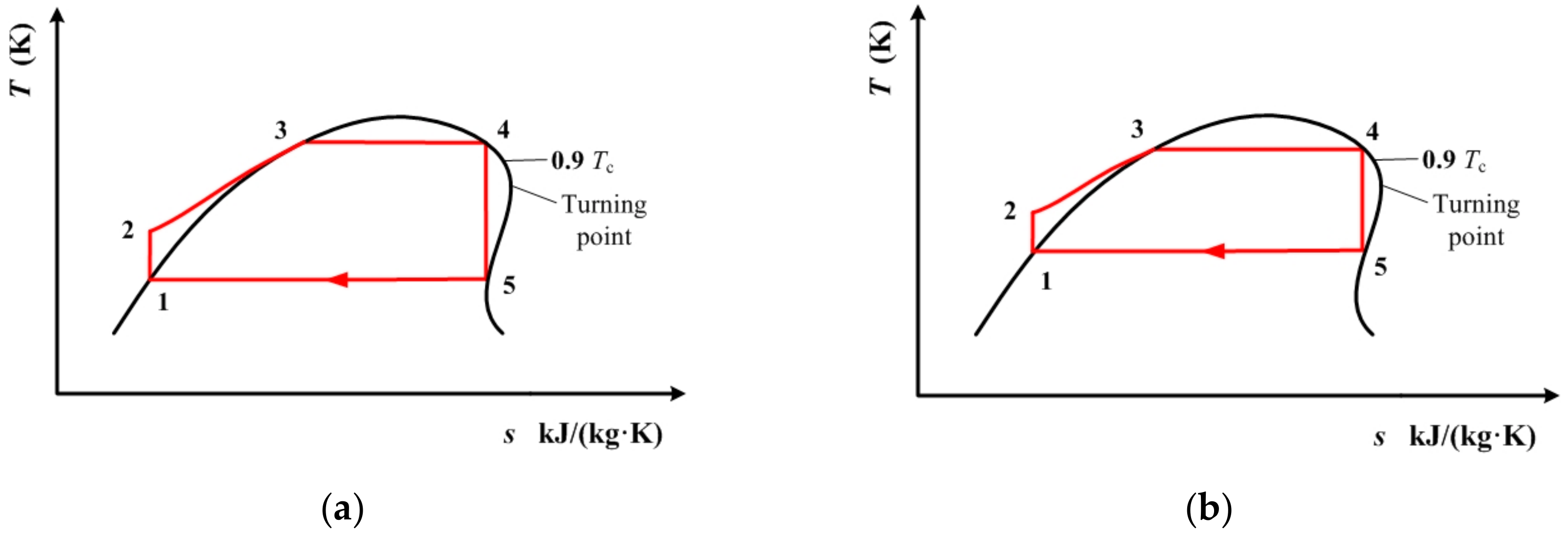
2.2.1. Thermodynamic Setting and Description

The analysis provided in the previous subsection was based on the operating conditions of expander inlet being known, which will act as a determinant on condensation temperature. The results show that the difference in thermodynamic performance between the two working modes is very small. Therefore, in this subsection, we will first attempt to determine and set the condensation temperature, and subsequently conduct the thermodynamic performance analysis.
According to [47], 320 K and 290 K are the recommended condensation temperatures for working fluids with high and low critical temperatures, respectively. These two condensation temperatures can be achieved using air cooling and water cooling. In order to perform a detailed analysis, the thermodynamic performance of the above three working fluids are calculated with condensation temperature varying from 290 K to 320 K. The whole cycle process for cis-butene is depicted in Figure 6. The process for R1234yf and R1234ze(E) are depicted in Figure 7. In Figure 6 and Figure 7, the temperature at point 4(T4) is still set as the extreme temperature of the subcritical ORC, which is 0.9Tc (critical temperature). Line 4’–5 is an isentropic line. Point 5 is on the saturated vapor curve. The temperature at point 5 (T5) is the same as the condensation temperature, which is varied between 290 K and 320 K. From Figure 6 and Figure 7, it can be seen that point 4’ is not in a saturated state, and has a vapor quality.
In Figure 6 and Figure 7, the net work output is calculated by
w net = ( h 4 h 5 ) ( h 2 h 1 ) ,
thermal efficiency is calculated by
η = w net q e = ( h 4 h 5 ) ( h 2 h 1 ) h 4 h 2 ,
the heat exchange load of the condenser is calculated by
q c = h 5 h 1 ,
and the vapor quality of the working fluid is calculated by
x = s 4 s 3 s 4 s 3 ,
It should be noted, here, that for cis-butene, 320 K only corresponds to the local minimum point of entropy on its saturated vapor curve, as shown in Figure 6b. Meanwhile, for R1234yf and R1234ze(E), 290 K, which is their lowest condensation temperature, is higher than the temperature which corresponds to the local minimum entropy.
The subcritical ORC depicted in Figure 4 is still used for the purpose of comparison. The temperature at point 4, which is the same as the temperature of the expander inlet, is still set to be same as the temperature at the turning point. State point 4 is still on the saturated vapor curve. Point 6 is on the saturated vapor curve, and its temperature (T6) is the same as the condensation temperature, which is varied between 290 K and 320 K.

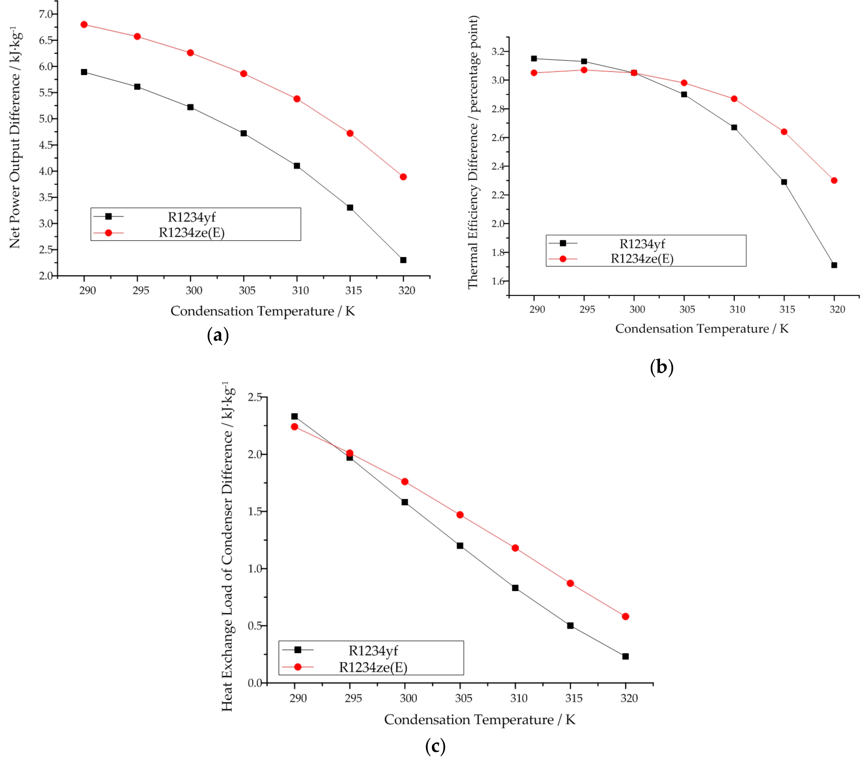
2.2.2. Results and Discussion

Table 3 lists the net power output, thermal efficiency, and heat exchange load of the condenser for cis-butene, R1234yf, and R1234ze(E) when the condensation temperature is known.
Based on the data listed in Table 3, it can be seen that each of these three working fluids exhibits a better thermodynamic performance when adopting the vapor–liquid two-phase expansion mode. However, the difference in thermodynamic performance between the two modes is not very large. Of the three working fluids, cis-butene has the best performance in terms of net power output and thermal efficiency, while R1234yf and R1234ze(E) have a better performance with respect to the heat exchange load of the condenser. The indexes of all three working fluids decrease with increasing condensation temperature under both working modes, the vapor–liquid two-phase expansion mode and the traditional mode.
If we compare the two working modes with respect to the same indicator of the same working fluid, it can be seen that cis-butene behaves differently from the other two working fluids. For cis-butene, the difference between the two modes with respect to net power output decreases first, and then increases with increasing condensation temperature. Meanwhile, for R1234yf and R1234ze(E), the difference increases. This trend can be seen in Figure 8a. For cis-butene, the difference in thermal efficiency remains basically unchanged at first, and then increases with the increase of condensation temperature. Meanwhile, for R1234yf and R1234ze(E), this difference increases. This can be seen in Figure 8b. For cis-butene, the difference in the heat exchange load of the condenser increases with increasing condensation temperature. Meanwhile, for R1234yf and R1234ze(E), this difference decreases. This can be seen in Figure 8c.
Additionally, from Table 3, it can be seen that the vapor quality of cis-butene decreases with increasing condensation temperature. Meanwhile, for R1234yf and R1234ze(E), the vapor quality increases. The vapor quality of all three working fluids is very high. In other words, they are close to a saturated vapor state.
The reason for all of the above differences lies in the different relative positions of the condensation temperature range on the saturated vapor curves of the different working fluids. Specifically, for cis-butene, 320 K corresponds to the local minimum entropy. This factor is well illustrated and explained in Figure 6 and Figure 7.
In summary, cis-butene can be selected as a suitable working fluid in the subcrictical cycle model when the condensation temperature is known. It is suitable for both open and closed types of heat source, with a higher cost to the heat exchanger.

3. Ideal Transcritical Cycle Model

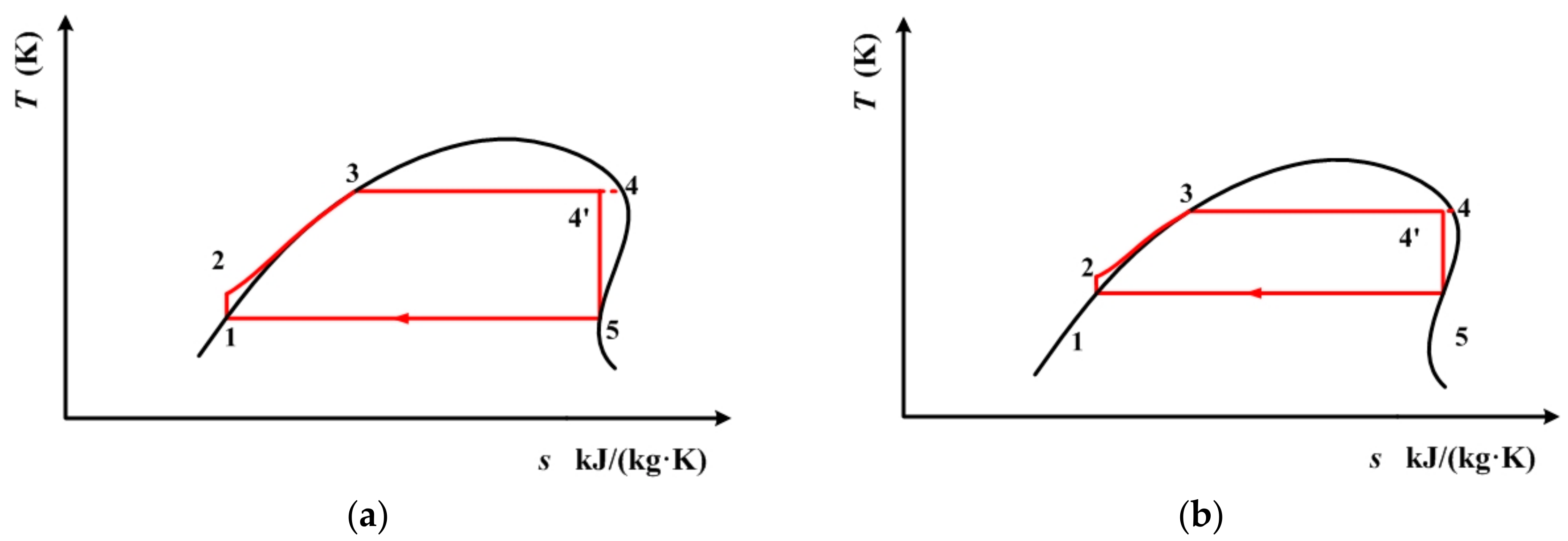
3.1. Thermodynamic Setting and Description

Based on the calculation and analysis of the subcritical cycle model when the working conditions of the expander inlet or the condensation temperature are known, it can be seen that the differences in thermodynamic performance between the vapor–liquid two-phase expansion mode and the traditional mode are not large. In other words, the advantage represented by the tolerance of the single-screw expander for two-phase fluids has not been fully utilized under subcritical conditions. Therefore, in this section, the transcritical cycle model is established to analyze the performance of the single-screw expander.
Similar to the settings in the previous subsection, condensation temperature is used to determine the maximum temperature in the transcritical cycle model. Figure 9 depicts the whole cycle process for cis-butene. Figure 10 depicts the cycle for R1234yf and R1234ze(E). In these two figures, both point 4 and point 5 are on the saturated vapor curve. Line 4–5 is an isentropic line. The temperature at point 4 is higher than 0.9Tc (critical temperature), which is the extreme temperature of the subcritical region. As mentioned before, for cis-butene, 320 K only corresponds to the local minimum point of entropy on its saturated vapor curve, as shown in Figure 9b. Meanwhile, for R1234yf and R1234ze(E), 290 K, which is their lowest condensation temperature, is higher than the temperature corresponding to their local minimum entropy.
Due to the different relative positions of the condensation temperature range on the saturated vapor curves, the maximum cycle temperature that corresponds to the condensation temperature is different for the three working fluids. For cis-butene, the maximum cycle temperature that corresponds to the lowest condensation temperature is lower than the maximum cycle temperature that corresponds to the highest condensation temperature. Meanwhile, for R1234yf and R1234ze(E), their maximum cycle temperature that corresponds to the lowest condensation temperature is higher than the maximum cycle temperature that corresponds to the highest condensation temperature. Figure 9 and Figure 10 illustrate this difference. The equations for calculating the three indicators in Figure 9 and Figure 10 are the same as the equations used for the calculations for Figure 3.
The cycle depicted in Figure 4 is still used for the purpose of comparison. The temperature at point 4, which is the same as the temperature at the expander inlet, is still set to be the same as the temperature at the turning point. State point 4 is still on the saturated vapor curve. Point 6 is on the saturated vapor curve, and its temperature (T6) is the same as the condensation temperature, which is varied between 290 K and 320 K.

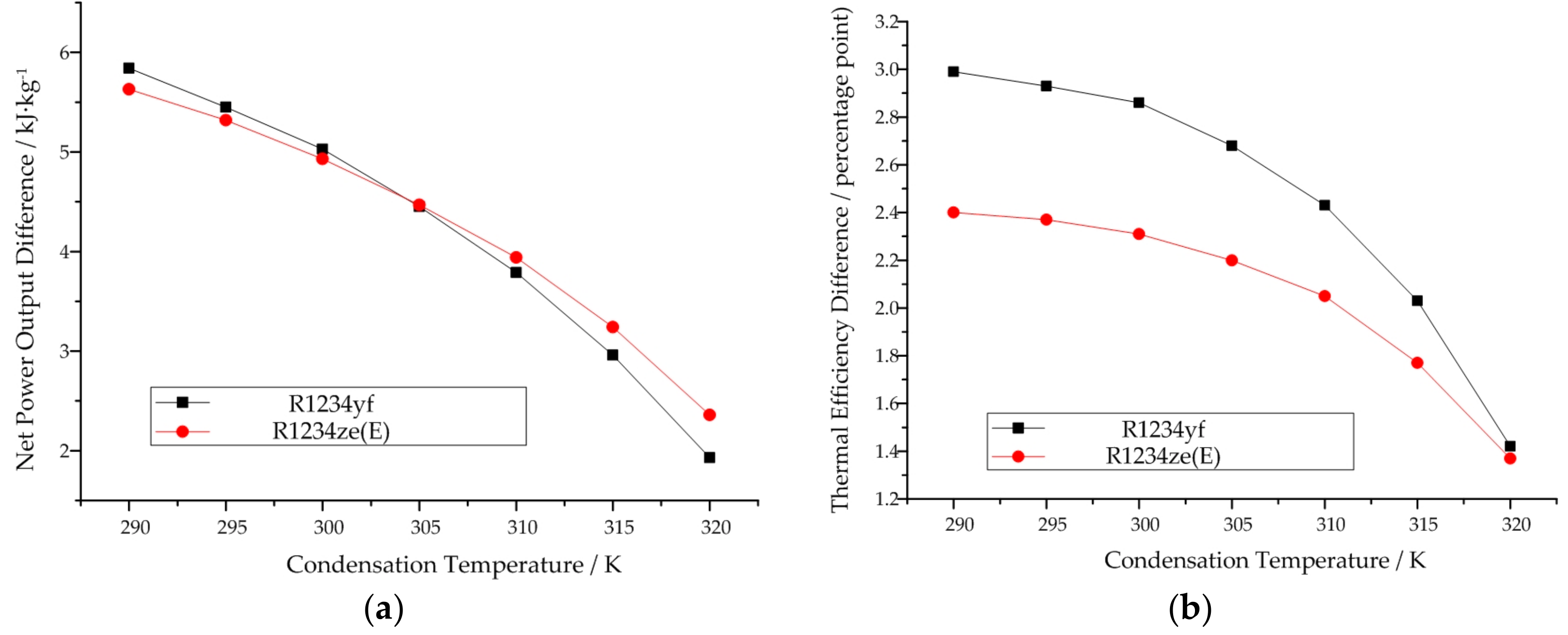
3.2. Results and Discussion

Table 4 lists the net power output, thermal efficiency, and heat exchange load of the condenser for cis-butene, R1234yf, and R1234ze(E) in transcritical ORC when the condensation temperature is known.
Based on the data listed in Table 4, it can be seen that when the condensation temperature is varied from 290 K to 320 K, the expander inlet temperature of cis-butene exceeds 130 °C (400 K). It has been mentioned that the maximum working temperature of the single-screw expander is 130 °C (400 K). Although it can work at temperatures higher than 400 K for a short time, its working life will be greatly reduced. Therefore, it is not recommended that single-screw expanders be operated at temperatures higher than 400 K. When 400 K is set as the inlet temperature of the single-screw expander, the corresponding condensation temperature will be 284.7 K. At this condensation temperature, the vapor–liquid two-phase expansion mode exhibits a better performance than the traditional mode.
The same as for the subcritical cycle model when the condensation temperature is known, all three thermodynamic indexes decrease with increasing condensation temperature under both working modes, the vapor–liquid two-phase expansion mode and the traditional mode. This trend can be seen in Figure 11. When comparing R1234yf with R1234ze(E) at the same condensation temperature, R1234ze(E) has better thermodynamic performance than R1234yf in terms of net power output and thermal efficiency. However, the heat exchange load of the condenser for R1234ze(E) is a little bit higher than that of R1234yf. The difference in thermodynamic performance for both R1234yf and R1234ze(E) between the two working modes decreases with increasing condensation temperature.
In summary, in comparison with cis-butene, R1234yf and R1234ze(E) are more suitable for working in the transcritical cycle. Moreover, R1234ze(E) can be selected as a suitable working fluid in the transcritical cycle model when the condensation temperature is known. It is suitable for both open and closed types of heat source, with a slightly higher cost in the heat exchanger.

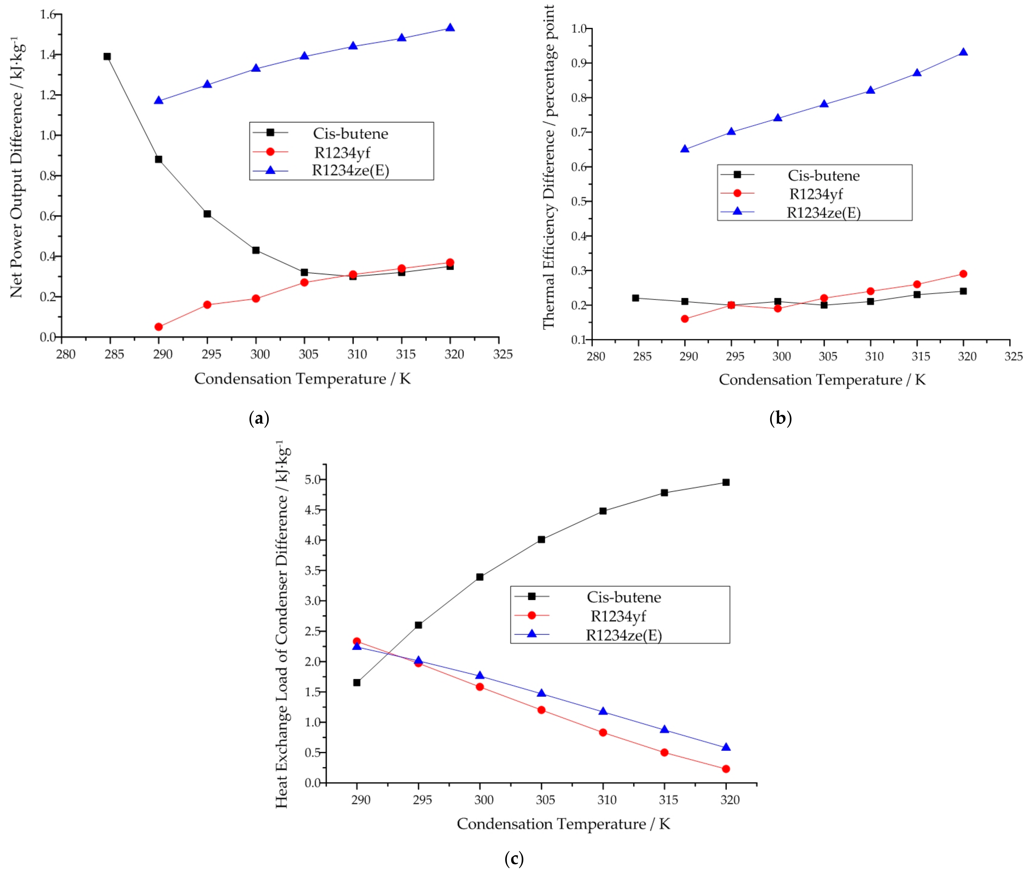
3.3. Comparisons of Subcritical and Transcritical Cycle Models

If we compare the thermodynamic performance of the same working fluid (R1234yf or R1234ze(E)) when working in the subcritical and transcritical cycle models at the same condensation temperature, it can be obviously found that the thermodynamic performance in the transcritical cycle model is better than that in the subcritical cycle. For both R1234yf and R1234ze(E), the difference in their thermodynamic performances between the subcritical and transcritical cycle models decreases with increasing condensation temperature. Figure 12 depicts this trend. As for cis-butene, its maximum working temperature is 400 K, which corresponds to a condensation temperature of 284.7 K. At this temperature, the thermodynamic performance of cis-butene in the transcritical cycle model is better than that in the subscritical cycle model.

4. Analysis of the Subcritical and Transcritical Cycles Considering the Isentropic Efficiency of the Expander

4.1. Thermodynamic Setting and Description

The above two sections analyzed the ideal subcritical and ideal transcritical cycle models. They are based on the isentropic efficiency of the single-screw expander being 100%. However, in practical applications, the isentropic efficiency of different expanders needs to be taken into account. Therefore, in this section, the subcritical and transcritical cycles are analyzed considering the isentropic efficiency of the expanders. Figure 13 depicts the subcritical and transcritical cycles of cis-butene when considering the isentropic efficiency of the expander. Figure 14 depicts the subcritical and transcritical cycles of R1234yf and R1234ze(E) when considering the isentropic efficiency of the expander. In these figures, the blue dotted lines represent the expansion processes when considering the isentropic efficiency of the expander.
In Figure 13 and Figure 14, isentropic efficiency is calculated by
η e x = h 4 h 5 h 4 h 5 ,
First of all, the isentropic efficiencies of different types of expander need to be determined. Nowadays, screw expanders show a much greater technical maturity than scroll and piston expanders [13]. The internal efficiency of single-screw expanders has exceeded 50%, and the maximum is about 65% [21,48]. Therefore, 65% is used for the analysis of single-screw expanders in this section. Table 5 lists the range of net work output values for different working fluids when taking the 65% isentropic efficiency of the single-screw expander into account. Based on the net work output range listed in Table 5, the type of expander used to perform the the comparison with single-screw expander can be determined. According to [9], piston expanders are suitable for cis-butene(cis-2-butene) and can be used for the purpose of comparison with single-screw expander. Meanwhile, scroll expanders are suitable for R1234yf and R1234ze(E). In the work conducted by Sapin et al., the efficiency of the reciprocating-piston expander ranges from 48% to 68% [49]. Therefore, 62% is adopted as the isentropic efficiency for the piston expander [50]. For scroll expanders, the maximum isentropic efficiency has reached up to 80% [51]. In this sections, we have adopted 68% as its isentropic efficiency when used in ORC [52].

4.2. Results and Discussion

Table 6, Table 7 and Table 8 show the comparisons of the thermodynamic performance of the three working fluids with and without consideration of the isentropic efficiency of the expander.
From Table 6, it can be seen that when considering the isentropic efficiency of the expander at condensation temperatures of 290 K and 295 K, the heat exchange load of the condenser in the traditional cycle, in which the piston expander is used, is smaller than that in the transcritical cycle in which the single-screw expander is used, but bigger than that in subcritical cycle in which the single-screw expander is used. However, at the same condensation temperature, the other aspects of thermodynamic performance of the single-screw expander working in subcritical or transcritical cycles were better than those of the piston expander working in the traditional cycle. Beyond that, at all other condensation temperatures, all aspects of the thermodynamic performance of the single-screw expander working in subcritical or transcritical cycles were better than those of the piston expander working in the traditional cycle.
From Table 7, it can be seen that when considering the isentropic efficiency of the expander, the net power output and the thermal efficiency of the single-screw expander working in the subcritical cycle are lower than those of the scroll expander working in the traditional cycle at condensation temperatures of 290 K, 295 K, 300 K, 305 K, and 310 K. At the same time, the heat exchange load of the condenser of the single-screw expander is also lower than that of the scroll expander. However, at condensation temperatures of 315 K and 320 K, the net power output and thermal efficiency of the single-screw expander working in the subcritical cycle are higher than those of the scroll expander working in the traditional cycle. Among the three working conditions, the single-screw expander working in the transcritical cycle has the highest net power output and thermal efficiency.
From Table 8, it can be seen that when considering the isentropic efficiency of the expander, the net power output and thermal efficiency of the single-screw expander working in both the subcritical and transcritical cycles are higher than those of the scroll expander working in the traditional cycle. The thermodynamic performance of the single-screw expander working in the transcritical cycle is better than that of the single-screw expander working in the subcritical cycle. At the same time, the heat exchange load of the condenser is also a little bit higher.
From above three tables, it can be seen that if the isentropic efficiency of the expander is considered, then among the subcritical cycle with the single-screw expander, the transcritical cycle with the single-screw expander, and the traditional cycle with the piston/scroll expander, the transcritical cycle has the highest net power output and thermal efficiency. At the same time, it has a slightly higher heat exchange load of the condenser. When comparing the subcritical cycle and the traditional cycle, as for cis-butene, all aspects of the thermodynamic performance of the single-screw expander are better at all condensation temperatures. For R1234yf, all aspects of the thermodynamic performance of the single-screw expander are better at a condensation temperature of 315 K. For R1234ze(E), all aspects of the thermodynamic performance of the single-screw expander are better at condensation temperatures ranging from 290 K to 310 K.
Among the three working fluids, cis-butene has the highest net power output and the highest thermal efficiency when working in the subcritical cycle. Meanwhile, R1234ze(E) may be the best choice when working in the transcritical cycle.

5. Conclusions

The organic Rankine cycle (ORC) is a popular technology used in waste heat recovery and medium- to low-temperature heat utilization. The working fluid plays a very important role in the thermodynamic cycle. The expander is a key device in ORC. In order to give full play to vapor–liquid two-phase expansion tolerance, which is an important characteristic of single-screw expanders, two ORC models—an ideal subcritical cycle model and an ideal transcritical cycle model—were established. On this basis, the isentropic efficiency of the expander was also considered for the purposes of analyzing thermodynamic performance.
Three indicators—namely, net work output, which was used to evaluate open heat source, thermal efficiency, which was used for closed heat source, and the heat exchange load of the condenser, which was used to evaluate economic performance—were chosen to analyze the performance of the ORC systems.
On the basis of our calculations and analyses, it can be seen that, without considering the isentropic efficiency of the expander, ORC systems that use single-screw expanders and undergo a vapor–liquid two-phase expansion are able to obtain higher thermal efficiency, greater net work output, and smaller heat exchange loads of the condenser. Cis-butene may be the best candidate when working in the subcritical cycle. HFO working fluids are more suitable for working in the transcritical cycle, and HFO-1234ze(E) may be the best.
When considering the isentropic efficiency of the expander, cis-butene is still the best choice for working in the subcritical cycle. Meanwhile, for the transcritical cycle, HFO-1234ze(E) may still be the best.

Author Contributions

Conceptualization, X.Z.; Data curation, Y.Z., X.Z., and M.C.; Formal analysis, X.Z. and Y.Z.; Funding acquisition, X.Z.; Methodology, X.Z.; Resources, Y.W., C.M., and J.W.; Writing—Original Draft, X.Z.; Writing—Review & Editing, J.W.

Funding

This research was funded by the National Natural Science Foundation of China (Grant No.51506001) and the Beijing Municipal Education Commission (KM201710005029). The authors gratefully acknowledge them for financial support of this work.

Conflicts of Interest

The authors declare no conflict of interest.

References

  1. Imre, A.; Kustán, R.; Groniewsky, A. Thermodynamic selection of the optimal working fluid for organic Rankine cycles. Energies 2019, 12, 2028. [Google Scholar] [CrossRef]
  2. Zhang, X.; He, M.; Wang, J. A new method used to evaluate organic working fluids. Energy 2014, 67, 363–369. [Google Scholar] [CrossRef]
  3. Liu, B.; Chien, K.; Wang, C. Effect of working fluids on organic Rankine cycle for waste heat recovery. Energy 2004, 29, 1207–1217. [Google Scholar] [CrossRef]
  4. Longo, G.; Mancin, S.; Righetti, G.; Zilio, C. Saturated vapour condensation of R134a inside a 4 mm ID horizontal smooth tube: Comparison with the low GWP substitutes R152a, R1234yf and R1234ze(E). Int. J. Heat Mass Transf. 2019, 133, 461–473. [Google Scholar] [CrossRef]
  5. Ghafri, S.; Rowland, D.; Akhfash, M.; Arami-Niya, A.; Khamphasith, M.; Xiong, X.; Tsuji, T.; Tanaka, Y.; Seiki, Y.; May, E.; et al. Thermodynamic properties of hydrofluoroolefin (R1234yf and R1234ze(E)) refrigerant mixtures: Density, vapour-liquid equilibrium, and heat capacity data and modeling. Int. J. Refrig. 2019, 98, 249–260. [Google Scholar] [CrossRef]
  6. Yang, J.; Ye, Z.; Yu, B.; Ouyang, H.; Chen, J. Simultaneous experimental comparison of low-GWP refrigerants as drop-in replacements to R245fa for Organic Rankine cycle application: R1234ze(Z), R1233zd(E), and R1336mzz(E). Energy 2019, 173, 721–731. [Google Scholar] [CrossRef]
  7. Li, Z.; Liang, K.; Jiang, H. Experimental study of R1234yf as a drop-in replacement for R134a in an oil-free refrigeration system. Appl. Therm. Eng. 2019, 153, 646–654. [Google Scholar] [CrossRef]
  8. Zhang, X.; Cao, M.; Yang, X.; Guo, H.; Wang, J. Economic analysis of organic Rankine cycle using R123 and R245fa as working fluids and a demonstration project report. Appl. Sci. 2019, 9, 288. [Google Scholar] [CrossRef]
  9. Bao, J.; Zhao, L. A review of working fluid and expander selections for organic Rankine cycle. Renew. Sustain. Energy Rev. 2013, 24, 325–342. [Google Scholar] [CrossRef]
  10. Velez, F.; Segovia, J.J.; Martín, M.C.; Antolín, G.; Chejne, F.; Quijano, A. A technical, economical and market review of organic Rankine cycles for the conversion of low-grade heat for power generation. Renew. Sustain. Energy Rev. 2012, 16, 4175–4189. [Google Scholar] [CrossRef]
  11. Lei, B.; Wang, W.; Wu, Y.; Ma, C.; Wang, J.; Zhang, L.; Li, C.; Zhao, Y.; Zhi, R. Development and experimental study on a single screw expander integrated into an Organic Rankine Cycle. Energy 2016, 116, 43–52. [Google Scholar] [CrossRef]
  12. Dumont, O.; Parthoens, A.; Dickes, R.; Lemort, V. Experimental investigation and optimal performance assessment of four volumetric expanders (scroll, screw, piston and roots) tested in a small-scale organic Rankine cycle system. Energy 2018, 165, 1119–1127. [Google Scholar] [CrossRef] [Green Version]
  13. Lemort, V.; Guillaume, L.; Legros, A.; Declayea, S.; Quoilin, S. A comparison of piston, screw and scroll expanders for small scale Rankine cycle systems. In Proceedings of the 3rd International Conference on Microgeneration and Related Technologies, Naples, Italy, 15–17 April 2013. [Google Scholar]
  14. Goodyear, J.W. Pressure Energy Translating and Like Devices. US Patent No.2716861, 6 September 1955. [Google Scholar]
  15. Zimmern, B. Worm Rotary Compressors with Liquid Joints. US Patent No.3180565, 27 April 1965. [Google Scholar]
  16. Desideri, A.; Broek, M.; Gusev, S.; Lemort, V.; Quoilin, S. Experimental campaign and modeling of a low-capacity waste heat recovery system based on a single screw expander. In Proceedings of the 22nd International Compressor Engineering Conference at Purdue, West Lafayette, IN, USA, 14–17 July 2014. [Google Scholar]
  17. Ziviani, D.; Groll, E.A.; Braun, J.E.; Paepe, M. Review and update on the geometry modeling of single-screw machines with emphasis on expanders. Int. J. Refrig. 2018, 92, 10–26. [Google Scholar] [CrossRef]
  18. Giuffrida, A. Improving the semi-empirical modelling of a single-screw expander for small organic Rankine cycles. Appl. Energy 2017, 193, 356–368. [Google Scholar] [CrossRef]
  19. Shen, L.; Wang, W.; Wu, Y.; Cheng, L.; Lei, B.; Zhi, R.; Ma, C. Theoretical and experimental analyses of the internal leakage in single-screw expanders. Int. J. Refrig. 2018, 86, 273–281. [Google Scholar] [CrossRef]
  20. Shen, L.; Wang, W.; Wu, Y.; Lei, B.; Zhi, R.; Lu, Y.; Wang, J.; Ma, C. A study of clearance height on the performance of single-screw expanders in small-scale organic Rankine cycles. Energy 2018, 153, 45–55. [Google Scholar] [CrossRef]
  21. Lu, Y.; He, W.; Wu, Y.; Ji, W.; Ma, C.; Guo, H. Performance study on compressed air refrigeration system based on single screw expander. Energy 2013, 55, 762–768. [Google Scholar] [CrossRef]
  22. He, W.; Wu, Y.; Peng, Y.; Zhang, Y.; Ma, C.; Ma, G. Influence of intake pressure on the performance of single screw expander working with compressed air. Appl. Therm. Eng. 2013, 51, 662–669. [Google Scholar] [CrossRef]
  23. Zhang, Y.; Wu, Y.; Xia, G.; Ma, C.; Ji, W.; Liu, S.; Yang, K.; Yang, F. Development and experimental study on organic Rankine cycle system with single-screw expander for waste heat recovery from exhaust of diesel engine. Energy 2014, 77, 499–508. [Google Scholar] [CrossRef]
  24. Yang, K.; Zhang, H.; Song, S.; Zhang, J.; Wu, Y.; Zhang, Y.; Wang, H.; Chang, Y.; Bei, C. Performance Analysis of the Vehicle Diesel Engine-ORC Combined System Based on a Screw Expander. Energies 2014, 7, 3400–3419. [Google Scholar] [CrossRef] [Green Version]
  25. Wajs, J.; Mikielewicz, D.; Bajor, M.; Kneba, Z. Experimental investigation of domestic micro-CHP based on the gas boiler fitted with ORC module. Arch. Thermodyn. 2016, 37, 79–93. [Google Scholar] [CrossRef]
  26. Mikielewicz, D.; Mikielewicz, J. A thermodynamic criterion for selection of working fluid for subcritical and supercritical domestic micro CHP. Appl. Therm. Eng. 2010, 30, 2357–2362. [Google Scholar] [CrossRef] [Green Version]
  27. Mikielewicz, D.; Wajs, J.; Mikielewicz, J. Alternative cogeneration thermodynamic cycles for domestic ORC. Chem. Process. Eng. 2018, 39, 75–84. [Google Scholar]
  28. Desideri, A.; Gusev, S.; Broek, M.; Lemort, V.; Quoilin, S. Experimental comparison of organic fluids for low temperature ORC (organic Rankine cycle) systems for waste heat recovery applications. Energy 2016, 97, 460–469. [Google Scholar]
  29. White, M.T.; Oyewunmi, O.A.; Chatzopoulou, M.A.; Pantaleo, A.M.; Haslam, A.J.; Markides, C.N. Computer-aided working-fluid design, thermodynamic optimisation and thermoeconomic assessment of ORC systems for waste-heat recovery. Energy 2018, 161, 1181–1198. [Google Scholar] [CrossRef]
  30. Zhang, X.; Zhang, C.; He, M.; Wang, J. Selection and Evaluation of Dry and Isentropic Organic Working Fluids Used in Organic Rankine Cycle Based on the Turning Point on Their Saturated Vapor Curves. J. Therm. Sci. 2019. [Google Scholar] [CrossRef]
  31. Györke, G.; Deiters, U.K.; Groniewsky, A.; Lassu, I.; Imre, A.R. Novel Classification of Pure Working Fluids for Organic Rankine Cycle. Energy 2018, 145, 288–300. [Google Scholar] [CrossRef]
  32. Quoilin, S.; Broek, M.V.D.; Declaye, S.; Dewallef, P.; Lemort, V. Techno-economic survey of Organic Rankine Cycle (ORC) systems. Renew. Sustain. Energy Rev. 2013, 22, 168–186. [Google Scholar] [CrossRef] [Green Version]
  33. Lemmon, E.W.; Huber, M.L.; McLinden, M.O. NIST Standard Reference Database 23: Reference Fluid Thermodynamic and Transport Properties-REFPROP; Version 9.1; National Institute of Standard Technology: Boulder, CO, USA, 19 February 2017. [Google Scholar]
  34. Cis-2-butene. Available online: https://www.chemicalbook.com/ChemicalProductProperty_EN_CB7388192.htm (accessed on 1 July 2019).
  35. Zhai, H.; Shi, L.; An, Q. Influence of working fluid properties on system performance and screen evaluation indicators for geothermal ORC (organic Rankine cycle) system. Energy 2014, 74, 2–11. [Google Scholar] [CrossRef]
  36. American Society of Heating, Refrigerating and Air-Conditioning Engineers, Inc. ANSI/ASHRAE Standard 34-2007. Designation and Safety Classification of Refrigerants. ISSN: 1041-2336. Available online: https://www.ashrae.org/File%20Library/Technical%20Resources/Standards%20and%20Guidelines/Standards%20Addenda/34_2007_ak_FINAL.pdf (accessed on 1 July 2019).
  37. Intergovernmental Panel on Climate Change. Changes in atmospheric constituents and in radiative forcing. In Climate Change 2007—The Physical Science Basis, Contribution of Working Group I to the Fourth Assessment Report of the IPCC; Cambridge University Press: Cambridge, UK, 2007; p. 212. [Google Scholar]
  38. R116 Refrigerant (Hexafluoroethane, C2F6). Available online: http://www.china-refrigerants.com/r116.htm (accessed on 1 July 2019). (In Chinese).
  39. American Society of Heating, Refrigerating and Air-Conditioning Engineers, Inc. ANSI/ASHRAE Standard 34-2013. Designation and Safety Classification of Refrigerants. ISSN: 1041-2336. Available online: https://www.ashrae.org/technical-resources/standards-and-guidelines/standards-addenda/ansi-ashrae-standard-34-2013-designation-and-safety-classification-of-refrigerants (accessed on 1 July 2019).
  40. American Society of Heating, Refrigerating and Air-Conditioning Engineers, Inc. ANSI/ASHRAE Addenda 2015 Supplement. Designation and safety classification of refrigerants. ISSN: 1041-2336. Available online: https://www.ashrae.org/File%20Library/Technical%20Resources/Standards%20and%20Guidelines/Standards%20Addenda/34_2013_2015Supplement_20150210.pdf (accessed on 1 July 2019).
  41. Climate-Friendly Alternatives to HFCs. Available online: https://ec.europa.eu/clima/policies/f-gas/alternatives_en (accessed on 1 July 2019).
  42. Sánchez, D.; Cabello, R.; Llopis, R.; Arauzo, I.; Catalán-Gil, J.; Torrella, E. Energy performance evaluation of R1234yf, R1234ze(E), R600a, R290 and R152a as low-GWP R134a alternatives. Int. J. Refrig. 2017, 74, 269–282. [Google Scholar] [CrossRef]
  43. Ayachi, F.; Ksayer, E.B.; Zoughaib, A.; Neveu, P. ORC optimization for medium grade heat recovery. Energy 2014, 68, 47–56. [Google Scholar] [CrossRef]
  44. Le, V.L.; Feidt, M.; Kheiri, A.; Pelloux-Prayer, S. Performance optimization of low-temperature power generation by supercritical ORCs (organic Rankine cycles) using low GWP (global warming potential) working fluids. Energy 2014, 67, 513–526. [Google Scholar] [CrossRef]
  45. Yan, J.L. Thermodynamic principles and formulas for choosing working fluids and parameters in designing power plant of low temperature heat. J. Eng. Thermophys. 1982, 3, 7. (In Chinese) [Google Scholar]
  46. He, C.; Liu, C.; Zhou, M. A new selection principle of working fluids for subcritical organic Rankine cycle coupling with different heat sources. Energy 2014, 68, 283–291. [Google Scholar] [CrossRef]
  47. Chen, H.; Goswami, D.Y.; Stefanakos, E.K. A review of thermodynamic cycles and working fluids for the conversion of low-grade heat. Renew. Sustain. Energy Rev. 2010, 14, 3059–3067. [Google Scholar] [CrossRef]
  48. Ziviani, D.; Gusev, S.; Lecompte, S.; Groll, E.A.; Braun, J.E.; Horton, W.T.; Broek, M.; De Paepe, M. Characterizing the performance of a single-screw expander in a small-scale organic Rankine cycle for waste heat recovery. Appl. Energy 2016, 181, 155–170. [Google Scholar] [CrossRef]
  49. Sapin, P.; Simpson, M.; White, A.J.; Markides, C. Lumped dynamic analysis and design of a high-performance reciprocating-piston expander. In Proceedings of the 30th International Conference on Efficiency, Cost, Optimisation, Simulation and Environmental Impact of Energy Systems, San Diego, CA, USA, 2–6 July 2017. [Google Scholar]
  50. Zhang, B.; Peng, X.; He, Z.; Xing, Z.; Shu, P. Development of a double acting free piston expander for power recovery in transcritical CO2 cycle. Appl. Therm. Eng. 2007, 27, 1629–1636. [Google Scholar] [CrossRef]
  51. Song, P.; Wei, M.; Shi, L.; Danish, S.N.; Ma, C. A review of scroll expanders for organic Rankine cycle systems. Appl. Therm. Eng. 2015, 75, 54–64. [Google Scholar] [CrossRef]
  52. Lemort, V.; Quoilin, S.; Cuevas, C.; Lebrun, J. Testing and modeling a scroll expander integrated into an Organic Rankine Cycle. Appl. Therm. Eng. 2009, 29, 3094–3102. [Google Scholar] [CrossRef] [Green Version]
Figure 1. Configuration of a single-screw expander.
Energies 12 03197 g001
Figure 2. Working processes of single-screw expanders: (a) suction, (b) expansion, and (c) discharge.
Energies 12 03197 g002
Figure 3. Subcritical ORC with a single-screw expander when the working conditions of the expander inlet are known.
Energies 12 03197 g003
Figure 4. Traditional subcritical ORC with dry/isentropic working fluid.
Energies 12 03197 g004
Figure 5. Shape of the saturated vapor curve of R1234yf, resulting in two intersections with the isentropic line.
Energies 12 03197 g005
Figure 6. Subcritical ORC for cis-butene with a single-screw expander when the condensation temperature is known: (a) 290 K, (b) 320 K.
Energies 12 03197 g006
Figure 7. Subcritical ORC for R1234yf and R1234ze(E) with a single-screw expander when the condensation temperature is known: (a) 290 K, (b) 320 K.
Energies 12 03197 g007
Figure 8. Variation in the difference in thermodynamic performance with increasing condensation temperature in the subcritical cycle model when the condensation temperature is known: (a) net power output, (b) thermal efficiency, (c) heat exchange load of the condenser.
Energies 12 03197 g008
Figure 9. Transcritical ORC for cis-butene with single-screw expander when the condensation temperature is known: (a) 290 K, (b) 320 K.
Energies 12 03197 g009
Figure 10. Transcritical ORC for R1234yf and R1234ze(E) with single-screw expander when the condensation temperature is known: (a) 290 K, (b) 320 K.
Energies 12 03197 g010
Figure 11. Variation in the difference in thermodynamic performance with increasing condensation temperature in the transcritical cycle model when the condensation temperature is known: (a) net power output, (b) thermal efficiency, (c) heat exchange load of the condenser.
Energies 12 03197 g011
Figure 12. Thermodynamic performance difference variation between subcritical and transcritical cycle with increase of condensation temperature: (a) Net power output, (b)Thermal efficiency.
Energies 12 03197 g012
Figure 13. (a) Subcritical and (b) transcritical cycles of cis-butene when considering the isentropic efficiency of the expander.
Energies 12 03197 g013
Figure 14. (a) Subcritical and (b) transcritical cycles of R1234yf and R1234ze(E) when considering the isentropic efficiency of the expander.
Energies 12 03197 g014
Table 1. Main thermodynamic, safety, and environmental properties of 6 working fluids.
Working FluidCritical Temperature (Tc)/KThe extreme Temperature of Subcritical Region (0.9TC)/KTurning Point Temperature/KSafety GroupGlobal Warming Potential (GWP), 100 year
cis-butene(cis-2-butene)435.75392.18390N/A~20 [35]
R11471.11424.00395A1 [36]4750 [37]
R116293.03263.73255A1 [36]5700 [38]
R1234yf367.85331.07330A2L 1 [39,40,41]<1 [42]/4 [43]
R1234ze(E)382.51344.26340A2L 2 [39,40,41]<1 [42]/6 [44]
R142b410.26369.24350A2 [36]2310 [37]
1,2 A2L is a lower flammability refrigerant with a maximum burning velocity of ≤10 cm/s.
Table 2. Thermodynamic performance of the remaining three working fluids in the subcritical cycle model when the working conditions at the expander inlet are known.
Working FluidWorking ModeExpander Inlet Temperature T4/KExpander Outlet Temperature T5/KNet Power Output/kJ∙kg−1Thermal Efficiency/%Heat Exchange Load of Condenser/kJ∙kg−1
cis-butene (cis-2-butene)Vapor–liquid two-phase expansion mode392.18283.1113.8821.82408.06
Traditional mode390283.12112.4021.59408.10
R1234yfVapor–liquid two-phase expansion mode331.07223.5 1N/AN/AN/A
Traditional mode330223.51 2N/AN/AN/A
R1234ze(E)Vapor–liquid two-phase expansion mode344.26331(237.8 3)5.113.58137.78
Traditional mode340331.083.562.52137.87
1,2,3 The temperature is too low and beyond the usual condensation temperature range.
Table 3. Thermodynamic performance of the three working fluids in the subcritical cycle model when the condensation temperature is known.
Working FluidWorking ModeCondensation Temperature T5/KCondensation Temperature T6/KNet Power Output/kJ∙kg−1Thermal Efficiency/%Heat Exchange Load of Condenser/kJ∙kg−1Vapor Quality
cis-butene (cis-2-butene)Vapor–liquid two-phase expansion mode284.7/111.4221.51406.460.9978
290103.4820.51401.090.9913
29596.3319.57395.910.9864
30089.4618.64390.600.9825
30582.8517.70385.170.9797
31076.5116.77379.590.9777
31570.4015.85373.870.9766
32064.4814.91367.980.9762
Traditional mode/284.7110.0321.29406.90/
290102.6020.30402.74
29595.7219.37398.51
30089.0318.43393.99
30582.5317.50389.18
31076.2116.56384.07
31570.0815.62378.65
32064.1314.67372.93
R1234yfVapor–liquid two-phase expansion mode290/17.6710.43151.670.9766
29515.189.31147.860.9807
30012.718.12143.870.9845
30510.426.94139.650.9886
3108.185.70135.210.9921
3156.064.44130.490.9953
3204.073.14125.470.9980
Traditional mode/29017.6210.27154.00/
29515.029.11149.83
30012.527.93145.45
30510.156.72140.85
3107.875.46136.04
3155.724.18130.99
3203.702.85125.70
R1234ze(E)Vapor–liquid two-phase expansion mode290/25.7012.94172.890.9792
29522.8211.88169.280.9817
30020.0410.80165.510.9845
30517.379.71161.590.9873
31014.798.58157.490.9902
31512.347.46153.180.9930
3209.986.29148.660.9958
Traditional mode/29024.5312.29175.13/
29521.5711.18171.29
30018.7110.06167.27
30515.988.93163.06
31013.357.76158.66
31510.866.59154.05
3208.455.36149.24
Table 4. Thermodynamic performance of the three working fluids in the transcritical cycle model when the condensation temperature is known.
Working FluidWorking ModeCondensation Temperature T5/KCondensation Temperature T6/KExpander Inlet Temperature T4/KNet Power Output/kJ∙kg-1Thermal Efficiency/%Heat Exchange Load of Condenser/kJ∙kg-1
cis-butene (cis-2-butene)Vapor–liquid two-phase expansion mode284.7/400.00116.3722.26406.46
290407.78112.8621.96401.09
295411.20107.4921.35395.91
300413.36101.6720.65390.60
305414.7295.6919.90385.17
310415.6089.7119.11379.60
315416.0583.7918.31373.87
320416.2577.9517.48367.98
Traditional mode/284.7390110.0321.29406.90
290102.6020.30402.74
29595.7219.37398.51
30089.0318.43393.99
30582.5317.50389.18
31076.2116.56384.07
31570.0815.62378.65
32064.1314.67372.93
R1234yfVapor–liquid two-phase expansion mode290/350.7823.5113.42151.67
295349.2520.6312.24147.86
300347.5917.7410.98143.87
305345.4314.879.62139.65
310343.1011.978.13135.21
315340.279.026.47130.49
320336.946.004.56125.47
Traditional mode/29033017.6210.27154.00
29515.029.11149.83
30012.527.93145.45
30510.156.72140.85
3107.875.46136.04
3155.724.18130.99
3203.702.85125.70
R1234ze(E)Vapor–liquid two-phase expansion mode290/361.9931.3315.34172.89
295360.8728.1414.25169.28
300359.4824.9713.11165.51
305357.9121.8411.91161.59
310356.0918.7310.63157.48
315353.9015.589.23153.18
320351.1312.347.66148.66
Traditional mode/29034024.5312.29175.13
29521.5711.18171.29
30018.7110.06167.27
30515.988.93163.06
31013.357.76158.66
31510.866.59154.05
3208.455.36149.24
Table 5. Range of net work output of different working fluids when taking the 65% isentropic efficiency of the single-screw expander into account.
Working FluidWorking ConditionMinimum Net Work Output/kWMaximum Net Work Output/kW
cis-butene (cis-2-butene)Subcritical cycle50.6775.64
Transcritical cycle41.9172.42
R1234yfSubcritical cycle3.9015.28
Transcritical cycle2.6511.49
R1234ze(E)Subcritical cycle8.0220.36
Transcritical cycle6.4916.71
Table 6. Comparison of thermodynamic performance of cis-butene with and without consideration of the isentropic efficiency of the expander.
Working ConditionT1Ideal Isentropic ExpansionConsidering Isentropic Efficiency of Expander
Net Power Output/kJ∙kg−1Heat Exchange Load of Condenser/kJ∙kg−1Thermal Efficiency/%T5/KNet Power Output /kJ∙kg−1Heat Exchange Load of Condenser/kJ∙kg−1Thermal Efficiency/%T5’/K
Single-screw expander working in subcritical cycle283.1113.88408.0721.82283.174.02450.9414.18311.56
290103.48401.0920.5129067.26440.3013.33315.46
29596.33395.9119.5729562.62432.6012.72318.43
30089.46390.6018.6430058.15424.8512.11321.5
30582.85385.1717.7030553.85417.1011.51324.7
31076.51379.6016.7731049.73409.2410.90327.96
31570.40373.8715.8531545.76401.3310.30331.32
32064.48367.9814.9132041.91393.329.69334.78
Single-screw expander working in transcritical cycle283.1113.88408.0721.82283.174.02450.9414.18311.56
290112.86401.0921.9629073.36444.6114.27318.2
295107.48395.9121.3529569.86437.8113.88321.7
300101.67390.6020.6530066.08430.6013.42325.05
30595.67385.1719.9030562.19423.1912.93328.4
31089.71379.6019.1131058.31415.5512.42331.74
31583.78373.8718.3131554.46407.7611.90335.11
32077.94367.9817.4832050.66399.8111.36338.54
piston expander woking in traditional cycle283.1112.40408.1021.59283.1269.69453.7013.39313.34
290102.60402.7420.30291.0863.61444.5912.59318.19
29595.72398.5119.37296.6859.35437.7312.01321.65
30089.03393.9918.43302.1555.20430.6411.43325.08
30582.53389.1817.50307.4951.17423.3310.85328.48
31076.21384.0716.56312.7347.25415.7710.27331.87
31570.08378.6515.62317.8643.45407.979.68335.24
32064.13372.9314.67322.8939.76399.929.10338.6
Table 7. Comparison of the thermodynamic performance of R1234yf with and without consideration of the isentropic efficiency of the expander.
Working ConditionT1Ideal Isentropic ExpansionConsidering Isentropic Efficiency of Expander
Net Power Output /kJ∙kg−1Heat Exchange Load of Condenser/kJ∙kg−1Thermal Efficiency/%T5/KNet Power Output/kJ∙kg−1Heat Exchange Load of Condenser/kJ∙kg−1Thermal Efficiency/%T5’/K
Single-screw expander working in subcritical cycle29017.68151.6710.4429011.49158.776.79297.07
29515.18147.869.312959.87154.016.05300.97
30012.71143.878.123008.26149.115.28304.94
30510.42139.656.943056.77144.004.51308.97
3108.18135.215.703105.32138.683.71313.06
3156.07130.494.443153.95133.112.89317.22
3204.07125.473.143202.65127.252.04321.44
Single-screw expander working in transcritical cycle29023.51151.6713.4229015.28161.558.72299.85
29520.63147.8612.2429513.41156.617.96303.5
30017.74143.8710.9830011.53151.497.14307.2
30514.87139.659.623059.67146.096.26310.9
31011.97135.218.133107.78140.475.29314.66
3159.02130.496.473155.86134.504.20318.41
3206.00125.474.563203.90128.152.97322.18
Scroll expander working in traditional cycle29017.62154.0010.27292.3111.98160.526.98298.82
29515.02149.839.11296.9010.21155.456.20302.37
30012.52145.457.93301.498.51150.215.39305.99
30510.15140.856.72306.106.90144.764.57309.67
3107.87136.045.47310.735.35139.143.72313.47
3155.72130.994.18315.423.89133.292.85317.38
3203.70125.702.86320.192.52127.211.94321.41
Table 8. Comparison of thermodynamic performance of R1234ze(E) with and without consideration of the isentropic efficiency of the expander.
Working ConditionT1Ideal Isentropic ExpansionConsidering Isentropic Efficiency of Expander
Net Power Output/kJ∙kg−1Heat Exchange Load of Condenser/kJ∙kg−1Thermal Efficiency/%T5/KNet Power Output/kJ∙kg−1Heat Exchange Load of Condenser/kJ∙kg−1Thermal Efficiency/%T5’/K
Single-screw expander working in subcritical cycle29025.70172.8912.9429016.71182.978.41300.67
29522.82169.2811.8829514.83178.307.72304.37
30020.04165.5110.8030013.03173.517.02308.14
30517.37161.599.7130511.29168.596.31311.97
31014.79157.498.583109.61163.515.58315.85
31512.34153.187.463158.02158.254.85319.79
3209.98148.666.293206.49152.824.09323.82
Single-screw expander working in transcritical cycle29031.33172.8915.3429020.36185.589.97303.43
29528.14169.2814.2529518.29180.769.27306.92
30024.97165.5113.1130016.23175.798.52310.46
30521.84161.5911.9130514.20170.647.74314.01
31018.73157.4810.6331012.17165.316.91317.6
31515.58153.189.2331510.12159.746.00321.21
32031.33172.8915.3429020.36185.589.97303.43
Scroll expander working in traditional cycle29024.53175.1312.29292.3716.68183.938.35301.69
29521.57171.2911.18297.0914.67179.097.61305.19
30018.71167.2710.06301.7912.72174.116.84308.75
30515.98163.068.93306.4610.87168.956.07312.32
31013.35158.667.76311.149.08163.645.28315.98
31510.86154.056.59315.827.38158.144.48319.69
3208.45149.245.36320.535.75152.473.64323.49

