Abstract
In response to climate change, which is caused by the increasing pollution of the environment and leads to the deterioration of human health, future electricity generations should reduce reliance on fossil fuels by growing the use of clean and renewable energy generation sources and by using clean vehicle technologies. Battery storage systems have been recognized as one of the most promising approaches for supporting the renewable energy generation sources and cleanly powering vehicles instead of burning gasoline and diesel fuel. However, the cost of batteries is still a prominent barrier for their use in stationary and traction applications. As a rule, the cost of batteries can be decreased by lowering material costs, enhancing process efficiencies, and increasing production volume. Another more effective solution is called Vehicle-to-grid (V2G) application. In V2G application, the battery system can be used to support the grid services, whereas the battery is still in the vehicle. To make a battery system economically viable for V2G/G2V applications, an effective power-electronics converter should be selected as well. This converter should be supported by an advanced control strategy. Therefore, this article provides a detailed technical assessment and review of V2G/G2V concepts, in conjunction with various power-electronics converter topologies. In this paper, modeling and detailed control strategies are fully designed and investigated in terms of dynamic response and harmonics. Furthermore, an extensive design and analysis of charging systems for low-duty/high-duty vehicles are also presented.
1. Introduction
Nowadays, there exist a lot of concerns related to the pollution of the air, the reliance on fossil fuels, energy dependence, climate change, and the increase of the energy costs. The major efforts to solve these problems are centered in the electricity generation sector, with the deployment of renewable energies, and with the electrification of transportation [1,2,3].
The variability of renewable resources is a restraint to their installation. This variability could be mitigated with the use of energy storage systems. Moreover, as recent studies have shown [4], EVs are definitively advantageous over other traditional energy-storage technologies thanks to its easy implementation and being environmentally friendly.
The main characteristic of an EV is that it uses an electric motor rather than an internal-combustion engine for propulsion. Their main components are included in Figure 1. The PEVs carry an on-board storage system and can be recharged from an external source of electricity. PEVs include BEVs, PHEVs, and conversions of conventional vehicles [5]. They are usually divided in 3 groups:

Figure 1.
Diagram of the electric vehicle’s components.
- Light duty: which includes passengers cars and small transports;
- Medium duty, such us vans;
- Heavy duty, like tracks and buses.
The main advantages of using EVs are the reduction of CO2 emissions and dependence on fossil-fuels, the higher installation of renewable resources, a better price of energy, the provision of ancillary services, the flattening of the demand curve and theV2G application [5,6].
On the other hand, the use of these systems also carries disadvantages, such us the higher price of the vehicle, the need of charging infrastructure, the overload of the transmission and transportation networks, and safety risks [5,6].
The V2G application consists on having direct power flow between the vehicle and the grid. If effectively controlled and introduced in a smart grid, the V2G application can increase the supply grid efficiency, reliability, stability, and generation dispatch [4]. In addition, it can offer ancillary services, support to the grid operator, load factor improvement, current harmonics reduction, and faster repaid of the storage systems [4,7,8].
Despite its benefits, V2G application is still in the development process. To spread their use, the manufacturers must ensure that the vehicle is charged when the user needs it [9]. On the other hand, it is essential that the electricity grid is not perturbed by the V2G application if the power supplied by the EV does not satisfy the quality requirements imposed by the grid, it cannot be delivered. For this restriction, it is necessary to use a power factor correction (PFC) system, to reduce the current harmonics (respecting the EMC regulation), and to eliminate DC currents so that the grid’s transformers are not saturated [10]. A reduction of efficiency and voltage deviations may also be present, produced by the overload of transformers, cables, and feeders [7]. The battery’s degradation should be considered as well, since the increase of charging and discharging cycles can reduce its lifespan or life cycle [4]. Furthermore, the bigger is the amount of PEVs connected to the grid, the more severe are the previous problems in the power distribution system [4].
This paper reviews and analyzes the main components of V2G and G2V topologies by emphasizing the benefits offered by such a topology. The main objective of this paper is to demonstrate how both V2G and G2V topologies can be implemented by simulating Four different topologies; two of them correspond to a low-duty vehicles of 3.3 kW (with/without DC/DC converters), while the other two are for Fast Charging and high-duty vehicles of 22 kW (with/without DC/DC converters), using Matlab/Simulink.
2. Battery Charging Technologies
2.1. Conductive vs. Inductive Chargers
The connection between the grid and the vehicle can be either conductive or inductive. Conductive chargers connect the charge inlet to the connector of the EV using a cable, manually plugged in by the driver [11], which can be fed with the three power levels. There exist safety risks in wet and damp conditions, and an easy automation cannot be achieved [12].
On the contrary, the power transfer in an inductive charger is magnetically. This kind of charger comprises two different parts: the grid side in which AC current is taken, rectified and converted to a high frequency [13]; and the secondary side, situated in the vehicle, which consists on an AC/DC converter connected to the battery. At the end of each side, a winding is located forming a transformer through which the power is transmitted, as shown in Figure 2. As both sides of the charger are electrically separated, they can be moved with respect to the other, entailing charging while moving.

Figure 2.
Example of the structure of an Inductive Charger.
The major advantages and disadvantages of these systems are compared in the following Table 1. Figure 3 shows the scores of these chargers in different aspects. In the last years, the main trend is to focus on lower power ratings for inductive charging (because of weight, cost, safety, etc.; and higher power for conductive charging. However, this would mean using two different chargers for a single vehicle, which currently is economically unviable [14].

Table 1.
Comparison between conductive and inductive chargers.

Figure 3.
Comparison between conductive and inductive chargers.
2.2. On-Board vs. Off-Board Chargers
The charger’s structure can be included or not in the vehicle, and these chargers receive the name of On-Board and Off-Board chargers, respectively (see Figure 4). The main advantages and disadvantages of the previous types of chargers can be seen in Table 2. Figure 5 shows the scores of these chargers in different aspects, being 0 the worst punctuation and 10 the best.

Figure 4.
On-board charger versus off-board charger.
Table 2.
Comparison between On-Board, Off-Board and Integrated chargers.
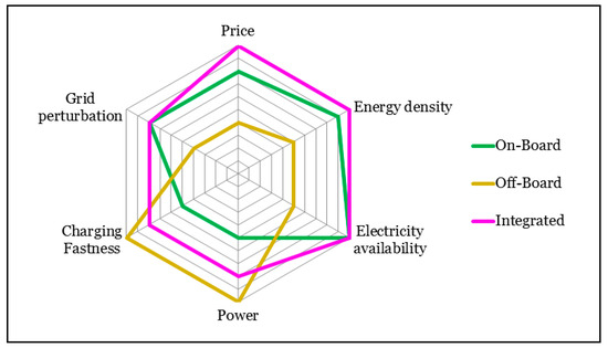
Figure 5.
Comparison between On-Board, Off-Board and Integrated chargers.
On-Board chargers are limited to level 1 and 2 (slow charging) because of cost, weight, and space constraints. Their main advantage is their capability to charge the batteries wherever a suitable power source, such as a household outlet [17], is available. This can increase the acceptance of Plug-in Electric Vehicles [9,18]. On-Board chargers used at home usually charge during the night, which has minimal impact on the supply grid [4], and they can facilitate the load level control of power utilities as the electricity demand at night is relatively low [1].
Another considered option for On-Board chargers consists of integrating the battery charger into the electric drive system of the PEV when traction and charging are not simultaneous, as in [4]. In this case, the motor windings serve as filter inductors and the motor inverter is used as a bidirectional AC/DC converter. Consequently, weight, volume and cost are minimized while faster charging (level 2 and 3) can be achieved [17,18]. In addition, these chargers are bi-directional by design [17,19]. However, the control complexity and extra hardware needed are challenges to overcome [11,18].
Off-Board chargers do not have space or weight constraints, and that is why they are capable to operate for fast charging. They take AC power from the grid and transform it to DC power that is then delivered to the vehicle [9,19]. Since the EV must include some power electronics for the traction, an Off-Board charger entails redundant power electronics and thus an extra cost. In addition, fast charging can overload the distribution network because of its high-power demand, typically larger than double of a household load [1,20]. Further disadvantages involve the risk of vandalism and extra clutter in an urban environment [4,11].
2.3. Unidirectional vs. Bidirectional Chargers
A battery charger is a device comprising one or more power electronics circuits that are used to convert electrical energy. These power converters are different depending on the direction of the power flow between the grid and the battery, the charging and discharging requirements of the battery and the grid parameters [18]. The power flow in a general charger’s structure can be unidirectional (G2V mode) or bidirectional (G2V and V2G modes), as depicted in Figure 6.
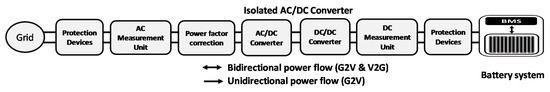
Figure 6.
Power flow in a general charger’s structure.
The unidirectional charger is the first one considered because of its simplicity, less hardware and interconnection requirements and less battery degradation [11]. However, as the power flows only from the grid to the vehicle, the services that the V2G application could provide are limited. The typical configuration comprises a diode bridge rectifier, a filter, and a DC/DC converter [22].
On the other hand, a bidirectional charger, even if more complicated, can provide further benefits to the electricity grid and higher quality ancillary services. The typical configuration comprises two stages: a bidirectional AC/DC converter in the grid side to control the current wave form and PF and a bidirectional DC/DC converter in the battery side to control the battery’s voltage, current or power, depending on its operation requirements [23,24].
The main differences between the two chargers are included in the following Table 3.
Table 3.
Comparison between unidirectional and bidirectional chargers [11,25].
2.4. Assessment of V2G and G2V Converter Topologies
Depending on the battery pack’s voltage, the EV’s charger can comprise different topologies:
1. High-Voltage Batteries
When a HV battery pack is used, only an AC/DC converter might be utilized to connect it to the grid. The following Figure 7 and Table 4 present the main topologies that could be used. Only single-phase bidirectional structures have been considered for AC, but it could be adapted to three-phase structures for high power applications.
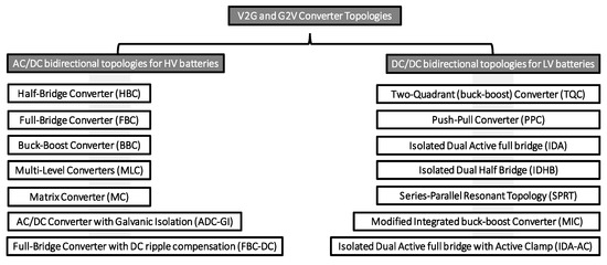
Figure 7.
AC/DC and DC/DC topologies for HV and LV battery systems.
Table 4.
Comparison of AC/DC Converters for HV Battery connection.
2. Low-Voltage Batteries
On the contrary, when LV batteries are used, there must be an intermediate DC/DC converter to boost the voltage to the needed value in de DC-Bus [6]. LV Batteries can recuperate more energy from the DC-Bus during the regenerative braking mode [26]. The mainly used topologies are stored in Table 5.
Table 5.
Comparison of DC-DC Converters for LV-Battery connection.
There exist some options, such us interleaving, soft switching, multilevel and resonant tanks that could be implemented to increase the efficiency and improve the functionality of the converters [11]. Nowadays, European Committees like CENELEC recommend the installation of a galvanic isolation between the grid and the local sources that use power converters, such as renewable generators or electric vehicles [27]. Normally this galvanic isolation is provided by a High Frequency (HF) transformer [28] located in the DC/DC converter.
In the presented topologies, MOSFETs are employed for low power, IGBTs for medium power and GTOs for high power applications [23].
3. Modeling and Control of V2G and G2V Systems
The V2G technology can provide numerous benefits to the electricity grid as long as a good control is implemented. It is essential to establish a charging and discharging methodology to control the energy taken or given to the battery. This methodology generates the grid current reference for an internal and faster grid current control loop that establishes the switching patterns for the converter, to control the energy given or taken from the grid. The reference current is synchronized to the grid voltage using a PLL. The block diagram of the control is depicted in Figure 8.
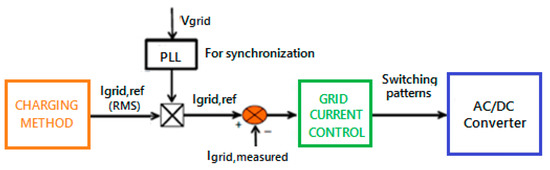
Figure 8.
Main control blocks in the system.
The three main charging and discharging methodologies are the following [35,36,37].
1. Constant Voltage Charging (CV)
This technique uses the value of the highest voltage (corresponding to the totally charged battery) during the whole charging process. The current is unconstrained, so at the beginning, its value is high, and it decreases as the battery is charging [36].
2. Constant Current Charging (CC)
With this methodology, as explained in [35,37], the current applied is constant and the voltage increases while the battery charges. If the battery’s impedance is not zero, the battery does not totally charge.
3. Combined Charging CC-CV
The combined CC-CV charging is the method commonly used for lithium batteries since it enables a complete charging without any overcharge [26]. The first stage of this method, as described in [36], consists on CC charging until the voltage achieves its highest value. Once this value is reached, CV charging is done, maintaining the voltage at its maximum value while the current starts to reduce until it reaches a certain value for which the battery is considered totally charged.
The control blocks and Current and Voltage curves during the implementation of these methodologies are represented in Figure 9.
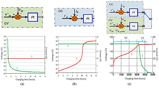
Figure 9.
Charging methodologies control blocks and Voltage-Current Curves. (a) CV Charging; (b) CC Charging; (c) CC-CV Charging.
On the other hand, the grid current loop can be performed using different control techniques. These techniques are known as Vehicle-to-Grid control strategies and they are responsible for the power flow management for charging (G2V) or discharging (V2G) operating modes [6]. Three different strategies are presented below, and their block diagrams are shown in Figure 10:
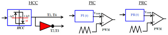
Figure 10.
Block diagram of the V2G control strategies.
1. Hysteresis Current Control (HCC)
The hysteresis-band current control is an instantaneous feedback current technique where the switching patterns are generated using a hysteresis band [15,29]. As it has variable switching frequency, the losses are higher than with other strategies [26,38].
2. Proportional-Integral Control (PIC)
The Proportional-Integral Control uses a PI Controller, whose transfer function is expressed in Equation (1), where Kp and Ki are the proportional and integral gains of the loop. This controller acts continuously, so it is more accurate than the previous method. The switching frequency is constant and equal to the frequency of the triangular signal used for the Pulse-Width-Modulation (PWM). This fact improves the efficiency of the charger. On the other hand, the main problem of this controller is that it cannot do a perfect tracking of the reference.
3. Proportional-Resonant Controller (PRC)
The Proportional-Resonant Controller (PRC) is similar to a conventional PI, but with a theoretical infinite gain at a given resonant frequency, so that it can make the error at that frequency equal to zero, enhancing a good reference tracking [15,29,39]. Its transfer function is expressed in Equation (2), where Kp determines the dynamic response of the system, Ki adjusts the phase shift between the output and the reference signals and is the resonant frequency [6,26].
In this paper, the grid current loop comprises a PI controller, a filter and a sensor, a delay to model the digitalization, and the FB converter. The open-loop transfer function, in s-domain, can be seen in Equation (3).
The first step in the design of a control strategy consists on simplifying the real systems to simple linear systems, to which the Classical Control Theory can be applied [40]. Afterwards, the stability of the loop must be assessed using Bode Plots and Root Locus techniques, with which the controllers’ parameters are calculated.
For this current loop, the Bode Plots for different cross-over frequencies and Phase Margins were depicted, as in Figure 11. Afterwards, the Step Response of the loop, for the same parameters, were plotted as in Figure 12. It was concluded that the best option was to use 1000 Hz for cross-over frequency and 45° as phase margin. Finally, once these two values are settled, the PI controller parameters, Ki, Kp, and Tn are calculated with Equations (4)–(6).

Figure 11.
Bode Plots of the Grid Current Loop for various fc and PM.
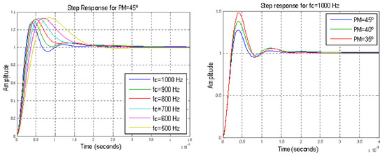
Figure 12.
Step Response of the Grid Current Loop for various fc and PM.
The Simulink model of this grid current control, for Light-Duty vehicles, is depicted in Figure 13. For Heavy-Duty Vehicles, each phase of the grid current is controlled with a separate loop.
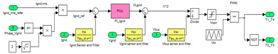
Figure 13.
Simulink model of the grid current control for Light-Duty Vehicles.
3.1. V2G and G2V Systems for Light-Duty (LD) Vehicles
In this part, V2G and G2V systems for Light-Duty (LD) Vehicles have been analyzed. Two bidirectional single-phase 3.3 kW chargers have been simulated by using Matlab/Simulink (see Figure 14 and Figure 15). Among the available battery technologies, the current two main battery technologies used in EVs are nickel metal-hydride (NiMH) and lithium-ion (Li-ion). Due to the potential of obtaining higher specific energy and energy density, the adoption of Li-ion batteries is expected to grow fast in EVs, particularly in PHEVs and BEVs. Therefore, this research study focused on Li-ion batteries [41].
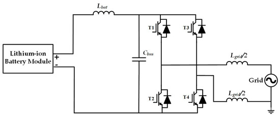
Figure 14.
Simulink model of the FB for Light-Duty Vehicles.

Figure 15.
Simulink model of the FB and the Two-Quadrant converter for Light-Duty Vehicles.
The first charger consists of an AC/DC converter connected to High Voltage (HV) batteries, is depicted in Figure 14. A Full Bridge has been used for its simplicity and good operation. As reported in [10], this converter is composed by two commutation branches, each comprising two complementary switches, T1–T2 and T3–T4, with which 4 different commutation states can be achieved. The combination of these states provides the desired output voltage wave form. Bipolar modulation is implemented, and the grid inductor is divided in two to minimize the common mode currents [10]. The main parameters of this circuit are stored in Table 6.
Table 6.
Main characteristics of the Light-Duty system connected to HV Batteries.
The second charger counts with the addition of a DC/DC converter to connect to Low Voltage (LV) Batteries. The topology chosen for this DC/DC converter is Two-Quadrant, as seen in Figure 15, and its main parameters are stored in Table 7. In fact, the Two-Quadrant converter consists on having a unidirectional Boost or Buck converter in which the switches are bidirectional, composed by a transistor with a diode in antiparallel, as in [42].
Table 7.
Main characteristics of the Light-Duty system connected to LV Batteries.
3.2. V2G and G2V Systems for Heavy-Duty (HD) Vehicles
Afterwards, V2G and G2V systems for Heavy-Duty (HD) Vehicles have been studied, where two bidirectional three-phase 22 kW chargers are simulated by using Matlab/Simulink.
As in the previous case, the first topology consists on an AC/DC converter. The chosen topology, as seen in Figure 16, is a Full-Bridge with three commutation branches, as the grid has three phases [43]. The main parameters are stored in Table 8.
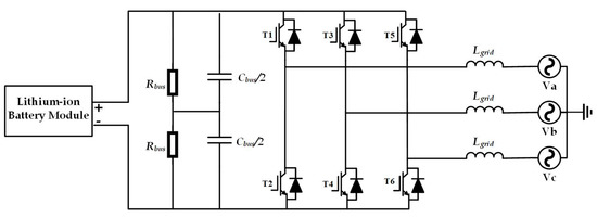
Figure 16.
Simulink model of the FB for Heavy-Duty Vehicles.
Table 8.
Main characteristics of the Heavy-Duty system connected to HV Batteries.
For using Low Voltage (LV) Batteries, the second topology’s DC-Bus has been connected to a Two-Quadrant converter. It is depicted in Figure 17 and its main parameters are stored in Table 9.

Figure 17.
Simulink model of the FB and the Two-Quadrant converter for Heavy-Duty Vehicles.
Table 9.
Main characteristics of the Light-Duty system connected to LV Batteries.
4. Results and Discussion
Once the models of the converters and their controls have been designed and implemented in Matlab/Simulink, some tests have been performed to check their correct operation. First of all, the grid current and voltage are depicted in Figure 18, both for Light-Duty and Heavy-Duty Vehicles. It can be seen than the PFC is working properly; when charging, both waves are in phase, whereas in V2G mode they have a phase difference of 180°.
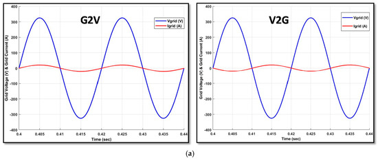
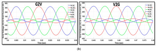
Figure 18.
Grid Voltage and Current in G2V and V2G systems. (a) Single Phase for Light-Duty Vehicles; (b) Three Phase for Heavy-Duty Vehicles.
Special attention has been paid to the harmonics in both the AC current and voltage. In particular, for the first topology implemented, consisting on just an AC/DC converter for Light-Duty systems, the FFT analysis is presented in Figure 19. It must be noted that the DC current to the grid is quite high, so introducing a transformer in the charger’s structure may be considered. It is also essential to remark that the THD for both V2G and G2V modes is the same.

Figure 19.
Harmonic content of the grid current for Bipolar Modulation. (a) Charging mode; (b) Discharging mode.
An option to reduce the current harmonics is the use of unipolar instead of bipolar modulation. The results obtained with it are shown in Figure 20. It is clear that the THD has been reduced from 2.88% for bipolar to 0.90% for unipolar, using the same output filter. Moreover, the DC current is also reduced significantly.

Figure 20.
Harmonic content of the grid current in charging mode for Unipolar Modulation.
On the battery side, when G2V mode is being implemented, the voltage, power and SoC of the battery pack increases. On the contrary, when V2G mode is operating, they decrease. Figure 21 shows these parameters for the first topology analyzed, with Constant Current (CC) methodology. It is visible that there exists a 100 Hz ripple in the waves which is not beneficial for the battery, since it could be seen as using a pulsing charging methodology which may affect the State of Health and life span of the battery. The addition of a DC/DC converter, as in the second topology, eliminates this ripple.

Figure 21.
Battery Curves in G2V and V2G systems. (a) Charging: G2V; (b) Discharging: V2G.
To check the flexibility of the control implemented, Figure 22 shows the transition between charging and discharging modes for the first topology. It can be noted that the system reacts very fast in the grid side, whereas the battery side is slower. Similarly, Figure 23 shows transitions for the third topology, consisting on an AC/DC converter for Heavy-Doty Vehicles. In this case, the battery stabilization is faster, as the 100 Hz ripple has disappeared.
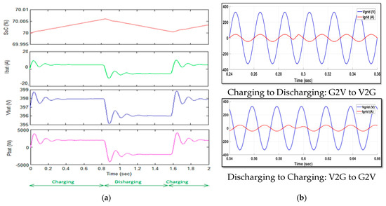
Figure 22.
Transitions in the operation mode for Light-Duty Vehicles. (a) Battery Curves; (b) Grid Current and Voltage.

Figure 23.
Transitions in the operation mode for Heavy-Duty Vehicles. (a) Battery Curves; (b) Grid Current and Voltage.
5. Comparative Study
A FFT Analysis has been performed for the four topologies developed. The THD of both the AC current and voltage can be seen in Figure 24. In all cases, both G2V and V2G modes have the same level of harmonics. It must be highlighted that the voltage harmonics are reduced to half their value for three-phase, Heavy-Duty systems.
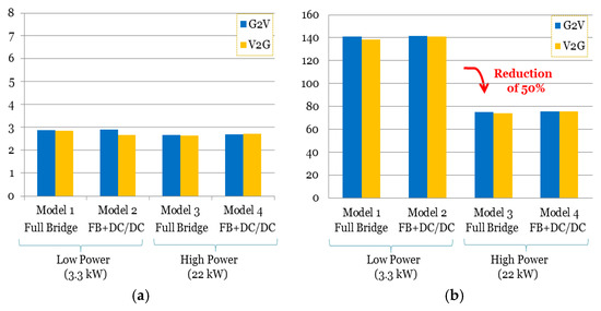
Figure 24.
Total Harmonic Distortion of the AC waves in the four studied topologies. (a) Grid Current THD; (b) AC Voltage THD.
Finally, a 24-kWh electric vehicle was experimentally analyzed to see the operation of the G2V technology in a real environment. Three different measurements of the State-of-Charge (SoC), Power, Voltage, Current, Power Factor (PF) and Deformation Factor (DF) were taken while the vehicle was charging and they are stored in Table 10. Furthermore, the current and voltage provided at the same time of the measurements are depicted in Figure 25, where signal A is the current and signal B is the voltage.
Table 10.
Measured data from a 24-kWh electric vehicle while charging.
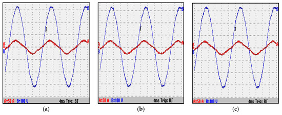
Figure 25.
Current and voltage supplied to a 24 kWh electric vehicle at various SoC. (a) SoC = 17%; (b) SoC = 31%; (c) SoC = 42%.
In all cases, the power factor is capacitive; this means the current leads the voltage. The value of this PF is very good, very close to 1. It can be noted that as the SoC increases, the voltage does too for the NMC battery. This always happens in this kind of electrochemical systems, where the voltage is higher as the system is more charged. Moreover, it has to be noted that for G2V operation, the results from the simulations are very similar to the real ones. Therefore, as positive results were obtained for the V2G operation in the simulation, it can be concluded that the results in a real environment would also be favorable.
6. Conclusions
The main research topics of this paper were the design and assessment of four topologies, for both Light-Duty and Heavy-Duty Vehicles, with which the G2V and V2G concepts have been tested. Bipolar modulation was utilized for its easy implementation and almost constant common mode voltage, which enables a transformer-less system. Nevertheless, simulations have shown that the DC currents are very high, so that the installation of a transformer is mandatory to avoid the saturation of the grid’s transformers.
The results for Heavy-Duty Vehicles have shown that obtaining the AC voltage from a higher amount of voltage levels reduces its THD. Thus, the use of multilevel converters could be contemplated. Furthermore, the harmonic content in the topologies is very similar. This means that the addition of a DC/DC converter, which provides better control options and enables the use of LV Batteries, does not affect the quality of the power given to or taken from the grid. In addition, it attenuates the 100 Hz oscillation appearing in the battery side for low power applications.
Finally, the results of the simulations have been compared to some measurements taken from a real Electric Vehicle while charging. As the parameters and waves obtained are very similar for the G2V mode, it can be concluded that they will also be very similar for the V2G mode. The simulations proved that both G2V and V2G operations have the same perturbation on the electricity grid. Therefore, since G2V is nowadays being implemented, we conclude that the V2G mode could be also implemented and provides its inherent benefits to the grid.
Author Contributions
M.G.Q. performed the modeling and design of selected the topologies and wrote the first version of the paper; M.A.-M. contributed in the review of the high-power charging topologies and in their control design, and he reconstructed the structure of the paper, and he contributed in writing the final version of the paper. M.E.B. and Y.Y. contributed in reviewing and designing the inductive systems as well as performing the experimental tests for vehicles. J.V.M. contributed in analyzing the results and editing the paper. O.H. contributed in designing and control modeling of the charging topologies, especially for topologies based on DC/DC converters, and he is leads this research study as a promoter and edits the manuscript.
Acknowledgments
We acknowledge Flanders Make for supporting our team.
Conflicts of Interest
The authors declare no conflict of interest.
Abbreviations
| Electric vehicle | |
| Grid-to-vehicle | |
| Vehicle-to-grid | |
| Plug-in electric vehicles | |
| Plug-in hybrid vehicles | |
| OCV | Open Circuit Voltage |
| SoC | State-of-Charge (%) |
| Constant current | |
| Constant voltage | |
| Phase locked loop | |
| High voltage | |
| EMC | Electromagnetic compatibility |
| LV | Low voltage |
| CENELEC | European committee for electrotechnical standarization |
| MOSFET | Metal-oxide-semiconductor field-effect transistor |
| IGBT | Insulated-gate bipolar transistor |
| GTO | Gate Turn-Off Switch |
| THD | total harmonic distortion |
| FFT | Fast Fourier transform |
References
- Chan, C.C.; Chau, K.T. An overview of power Electronics in electric vehicles. IEEE Trans. Ind. Electron. 1997, 44, 3–13. [Google Scholar] [CrossRef]
- Darabi, Z.; Ferdowsi, M. Aggregated Impact of Plug-In Hybrid Electric Vehicles on Electricity Demand Profile. IEEE Trans. Sustain. Energy 2011, 2, 319–349. [Google Scholar] [CrossRef]
- Wirasingha, S.G.; Emadi, A. Pihef: Plug-in hybrid electric factor. IEEE Trans. Veh. Technol. 2011, 60, 1279–1284. [Google Scholar] [CrossRef]
- Habib, S.; Kamran, M.; Rashid, U. Impact analysis of vehicle-to-grid technology and charging strategies of electric vehicles on distribution networks—A review. J. Power Sources 2015, 277, 205–214. [Google Scholar] [CrossRef]
- Sandalow, D.B. Plug-In Electric Vehicles: What Role for Washington? 1st ed.; Brookings Institution Press: Washington, DC, USA, 2009. [Google Scholar]
- Hegazy, O.; Van Mierlo, J.; Barrero, R.; Lataire, P.; Omar, N.; Coosemans, T. A comparative study of different control strategies of On-Board Battery Chargers for Battery Electric Vehicles. In Proceedings of the Eighth International Conference and Exhibition on Ecological Vehicles and Renewable Energies (EVER), Monte Carlo, Monaco, 27–30 March 2013; pp. 1–6. [Google Scholar]
- Yilmaz, M.; Krein, P.T. Review of benefits and challenges of vehicle-to-grid technology. In Proceedings of the IEEE Energy Conversion Congress and Exposition (ECCE), Raleigh, NC, USA, 15–20 September 2012; pp. 3082–3089. [Google Scholar]
- Keane, E.; Flynn, D. Potential for electric vehicles to provide power system reserve. In Proceedings of the IEEE PES Innovative Smart Grid Technologies (ISGT), Washington, DC, USA, 16–20 January 2012; No. 9. pp. 1–7. [Google Scholar]
- Markel, T. Plug-in Electric Vehicle Infrastructure: A Foundation for Electrified Transportation; NREL/CP-540-47951; NREL: Washington, DC, USA, 2010; pp. 1–10. [Google Scholar]
- Barrios, E. Unit 3: Conversion Stage in Single-Phase Photovoltaic Systems; UPNA: Pamplona, Spain, 2015. [Google Scholar]
- Yilmaz, M.; Krein, P.T. Review of battery charger topologies, charging power levels and infrastructure for plug-in electric and hybrid vehicles. IEEE Trans. Power Electron. 2013, 28, 2151–2169. [Google Scholar] [CrossRef]
- Chopra, S. Contactless Power Tranfer for Electric Vehicle Charging Application. Master’s Thesis, Delft University of Technology, Delft, The Netherlands, 2011. [Google Scholar]
- Bauer, P. Contactless Power Transfer: Inductive Charging of EV. Master’s Thesis, Delf University of Technology, Delft, The Netherlands, 2010. [Google Scholar]
- Mi, C. Safely Charging EV and PHEV from the Electricity Grid: Introduction to EV/PHEV; University of Michigan-Dearborn: Dearborn, MI, USA, 2015; No. 313. [Google Scholar]
- Lin, B.; Member, I.; Chen, D.; Tsay, H. Bi-Directional AC/DC Converter based on neutral point clamped. In Proceedings of the IEEE International Symposium on Industrial Electronics, Pusan, Korea, 12–16 June 2001; pp. 1–6. [Google Scholar]
- Miskiewicz, R.M.; Moradewicz, A.J.; Kazmierkowski, M.P. Contactless battery charger with bi-directional energy transfer for plug-in vehicles with vehicle-to-grid capability. In Proceedings of the IEEE International Symposium on Industrial Electronics, Gdansk, Poland, 27–30 June 2011; pp. 1969–1973. [Google Scholar]
- Solero, L. Nonconventional on-board charger for electric vehicle propulsion batteries. IEEE Trans. Veh. Technol. 2001, 50, 144–149. [Google Scholar] [CrossRef]
- Kisacikoglu, M.C.; Ozpineci, B.; Tolbert, L.M. Examination of a PHEV bidirectional charger system for V2G reactive power compensation. In Proceedings of the Twenty-Fifth Annual IEEE Applied Power Electronics Conference and Exposition (APEC), Palm Springs, CA, USA, 21–25 February 2010; pp. 458–465. [Google Scholar]
- Botsford, C.; Szczepanek, A. Fast Charging vs. Slow Charging: Pros and cons for the New Age of Electric Vehicles. In Proceedings of the EVS24 International Battery, Hybrid and Fuel Cell Electric Vehicle Symposium, Stavanger, Norway, 13–16 May 2009; pp. 1–9. [Google Scholar]
- Shireen, W.; Patel, S. Plug-in hybrid electric vehicles in the smart grid environment. In Proceedings of the IEEE PES Transmission and Distribution Conference and Exposition, New Orleans, LA, USA, 19–22 April 2010; pp. 1–4. [Google Scholar]
- Tang, L.; Su, G.-J. A low-cost, digitally-controlled charger for plug-in hybrid electric vehicles. In Proceedings of the IEEE Energy Conversion Congress and Exposition, San Jose, CA, USA, 20–24 September 2009; pp. 3923–3929. [Google Scholar]
- Singh, B.; Singh, B.N.; Chandra, A.; Al-Haddad, K.; Pandey, A.; Kothari, D.P. A review of three-phase improved power quality ac-dc converters. IEEE Trans. Ind. Electron. 2004, 51, 641–660. [Google Scholar] [CrossRef]
- Singh, B.; Singh, B.N.; Chandra, A.; Al-Haddad, K.; Pandey, A.; Kothari, D.P. A Review of Single-Phase Improved Power Quality AC–DC Converters. IEEE Trans. Ind. Electron. 2003, 50, 962–981. [Google Scholar] [CrossRef]
- Zhou, X.; Lukic, S.; Bhattacharya, S.; Huang, A. Design and control of grid-connected converter in bi-directional battery charger for plug-in hybrid electric vehicle application. In Proceedings of the IEEE Vehicle Power and Propulsion Conference (VPPC ’09), Dearborn, MI, USA, 7–10 September 2009; pp. 1716–1721. [Google Scholar]
- Thiringer, T.; Grenier, M.; Aghdam, M.G.H. Design of on-board charger for plug-in hybrid electric vehicle. In Proceedings of the 5th IET International Conference on Power Electronics, Machines and Drives (PEMD 2010), Brighton, UK, 19–21 April 2010; p. 152. [Google Scholar]
- Hegazy, O.; El Baghdadi, M.; Van Mierlo, J.; Lataire, P. Modeling and analysis of different control techniques of conductive battery chargers for electric vehicles applications. COMPEL Int. J. Comput. Math. Electr. Electron. Eng. 2015, 34, 151–172. [Google Scholar] [CrossRef]
- Focus Group on European Electro-Mobility. Standardization for Road Vehicles and Associated Infrastructure—Report in Response to Commision Mandate M/468 Concerning the Charging of Electric Vehicles. October 2011, p. 155. Available online: esci-ksp.org/publication/focus-group-on-european-electro-mobility-standardization-for-road-vehicles-and-associated-infrastructure-report-in-response-to-commission-mandate-m468-concerning-the-charging-of-electric-vehicles/ (accessed on 26 April 2018).
- Karshenas, H.R.; Daneshpajooh, H.; Safaee, A.; Jain, P.; Bakhshai, A. Bidirectional DC-DC Converters for Energy Storage Systems. In Energy Storage Emerging Era Smart Grids; InTech: London, UK, 2011; pp. 161–178. [Google Scholar]
- Erb, D.C.; Onar, O.C.; Khaligh, A. Bi-directional charging topologies for plug-in hybrid electric vehicles. In Proceedings of the Twenty-Fifth Annual IEEE Applied Power Electronics Conference and Exposition (APEC), Palm Springs, CA, USA, 21–25 February 2010; pp. 2066–2072. [Google Scholar]
- Koushki, B.; Safaee, A.; Jain, P.; Bakhshai, A. A Bi-Directional Single-Stage Isolated AC-DC Converter for EV charging and V2G. In Proceedings of the IEEE Electrical Power and Energy Conference (EPEC), London, ON, Canada, 26–28 October 2015; pp. 36–44. [Google Scholar]
- Bell, B. Introduction to Push-Pull and Cascaded Power Converter Topologies; National Semiconductor: Santa Clara, CA, USA, 2003; pp. 1–44. [Google Scholar]
- Du, Y.; Lukic, S.; Jacobson, B.; Huang, A. Review of high power isolated bi-directional DC-DC converters for PHEV/EV DC charging infrastructure. In Proceedings of the IEEE Energy Conversion Congress and Exposition (ECCE), Phoenix, AZ, USA, 17–22 September 2011; pp. 553–560. [Google Scholar]
- Garcés, M.; Alonso, M. Resonant Power Converter for Fuel Cells: Analysis, Design and Simulation; Public University of Navarra: Pamplona, Spain, 2014. [Google Scholar]
- Li, H.; Member, S.; Peng, F.Z.; Member, S.; Lawler, J.S.; Member, S. A Natural ZVS High-Power Bidirectional DC–DC Converter with Minimum Number of Devices. IEEE Trans. Ind. Appl. 2003, 39, 525–535. [Google Scholar] [CrossRef]
- Ursua, A. Unit C: Electrochemical Systems: Basic Aspects about Batteries; UPNA: Pamplona, Spain, 2015. [Google Scholar]
- Abdel-Monem, M.; Trad, K.; Omar, N.; Hegazy, O.; Mantels, B.; Mulder, G.; van den Bossche, P.; van Mierlo, J. Lithium-ion batteries: Evaluation study of different charging methodologies based on aging process q. Appl. Energy 2015, 152, 143–155. [Google Scholar] [CrossRef]
- Abdel-Monem, M.; Trad, K.; Omar, N.; Hegazy, O.; van den Bossche, P.; van Mierlo, J. Influence analysis of static and dynamic fast-charging current profiles on ageing performance of commercial lithium-ion batteries. Energy 2017, 120, 179–191. [Google Scholar] [CrossRef]
- Marschalko, R.; Elöd, C. PWM AC-to-DC Converter Performances Improvement with the Help of Hysteresis Control. Acta Electroteh. 2004, 45, 561–567. [Google Scholar]
- Hegazy, O.; van Mierlo, J.; Lataire, P. Design and Control of Bidirectional DC/AC and DC/DC Converters for Plug-In Hybrid Electric Vehicles. In Proceedings of the International Conference on Power Engineering, Energy and Electrical Drives (POWERENG), Malaga, Spain, 11–13 May 2011; pp. 1–7. [Google Scholar]
- Barrios, E. Unit 4: Control of the Photovoltaic Conversion Stage; UPNA: Pamplona, Spain, 2015. [Google Scholar]
- Abdel-Monem, M.; Hegazy, O.; Omar, N.; Trad, K.; de Breucker, S.; van den Bossche, P.; van Mierlo, J. Design and Analysis of Generic Energy Management Strategy for Controlling Second-Life Battery Systems in Stationary Applications. Energies 2016, 9, 889. [Google Scholar] [CrossRef]
- Bhardwaj, M. Modeling Bi-Directional Bcuk/Boost Converter for Digiteal Control Using C2000 Microcontrollers; Application Report SPRABX5; Texas Instruments Inc.: Dallas, TX, USA, 2015; pp. 1–12. [Google Scholar]
- Marroyo, L. Three-Phase Inverter: Sizing and Scalar Control; UPNA: Pamplona, Spain, 2015. [Google Scholar]
© 2018 by the authors. Licensee MDPI, Basel, Switzerland. This article is an open access article distributed under the terms and conditions of the Creative Commons Attribution (CC BY) license (http://creativecommons.org/licenses/by/4.0/).