1. Introduction
Among renewable energies, wind energy conversion systems (WECSs) are some of the most relevant, with more than 432 GW installed by 2015 [
1]. Research and integration of wind turbines (WTs) and voltage-sourced converters (VSCs) have increased the possibilities for application of wind energy and improved its controllability [
2].
Control and operation of WECSs have been widely studied in the literature. Mainly, these studies have focused on grid-connected operations, [
3,
4,
5], lately including grid-supporting functions such as frequency support [
6,
7].
The system proposed in the paper differs from the classical application of WECSs in that it is not designed to extract the available wind power but to supply the power demanded by the load. In such situations, the proposed control system ensures that the WECS can supply the demand without the need for additional power sources.
One of the first studies concerning the supply of an isolated load from a WECS was carried out by [
8] employing a doubly-fed induction generator (DFIG). Further studies on this topic, when the generator is connected to an unbalanced system, have been published by the same research group [
9,
10]. While in these studies an indirect flux control was proposed, in [
11] a direct flux control is employed. DFIGs have also been successfully included in more complex microgrid systems through the use of droop control systems [
12].
However, there has been little research about full converter (FC)-based WECSs, where the role of the power converters changes significantly compared to DFIGs [
13]. Moreover, since standalone applications usually require low to medium power WECSs, FC solutions using permanent magnet synchronous generators (PMSGs) and squirrel-cage induction generators (SCIGs) seem more suitable than DFIGs [
14,
15].
FC stand-alone control systems are proposed in [
16,
17,
18,
19,
20]. In [
16], the GSC is controlled using a maximum power point tracking (MPPT) strategy, while the line side converter (LSC) controls the DC voltage. Power balance is achieved by a dump resistor connected at the DC bus. In [
17] and [
18] the voltage control is performed in an open loop and there is no control of the inverter current. Moreover, in these studies the effect of wind variation on the load balancing is not analysed. A similar study is presented in [
19] but employing a current-sourced converter. This scheme is analysed in [
20] for sudden unbalanced operating conditions when feeding three isolated single phase loads.
Most studies related to isolated operation have focused primarily on the generator control through laboratory testing using a primary mover capable of supplying power whenever it is demanded by the isolated load. However, in a real standalone operation of a WECS, a key concern is how to balance generation and load. To face this problem several authors have suggested the integration of more than a source [
21,
22,
23,
24,
25] in the so-called hybrid systems, where energy storage systems (ESSs) and diesel generators play a significant role in power balancing. In [
21] a FC system is connected in parallel to a battery ESS with little insight in the voltage and frequency control (VFC). The WECS is commanded to follow a MPPT strategy and the ESS performs the power balance. In [
22] the diesel generator is replaced by a photovoltaic (PV) system. A small battery ESS and a dump load are used to balance power. In [
23] the isolated system is fed through a fixed speed WT and a battery ESS.
In this paper, a different approach is presented. The roles of the converters in the WECS are inverted from usual FC applications so the WECS LSC controls AC voltage and frequency while the generator side converter (GSC) is responsible for maintaining constant voltage in the DC link. Also, instead of using a dummy load or an additional power source, as in hybrid systems, power balance is achieved by the speed regulation of the WT through pitch angle control.
On top of that, a VFC is proposed, based on the orientation of the output voltage vector along a synchronous axis rotating at the reference frequency. The ability of the VFC to maintain the stator voltage oriented toward the synchronous reference axis means that constant voltage and frequency are obtained, which in turn means that the demanded active and reactive powers are supplied by the FC. In order to implement such principles, a new approach is proposed in this paper where the variations in the LSC filter capacitor voltage will provide the information needed for balancing active and reactive power in the isolated system. The LSC currents are also controlled to avoid large excursions and protect the converter against overcurrents [
26].
In
Section 2, dynamic models of the different elements are presented. Using these models, in
Section 3 the proposed control strategies are explained. The proposed system dynamics and stability are analysed in
Section 4.
Simulation results, using both the state-space model and a detailed switching model in PSIM are presented and discussed in
Section 5 to demonstrate the capabilities and contributions of the proposed control scheme. Experimental results on a real-time test bench have also been obtained for further demonstration of the control operation.
2. System Model
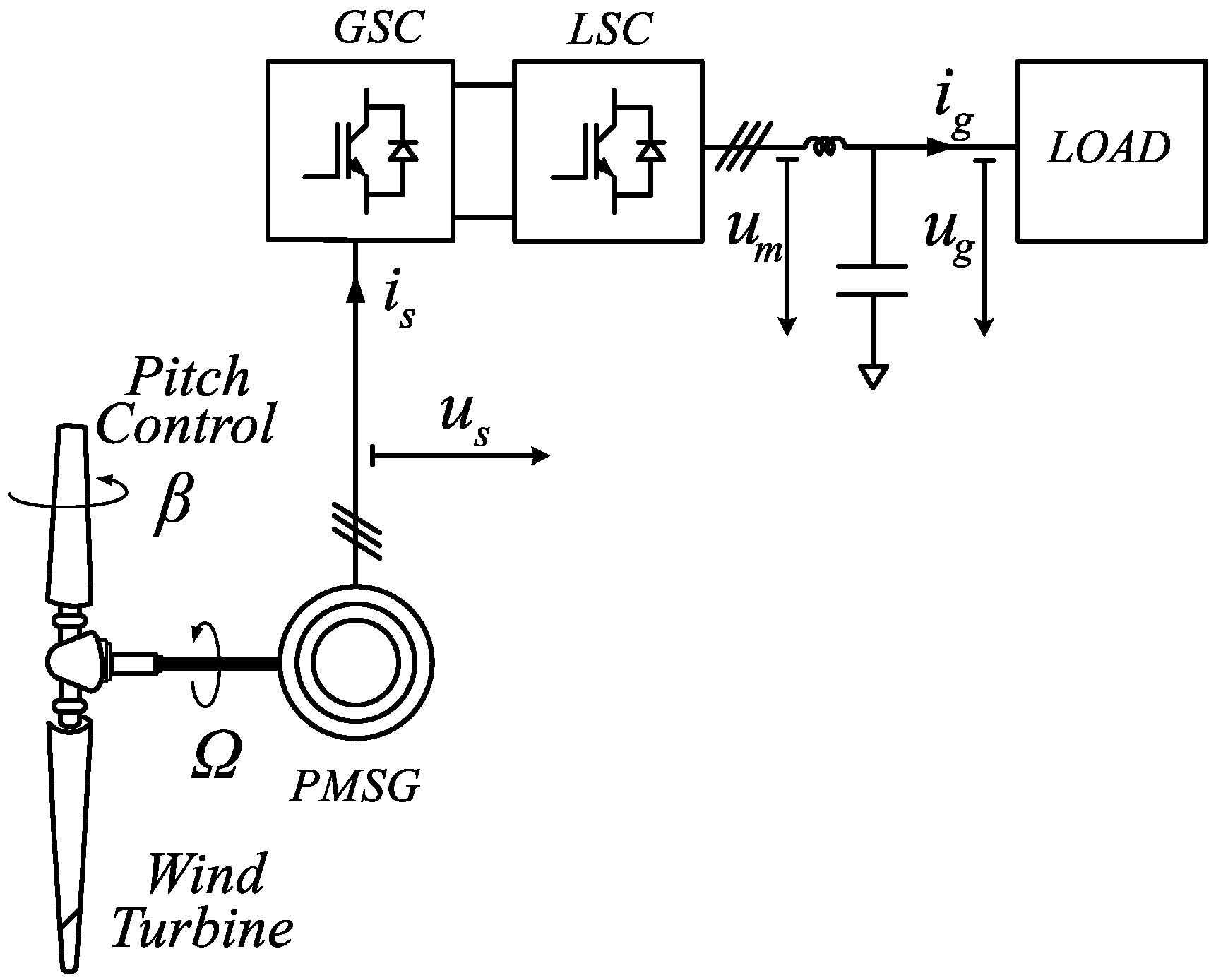
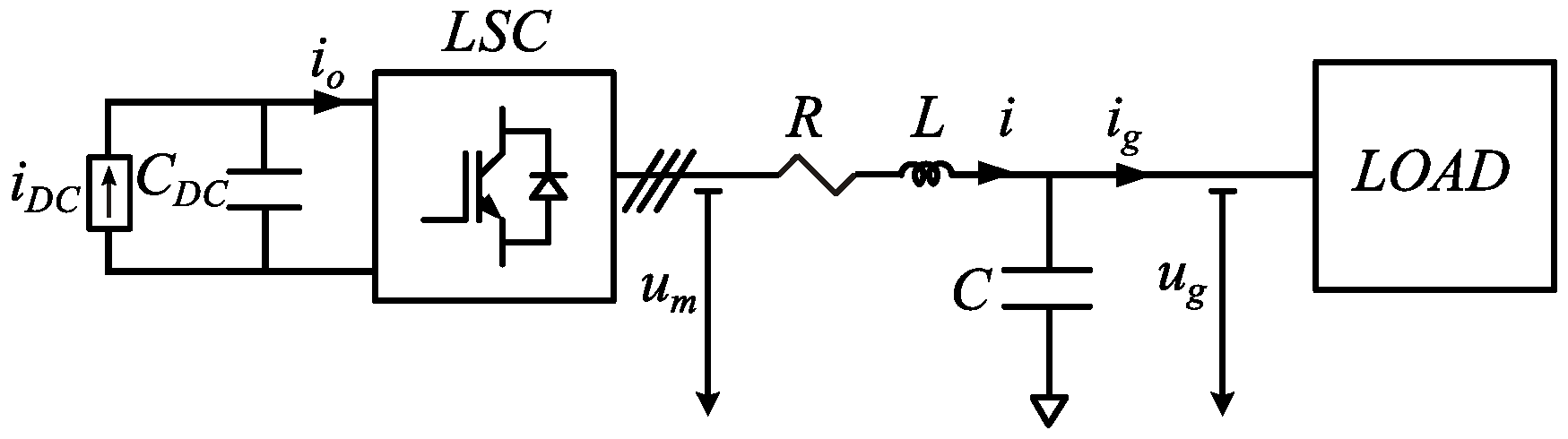
To properly understand the system behaviour, mathematical models of the different components of the system are presented. A scheme of the system is presented in
Figure 1 which includes the WT, the PMSG, the back-to-back converter, and the isolated load.
The system model is divided in three subsections. First, in the WT model, the relationship between the blade pitch angle
and the WT power and rotational speed will be illustrated. Then, the PMSG model will serve as a basis for the GSC control, responsible for maintaining constant DC link voltage despite variations in the generator voltage and frequency. Finally, the front-end converter is modelled in the state space. This model will be used later in
Section 3 to derive the VFC.
2.1. Wind Turbine Model
The aerodynamic model is based on the power characteristics of the WT. The mechanical power of the turbine is given by the equation
where
is the air density,
A is the WT rotor area,
v is the wind velocity, and
is the power coefficient of the WT, which is a function of the tip speed ratio,
, and the blade pitch angle,
. A generic equation was used to model the function
. This equation is based on the turbine characteristics of [
27].
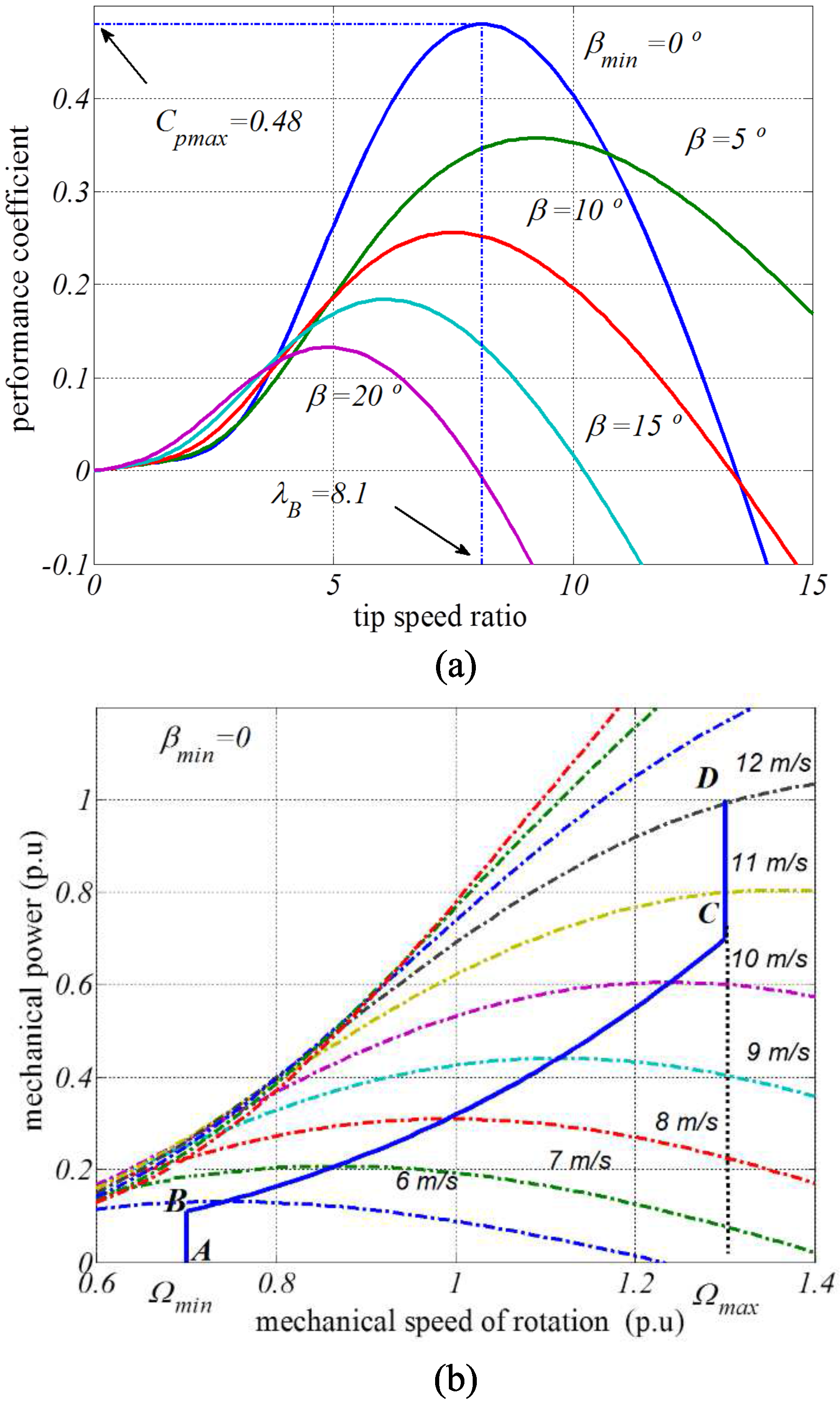
The relationship between the power coefficient and the tip speed ratio for various pitch angles can be seen in
Figure 2a. This figure shows how
affects
and therefore the WT power, meaning that
can be used for controlling the WT power. In most of the literature related to WECSs, this relation is employed to limit the power extracted at high wind speeds. However, as will be shown in
Section 3.1, in this work this relation is used to achieve the power balance by a load following strategy.
From the
relationship at constant
,
Figure 2b shows the WT power characteristics (WT power vs. WT rotational speed
), for different wind speeds. More importantly, this figure also shows the maximum power loci, which are obtained when the WT is operated with the maximum power coefficient,
, at
and
. As it will be shown in
Section 3.3, the maximum power curve is particularly relevant because it defines the steady-state stability limit of the WT. If the demanded power is increased beyond this curve, the subsequent reduction in the rotational speed will lead to a further reduction of the WT power, making the system unstable. This curve will be used in the control strategy of the LSC to limit the maximum active power that the WECS can supply to guarantee a stable operation.
2.2. PMSG Model
The electrical behavior of a PMSG can be expressed in a stationary reference frame as
where subscript
s stands for stator,
and
are the stator voltage and current, respectively,
are the stator total magnetic flux linkage,
is the angular position of the rotor, and
and
the stator resistance and inductance, respectively.
Since the PMSG dynamics are significantly faster than the WT ones, a steady-state model can be used for illustrating their interaction. From Equation (
2) the steady state model of the PMSG can be obtained as
where
is the electrical angular speed, related to the rotational speed through the pole pair numbers
as
.
This expression shows that the stator voltage is a function of the WT speed. Thus, by keeping constant
through pitch control, as explained in
Section 3.1, the electromagnetic force,
emf, and voltage (
) will be constant as well. The stator voltage will vary with the power demand due to the current-dependent terms of Equation (
3).
In order to implement the previous strategy on a dynamic control system, a transformation to a
rotating frame oriented to the rotor is used. The orientation to the rotor results in steady-state constant values for the control variables. Applying this transformation to Equation (
2) leads to
For a balanced three-phase system, the output power can be calculated as
where the asterisk indicates the complex conjugate. Using Equations (
4)–(
6) the output power can also be expressed as
The term related to the stator resistance can be interpreted as power losses and thus the electromagnetic torque is derived as
Equation (
8) shows that torque can be controlled by means of the q-component of the stator current
.
In a grid-connected FC,
is regulated to control the rotational speed of the WT and in this way control the WT power. However, in the off-grid application power is imposed by the load and
will be used to balance the power at the DC bus. This means that this current component will be obtained by the DC voltage controller to maintain constant DC voltage, which in turns means that the generator supplies the power that is demanded by LSC to supply the load. This is further developed in
Section 3.2.
2.3. VSC Inverter Model
The AC-side of a VSC can be represented by a three-phase AC voltage source connected to the system through a interfacing reactor, modelled by its inductance
L and resistance
R [
28,
29,
30] as seen in
Figure 3.
The dynamics of the DC link have been modelled by a controlled current source
in parallel with the DC bus capacitor
. This is useful to study the effects of the VFC on the DC-link, considering the voltage control performed by the GSC that will be explained in
Section 3.2.
Using pulse-width modulation (PWM), the relation between DC and AC voltages can be expressed as
where
is the modulating signal corresponding to phase k [
29].
At the AC side, the total capacitance connected is represented by
C. This includes the high frequency filter, which is considered purely capacitive at the fundamental frequency [
31], and other capacitor banks connected at the point of common coupling (PCC). The VSC terminal voltage
and the capacitor bank voltage
are related by the equation:
where
is the converter current and subscript
k stands for the system phase (
).
The phase currents and voltages and the modulating signals can be expressed in a rotating dq reference frame as
,
,
,
and
, respectively. Therefore, Equation (
10) can be expressed in a synchronous dq reference frame, rotating at constant frequency
, as
As will be explained in
Section 3.3 , the voltage vector of the capacitor bank,
, will be oriented to this reference frame by controlling the current,
, by means of the internal voltage of the converter
.
On the other hand, at the capacitor bank, the voltage equations per phase are
where
is the phase
k current demanded by the load. By applying the Park transformation, the above equation can be expressed in a dq reference frame as
The load is modelled as a constant power source that demands active power
and a reactive power
. This introduces a non-linear relation between the controlled voltage
and the demanded current
. This relation can be expressed in a dq reference frame as
Finally, the dynamics on the DC-link capacitor considering the relationship between the VSC DC and AC variables is expressed as
where the last term is the derived from the active AC power, neglecting the VSC losses.
The complete system dynamic equations can be obtained by separating the real and imaginary parts of Equations (
11) and (
13). Moreover, these equations plus Equation (
16) can be expressed per unit as
Base values for per unit transformation have been selected considering the ratings of the PMSG used for the real-time implementation. They are presented in
Table 1.
In the rest of the paper, variables in per unit are shown in lower case and the subindex is omitted.
In conclusion, the system has five state variables,
,
,
,
and
, two external inputs,
and
, and three controlled inputs,
,
and
. The stability of the system will be analysed in
Section 4.
3. Control
The control system is divided into WT, GSC, and LSC control. The proposed control scheme must be able to maintain constant voltage and frequency at the generator terminals despite a variable wind energy source while delivering the demanded amount of active and reactive power.
3.1. Wind Turbine Power Control
In order to ensure a stable operation, the power demanded by the load must be equal to the power delivered by the WT. To achieve this, the WT power is controlled through pitch control.
For a given wind velocity, WT operation is only possible below a defined stability limit, as shown in
Figure 2b. By regulating rotational speed in isolated operation, pitch control allows for the supply a specific load in a wider range of wind velocities or alternatively to deliver a wider range of power values for a specific wind velocity.
The generator power being fixed by the electrical load power, the mechanical equation of the WT
shows that if the turbine power is higher than the load power, the rotational speed will increase, or decrease in the opposite case.
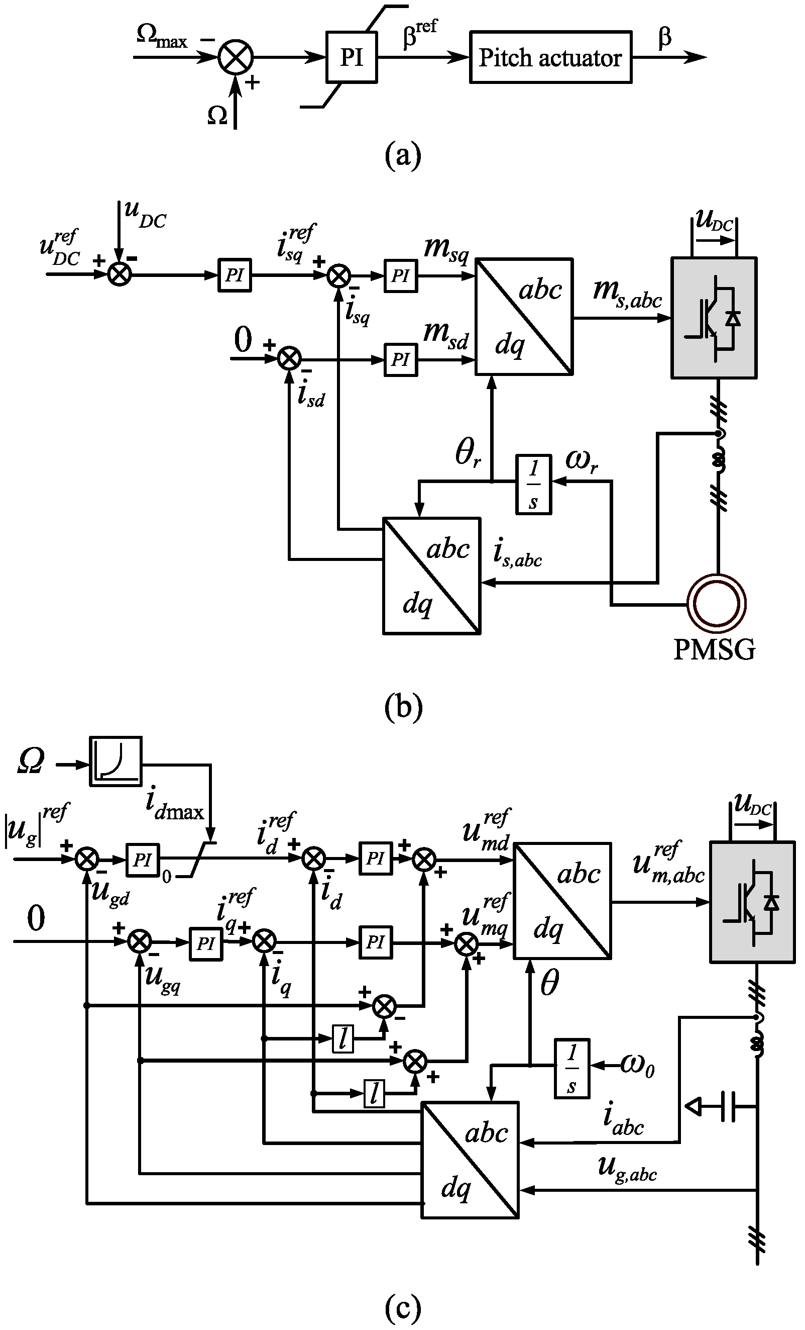
Therefore, power balance can be achieved by means of a speed control loop: only when the turbine power equals the load power is the rotational speed maintained constant. This speed control loop is shown in
Figure 4a.
The speed control loop will ensure that the maximum rotational speed of the WT is not exceeded by acting on the pitch control system. The blade pitch angle is adjusted, thus reducing or increasing the turbine power until it matches the load power. Note that this control system is similar to the one used in grid-connected WECS for limiting power when the wind velocity is higher than rated. The only difference is that here maximum rotational speed can be achieved at any wind velocity.
Moreover, instantaneous power variations will be supplied by the WT storage of kinetic energy since the pitch actuation is normally limited between 5°/s and 10°/s [
32].
3.2. Generator Side Converter Control
The GSC will be responsible for maintaining the DC-link voltage constant despite the WT speed and torque variations. This is achieved by the regulation of the active power drawn from the PMSG using the stator current q-component, which is related to active power as seen in Equation (
8). The control scheme is depicted in
Figure 4b.
On the other hand, there are several criteria for selecting the stator d-component current [
3]. In this paper, maximum torque per ampere (
) is employed.
This control loop is included in the VSC model of
Section 2.3 through the controlled current source
as
where
and
are the DC voltage controller proportional and integral gains, respectively. The dynamics of the internal current control loops are not considered since their bandwidth are one order of magnitude higher than the DC voltage control loop and thus they can be neglected in the VSC model.
is the DC voltage error state, given by
3.3. Voltage and Frequency Control
The VFC objective is to maintain constant voltage and frequency on the system. It is based on the orientation of the output voltage vector along a synchronous reference axis (d axis). The rotational speed of the synchronous reference axis is the reference frequency of the system . If the control can maintain the voltage vector orientated along the synchronous reference axis, the frequency is kept constant.
A linear approximation can be made between the magnitude and angle of the voltage and its d and q components, respectively. Considering that
where
is the angle between
and the d axis, the following can be deduced for small variations of
around 0:
Also, in steady state, if voltage and frequency are kept constant, then the LSC will supply the active and reactive power demanded by the load. Moreover, considering Equations (
17) and (
18), the control of magnitude (
) and angle (
) are related to the control of the active (
) and reactive (
) current, respectively, with a certain coupling between axes.
With such principles, the control system is quite simple. There are two control channels, the first one to obtain constant voltage, and the second one to obtain
(
Figure 4c) , which in turns means that the voltage vector is kept orientated to the reference axis.
The reference d-axis orientation is obtained by integration of the desired frequency . Note that a phase-locked loop (PLL) is not needed, because the whole control is oriented to a synchronous axis obtained directly from integration of the desired angular frequency and therefore the angular position is not subjected to any measurement noise or grid disturbance.
A dynamic saturation for
is also included. This saturation ensures that the WT never exceeds its stability limit as explained in
Section 2.1. When the available wind power is not enough to supply the load, the voltage magnitude will drop. In this case, balance must be achieved through load regulation or load shedding. Note that with the proposed VFC, the load shedding mechanism would be based on voltage deviation instead of classical frequency deviation. As stated in the introduction, this could be of application in systems where the load can be controlled such as battery chargers or electrical pumps.
To complete the state-space model described in
Section 2.3, the dynamics of the VFC are included. In the current controllers, the modulating signals
and
can be expressed as
where
and
are the current controller proportional and integral gains, respectively, and the compensating cross terms have been added.
and
are the d-q current error states, given by
Similarly, the voltage controller input is the voltage error, while the output is the current reference, given by
where
and
are the voltage controller proportional and integral gains, respectively, and the compensating cross terms have been added. As in the current controller,
and
are the d-q voltage error states, given by:
Considering the set of non-linear dynamic equations given in Equations (
17)–(
21), (
24), (
31), (
32), (
35) and (
36), the state-space representation of the system can be obtained through the Jacobian matrix as
where
and A, B, C and D contain only linear time-invariant coefficients.
4. Stability Analysis
In order to assess the dynamics and stability of the overall system, the eigenvalue and sensibility analysis are performed in the following paragraphs. For such purpose, the influence of the system parameters on the loci of dominant eigenvalues is studied considering the base-case scenario given in
Table 2.
Since the system is non-linear, the operation point, or quiescent point, also affects the stability of the system. The base-case operating point values are given in
Table 3.
For this base case, the eigenvalues are computed and presented in
Table 4. The frequency and damping ratio are also given, as well as the dominant states according to their participation factors [
33].
All the eigenvalues have a negative real part and thus the system is stable.
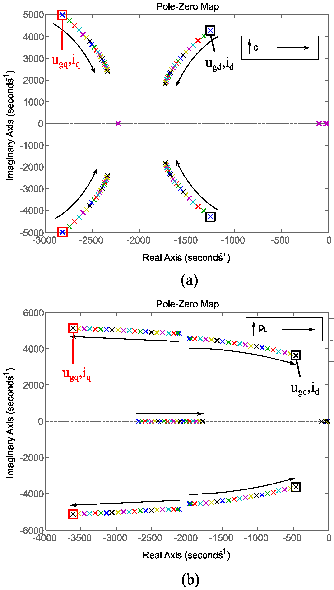
One of the system more relevant parameter is the total capacitance connected at the PCC.
Figure 5a shows the system eigenvalue map, together with the associated states, for a variation in
c from the base case of 0.1 to 0.3.
It can be concluded that a higher capacitance damps voltage variations and reduces the frequency of the associated eigenvalues. Consequently, a very small capacitance could compromise the system stability. Note that the proposed VFC is based on the regulation of the filter capacitance voltage, and thus it represents a relevant parameter for the proposed control system operation.
Due to the non-linearities of the load and the VSC models, the system is dependent on the active and reactive power demand.
Figure 5b shows the eigenvalues evolution for a variation of
from 0.1 to 1 p.u. It can be noted how the eigenvalues associated with
, and thus with voltage amplitude, move towards the imaginary axis. This means they tend to become more dominant and less damped. The opposite happens with the eigenvalues associated with
, and thus with voltage frequency.
This stability analysis shows the proposed system robustness against variations in both the operating point and internal parameters.
Variations of produce a similar effect but without influence on the eigenvalues related to DC voltage. Note that power variations could make the system unstable if the control gains are not selected correctly.
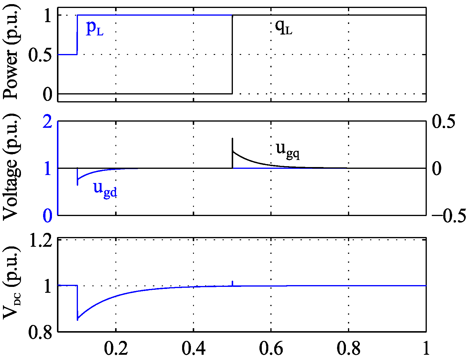
The complete model time-domain step response has been represented in
Figure 6. This figure shows the response to a 0.5 p.u. step in the demanded active power and to a 1 p.u. step in the demanded and reactive power. This figure demonstrates the capability of the proposed VFC to maintain constant voltage and frequency under such stiff changes. Also, it shows the active power mainly affects the voltage magnitude (d-voltage component) while reactive power mainly affects frequency (q-voltage component), because of the decoupled control strategy.
5. Results and Discussion
In this section, the detailed switching model simulations and real-time results are presented to demonstrate the capability of the proposed control operation as well as to validate the developed dynamic models.
These detailed simulations were developed using MATLAB/Simulink (R2013b, The MathWorks, Inc., Natick, MA, USA) in co-simulation with PSIM (version 9.0, Powersim, Inc., Rockville, MD, USA). Simulink was used to implement the control algorithms, whereas PSIM was used for simulating the power system elements.
Using this structure, the implementation of the models represented in
Figure 1,
Figure 2,
Figure 3 and
Figure 4 is fairly straightforward. The model has been discretized according to the simulation parameters given in
Table 5. Other parameters, such as control proportional and integral gains, are the same as in the base case presented in
Table 2 and
Table 3.
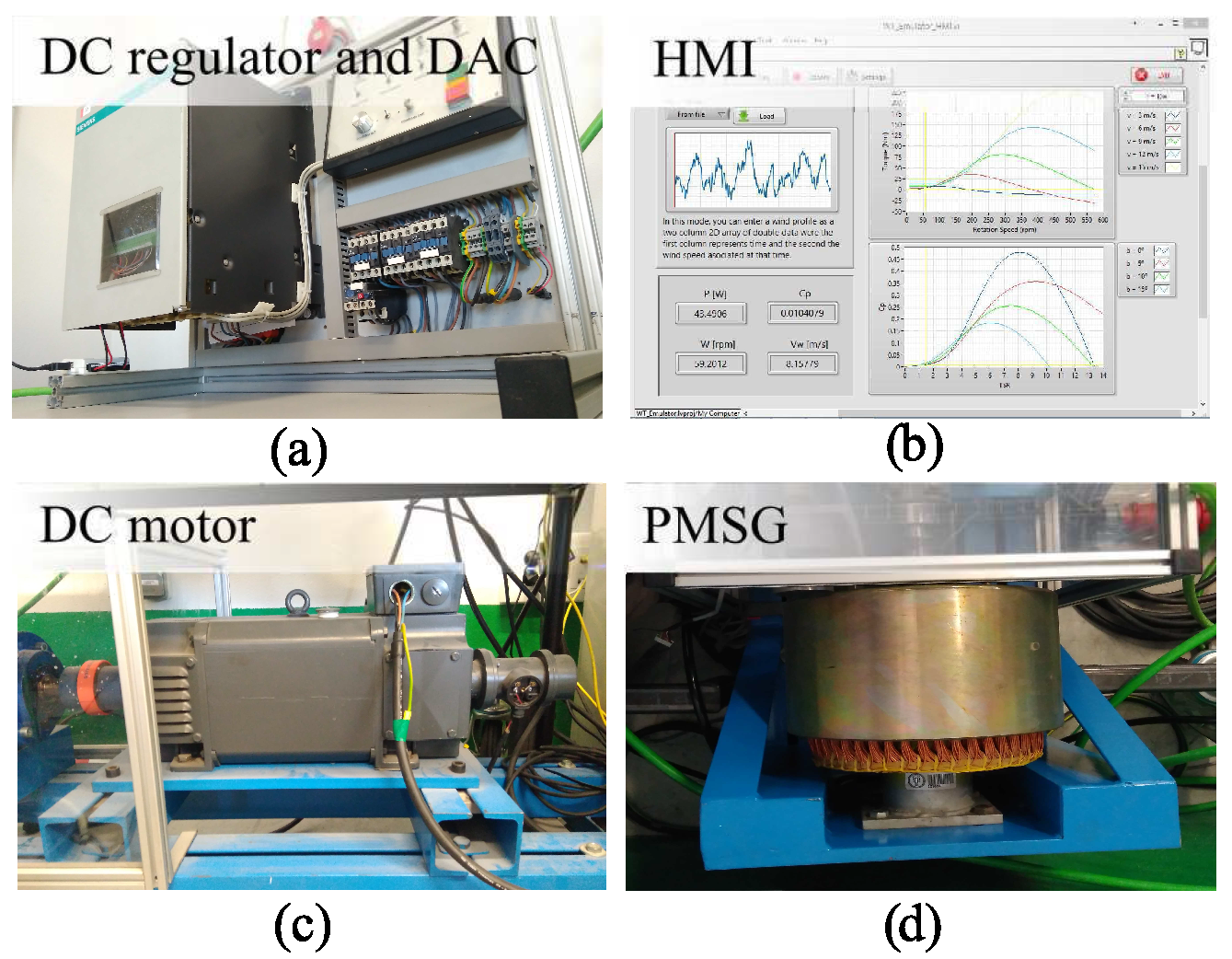
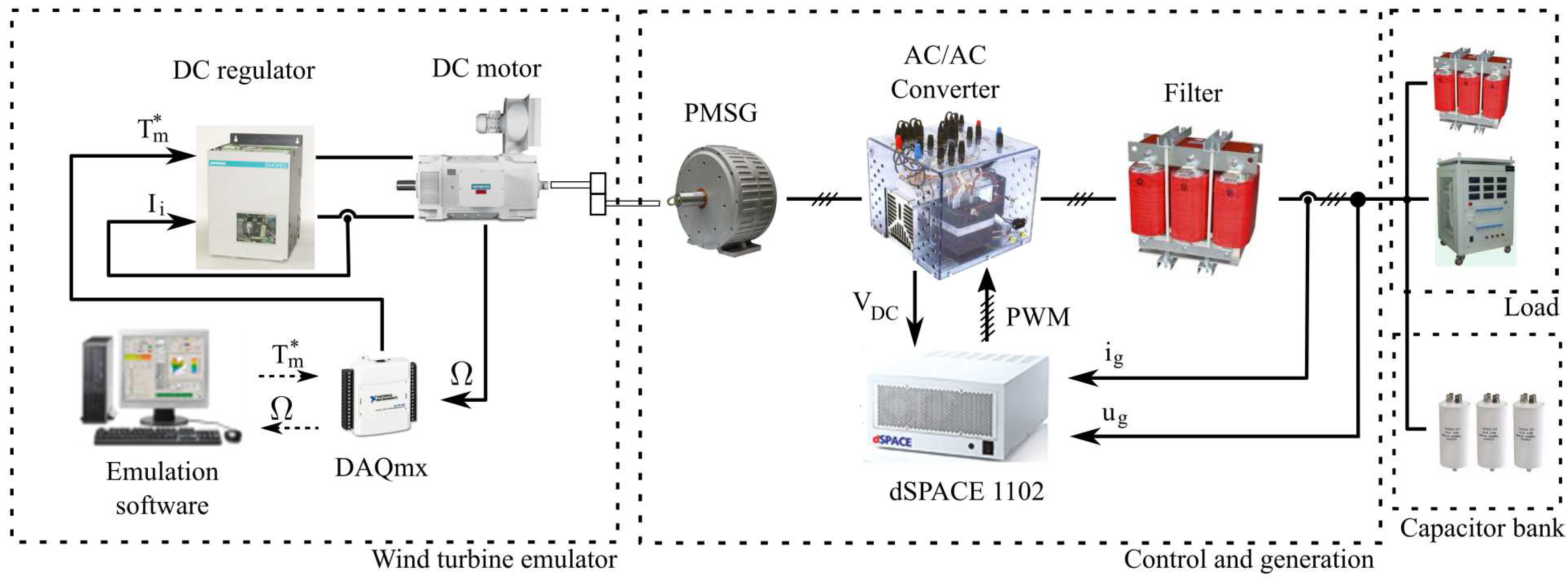
In order to obtain a further demonstration of the capabilities of the proposed control, the system was tested on the real-time test bench of
Figure 7. The WT was emulated based on the hardware-in-the-loop scheme developed in [
34]. A more detailed explanation is given in the
Appendix. The load could not be emulated as a constant power source, instead a resistor and a reactance were used.
Response to both wind and load variations was studied. In
Section 5.1 a load step at a constant wind speed is performed, and the effect on both the WT and the VSC is represented. In
Section 5.2, on the other hand, a variable wind speed is applied under constant load.
5.1. Load Step Response
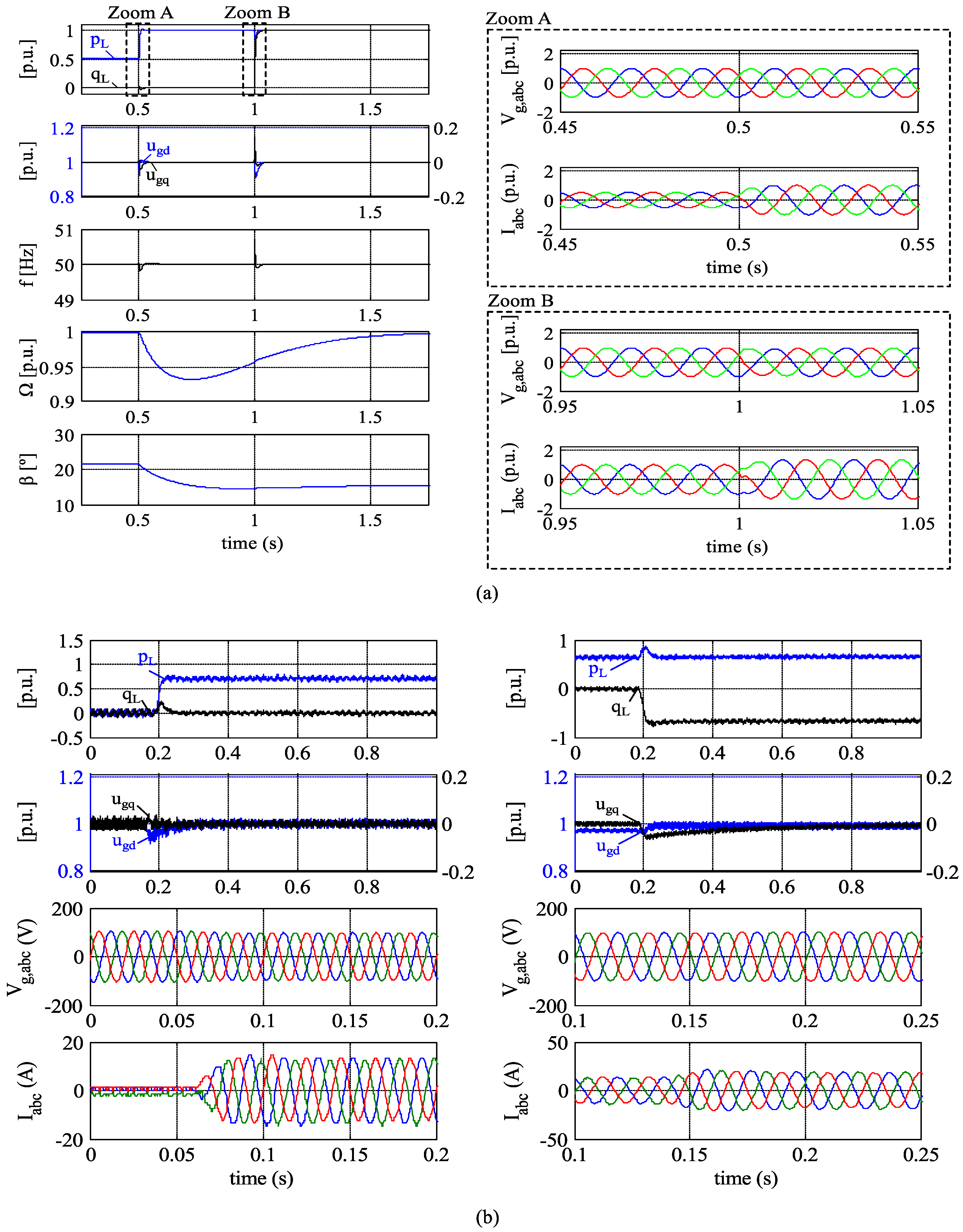
Despite load variations, the VSC control system must be able to maintain constant voltage and frequency. Also, the pitch control must ensure steady-state power balance between the WECS and the load to ensure a stable operation. Simulation results are shown in
Figure 8a and real-time results in
Figure 8b.
For the simulation, both active and reactive power variations are included. A 0.5 p.u. to 1 p.u. an active load step is applied at s, while a 0 p.u. to 1 p.u. reactive power step is applied at s. The dq components of the voltage only suffer small deviations at the changes, despite the load variation and therefore voltage and frequency are maintained constant after the transience. Frequency is influenced by both active and reactive power variations due to the coupling between axes. However, in contrast with most power systems, reactive power variations have a more significant influence. Zooms of the AC voltages and currents during load transitions are also included.
To obtain a stable operation, the power demanded by the load must equal the power extracted from the WT. For this purpose, the pitch angle must be decreased in order to increment power extraction. Note that pitch angle variations are considerably slower than the converter actuation. The difference between the load and WT power during this transience is drawn from the WT kinetic energy, producing a transience in the rotational speed, closing in this way the instantaneous power balance.
Reactive power demand is supplied by the VSC and thus has no influence on the WT power control.
Active and reactive power variations were also applied to the real-time system. It can be seen how these results validate the ones obtained in simulation and thus the same conclusions can be deduced.
5.2. Wind Variation Response
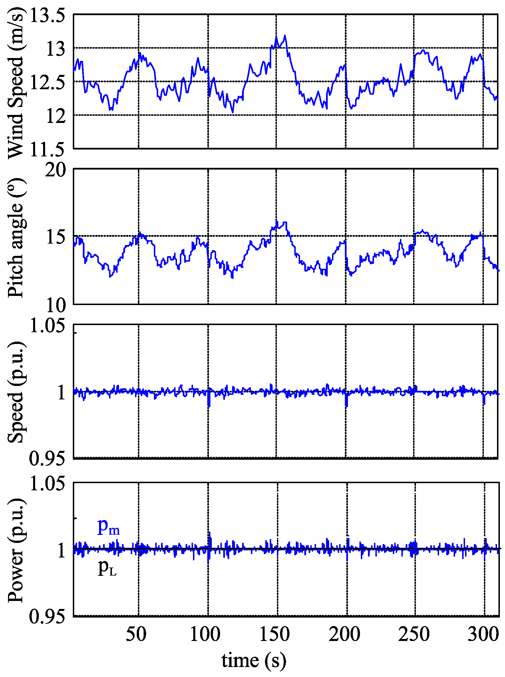
To study the system response to wind variations, the wind profile of
Figure 9 has been used. The profile consists of a turbulent variation around 12 m/s. Load is kept constant, so the WECS power must be constant despite the wind velocity variations. Only real-time results are shown to avoid a redundancy of information.
To balance the system, the objective of the pitch angle control is to maintain a constant WT speed.
Figure 9 shows that pitch angle follows wind velocity variations, increasing pitch angle if wind velocity increases or decreasing pitch angle if wind velocity decreases, in order to maintain constant rotational speed. Nevertheless, as the pitch actuator has a low bandwidth, there are some variations on the rotational speed and the WT power (
). This rotational speed variation precisely balances the WT power and output power of the WECS, as commented before.
6. Conclusions
This paper has presented the design and implementation of a VFC strategy for WECSs and its application for supplying an isolated load.
The decoupled control of the capacitor d-q voltage allows us to achieve a balance between demanded and generated active and reactive power, respectively, while maintaining constant voltage and frequency. Frequency control is achieved through the orientation of the voltage vector along an axis rotating at the reference frequency, avoiding the use of a PLL for frequency measurement.
The roles of the converters of the FC system are inverted. The WECS LSC controls AC voltage and frequency, while the GSC is responsible for maintaining constant voltage in the DC link. Therefore, power is fixed by the load demand instead of the WECS. Moreover, another contribution of the proposed control scheme is that the VFC uses an inner current control loop for controlling voltage, which allows for the regulation of the current and therefore avoids converter overload.
The use of the proposed VFC allows the LSC active power to precisely match the load demand. In contrast with other works, which focused on the integration of the WT with additional systems, in the presented work power balance is achieved by the speed regulation of the WT through pitch angle control and thus no additional power sources, dump resistors, or ESSs are required for the system operation.
Power balance is achieved by the speed regulation of the WT through pitch angle control and thus no additional power sources, dump resistors, or ESSs are required for the system operation.
Active power unbalance situations provoke voltage amplitude variations, instead of frequency variations as is the case in power systems with synchronous generators. Therefore, a load regulation or load shedding mechanism can be used to achieve power balance based on the voltage drop when wind power is not enough to supply the load. Nevertheless, once the power balance is restored, due to load regulation or wind speed rise, the algorithm operation is resumed automatically thanks to the included limitation, which avoids wind-up situations and dynamic instabilities.
The proposed control scheme has been completely modelled and validated by simulation and real-time implementation, demonstrating its capability to maintain constant voltage and frequency despite load and wind speed variations.

 ,
, 


