Abstract
Application of a pre-combustion chamber (PCC) ignition system is one of the methods to improve combustion stability and reduce toxic compounds emission, especially NOx. Using PCC allows the operation of the engine at lean combustion conditions or the utilization of low calorific gaseous fuels such as syngas or biogas. The paper presents the results of an experimental study of the combustion process in two stroke, large bore, stationary gas engine GMVH 12 equipped with two spark plugs (2-SP) and a PCC ignition system. The experimental research has been performed during the normal operation of the engine in an industrial compression station. It was observed that application of PCC provides less cycle-to-cycle combustion variation (more than 10%) and nitric oxide and carbon monoxide emissions decreased to 60% and 26% respectively. The total hydrocarbon (THC) emission rate is 25% higher for the engine equipped with PCC, which results in roughly two percent engine efficiency decrease. Another important criterion of engine retrofitting was the PCC location in the engine head. The experimental results show that improvement of engine operating parameters was recorded only for a configuration with one port offset by 45° from the axis of the main chamber. The study of the ignition delay angle and equivalence ratio in PCC did not demonstrate explicit influence on engine performance.
1. Introduction
Despite the introduction of modern low-emission high-speed four-stroke engines into the natural gas compression network, the share of old two-stroke type engines is still high. This is mainly because of their reliability, large base of qualified staff and significant number of such engines remaining from their wide dissemination in the past. The introduction of new regulations on the emission of toxic substances into the atmosphere, indicates the necessity to upgrade two-stroke engines of the older type in order to meet the limits. The high investment cost of purchasing new units results in the interest of two-stroke engine operators to upgrade their systems to comply with the new emission standards. The main contaminants emitted during the combustion of natural gas in these engines are nitrogen oxides (NOx) and unburned hydrocarbons. One of the most common of the old type natural gas units are two-stroke GMVH engines. Depending on the type of configuration, operating conditions and required power it can consist of 8, 12 and 16 cylinders depending on different power, adjusted to the size of the powered gas compressors. They are used in the transmission system of natural gas transported from Russia across Poland to the countries of Western Europe as well as the national gas transmission network. About 100 units work in this system at present [1]. These engines are usually operated for more than 8000 h a year. They are used to compress natural gas after the treatment processes (cleaning raw natural gas which can contain inert gases like nitrogen or carbon dioxide) as well as to drive the public gas transport system distribution. Nitrogen oxides released into the atmosphere negatively affect humans and other living organisms, causing damages or diseases of the nervous system and contributing to the formation of smog. The formation of nitrogen oxides in the combustion process is closely related to the parameters of the combustion process and the type of fuel burned [2]. Hence, three major mechanisms of their formation in flames have been considered: the fuel mechanism, the prompt mechanism, and the thermal mechanism [3]. For natural gas burned in pressure systems with a high ratio of the amount of energy extracted from the combustion chamber unit, the main mechanism responsible for the formation of NOx is the thermal mechanism [4]. Its intensity is closely related to the temperature of the combustion and the amount of oxygen in the reaction zone [5]. Higher combustion temperatures in the reaction zone result in higher NOx emissions [6].
New emission standards set a more restrictive emission limits like theDirective for Medium Combustion Plants (MCP) [7], where for a gas engine supplied by gases fuels (natural gas or non-standard gases) the NOx emission limit is 190 mg/m3 recalculated to oxygen content in exhaust gas equal to 15%. A vital role in fulfilling these environmental regulations is played by the application of the primary and secondary methods of toxic compounds reduction. In term of primary methods of NOx emission reduction, several approaches can be listed: creating internal or external exhaust gas recirculation, lean mixtures combustion (with high air excess ratio), modernization of ignition system burning of lean mixtures with high air excess ratio as well as modification of fuel and air supply system (high pressure of fuel injection).
Internal gas recirculation can be achieved by applying different valve lift profiles for the intake valves. Research provided by Königsson et al. [8] indicated that a 20% hydrocarbon emissions reduction can be obtained by increasing the swirl number from 0.4 to 3.0.
In case of external gas recirculation (EGR) Sorathia et al. [9] has proven that using this approach allows to decrease NOx emission by 45% for diesel engine when operating at full load for 15% of EGR. At the same level of EGR for GMVH-8 unit Rudkowski at al. [10] received 33% NOx reduction with decrease of overall engine efficiency by 2.75%. Moreover a 15% EGR rate allows effective reduction of NOx emission without significantly lowering the engine performance and emission [9].
The introduction of lean mixtures into the cylinder can reduce exhaust emission by lowering the combustion temperature, which prevents thermal nitrogen oxide formation and provides additional oxygen to oxidize unburned hydrocarbons and carbon monoxide. Ma et al. [11] investigated the spark ignition (SI) engine initially supplied with natural gas and its hydrogen blended mixtures influence on emissions and efficiency. For air equivalence ratio equal to 0.63 and with pure methane they achieved ten times the reduction of NOx (from 25 g/kWh to 2.5 g/kWh) compared to the case when equivalence ratio is equal to 1. The combustion of lean mixtures approach almost always involves the use of turbochargers. The use of lean air/fuel ratios is an important means of increasing engine efficiency and reducing exhaust emissions. The formation of nitrogen oxides (NOx) is primarily a function of temperature, so lower combustion temperatures resulting from lean combustion lead to reduced NOx emissions. Under lean operating conditions there is also an excess of oxygen available to oxidize carbon monoxide and unburned hydrocarbons. However, when the air-fuel ratio is directed toward the lean limit of combustion, misfire cycles occur and incomplete combustion results in rise of unburned hydrocarbons emission.
A different method of increasing the lean limit is charge stratification [12], meaning that the mixture in the region of the spark plug electrodes is richer than the surrounding ultra-lean air/fuel mixture.
Ma and Wang [13] investigated the extension of the lean combustion limit by introducing hydrogen to a natural gas spark-ignition engine. In the most favorable case with 50% hydrogen in supplied fuel they increased the lean combustion limit from ϕ = 0.59 (100% natural gas) to 0.42 [13]. Spark plug operation with ultra-lean air/fuel mixtures (ϕ > 0.57) and high pressures (>18 bars) is problematic from the ignition point of view. In such conditions, the classic spark plug lifespan tends to be very short. In modern applications, electrode erosion is reduced by maintaining fuel concentration in the spark gap and keeping the electrode within safe operating range as well as spreading the discharge energy per electrode unit surface area over a wider space [14].
Due to difficulties in ignition of lean mixtures using spark plugs, to facilitate this process, the ignition system is often equipped with pre-combustion chambers (called also prechamber) Prechambers are usually mounted to the cylinder head, in which combustion is initiated before charge enters into the main combustion chamber. The standard pre-chamber represents about one to two percent of the clearance volume. The ignition energy in this case is about one million times higher than in standard spark plug [15]. Most prechambers work on air fuel mixtures with an equivalence ratio more than 1. It results in higher nitrogen oxides formation in prechambers and therefore has a significant effect on the overall emission of nitrogen oxides. The emission of nitrogen oxides for ϕ = 1.25 was more than 70% higher than in case with ϕ = 0.95 (the drop from 155 ppm to 40 ppm referred to 15% oxygen in exhaust gases) [16]. In very lean combustion, the vast majority of nitrogen oxides are formed in prechamber. Burning of leaner mixtures in pre-combustion chamber (PCC) results in lower NOx emission but affects the stable operation. Tozzi et al. [17] investigated novel PCC technology with unique vortex flow providing reduction of NOx emission without compromising engine stability. They confirmed 34% reduction of NOx with a one percent gain in engine efficiency compared to 30% reduction of NOx with 7.5% loss of engine efficiency in classical PCC approach. In connection with the introduction of new emission standards in Switzerland [18], Roethlisberger and Favrat [19] successfully modernized the Liebherr G 926 TI engine powered by natural gas by using pre-chambers in place of spark plugs to reduce hydrocarbons (THC), carbon monoxide and nitrogen oxide emissions, achieving lower emission values than the new regulations. Application of prechamber autoignition potential in a lean combustion regime demonstrated negative impact on NO, THC and CO emission (increase by 202%, 45% and 30% respectively) with decrease of fuel conversion efficiency by 17% comparing to SI ignition system [20] Therefore, the use of self-ignition in the pre-chamber was not considered in this article.
The analysis of the GMVH-12 engine carried out by Rojewski [21] showed irregularity of pressures indicated in the cylinders. The modification of the fuel gas supply system in the form of swirling fuel valves was performed. After applying this solution, the pressure in the cylinders became more uniform, which positively influenced the engine efficiency.
A different approach for decreasing THC, CO and NOx emission in gas engines are the secondary methods. In case of NOx reduction selective catalytic or non-catalytic reduction (SCR, SNCR) can be applied. However, these solutions require additional equipment investments, reagent injection, more complicated measuring and control system, which results in a significant increase of operating expenses.
Considering the fact that the most favorable results were obtained with the use of precombustion chambers, it was decided to modernize the GMVH-12 engine using this technology.
The main objective of investigations presented in this article was to analyze and quantify the benefits of implementing the prechamber ignition system in a two-stroke, large bore reciprocating gas engine fueled by natural gas, especially by NO emission study. In first part of the study the engine GMVH-12 was equipped with classical spark plug (SP) ignition system while in the second stage of investigation the ECO-JET prechambers were installed. The parameters used to quantify the effect of various ignition systems on combustion process in gas engine the variance of peak pressure (COV) as well as the emission of nitric oxide (NO), carbon monoxide (CO) and total hydrocarbons (THC) were examined. In addition, the specific fuel consumption index gi was calculated for all performed engine tests.
2. Experimental Setup
2.1. Test Object
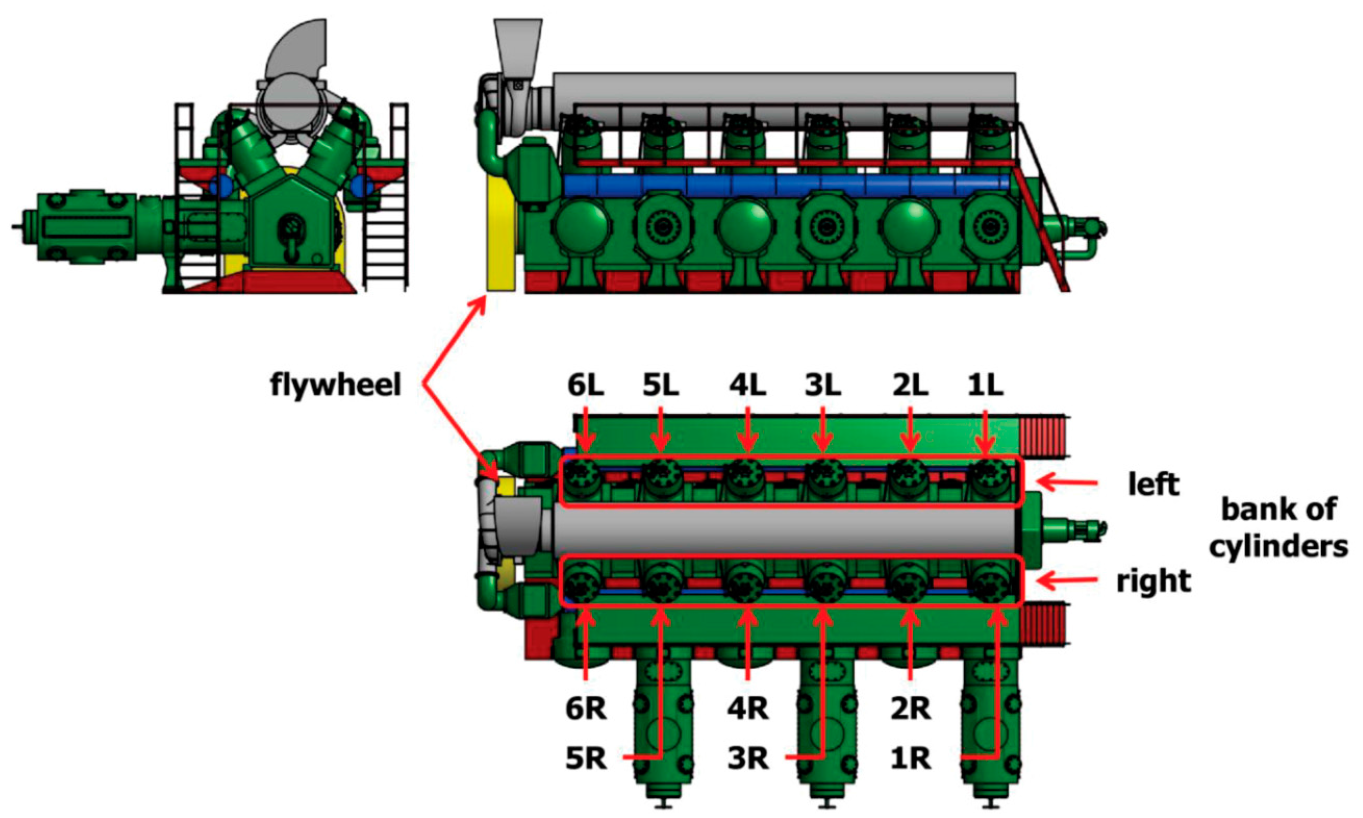
The investigated engine, type GMVH-12, is a twelve-cylinder, two-stroke gas engine driving three-cylinder gas compressors by common crankshaft system (Figure 1). The composition of the fuel is presented in Table 1.
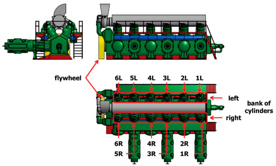
Figure 1.
Scheme of Cooper–Bessemer GMVH-12 engine [21].

Table 1.
Fuel gas composition.
The GMVH-12 engine is turbocharged with ET-18 turbochargers powered by exhaust gas coming from engine operation. It consists of a centrifugal blower and turbines mounted on a common shaft. The compression ratio of the turbocharger is 1:3. The GMVH-12 engine uses a transversely-flushed cylinder system. It consist of air injection into the cylinder at an angle to the cylinder head. Then the air stream turns and heads to the exhaust windows. Currently, the GMVH-12 engines are supplied with gas fuel by gas injection valves. They are located centrally in the cylinder head and their open–close drive is transmitted mechanically by cam followers from the cam placed on the connecting rod of the shaft. Pressure and the amount of gas supplied to the valves are controlled by the GOV 10/50 Gas Engine Governor based on engine load and engine rotational speed. The ignition is provided with two spark plugs located on the cylinder head. The main parameters of GMVH are presented in Table 2.
Table 2.
Basic parameters of gas engine.
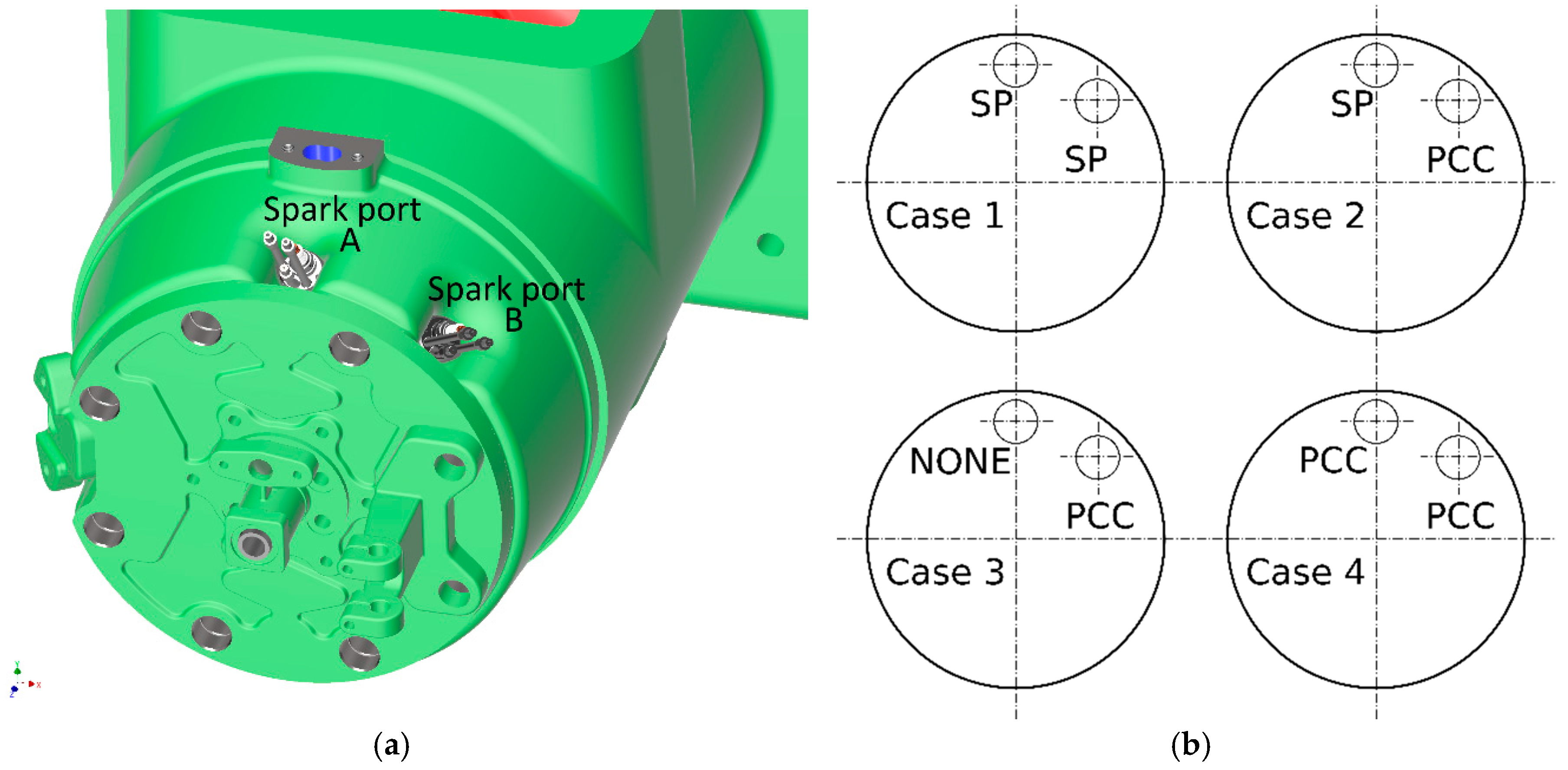
To study the influence of different ignition systems on combustion process in GMVH-12 engine, during the second stage of investigations the engine was equipped with scavenged ECO-JET prechamber. Accurate testing of these devices was carried out at Colorado State University [15,16]. The cross-sectional view of ECO-JET prechamber is displayed in Figure 2. The volume of PCC used in the current work is 38.9 cm3, which corresponds to 1.35% of the clearance volume. Initially the GMVH-12 engine was not designed for operation with a PCC ignition system. Therefore, systems are pre-assembled in place of one of the two spark plugs located in the cylinder head. These openings are positioned at an angle (Figure 3) so the gas emerging from the prechamber through the single hole is able to spread in a considerable volume of the main chamber.
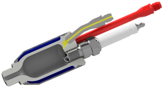
Figure 2.
Cross section of ECO-JET prechamber.
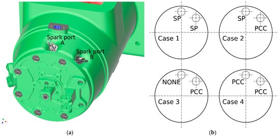
Figure 3.
(a) Location of spark plug (SP) or pre-combustion chamber (PCC) in cylinder head; (b) Configurations of investigated ignition system.
The ECO-JET prechambers are equipped with a water jacket cooling system which is connected to the external water supply system. Thanks to this solution it was possible to use standard cylinder heads which initially do not allow cooling of the prechamber.
2.2. Experimental Procedure
The study of the ignition system type influence on combustion process in large bore, stationary gas engines were divided into three parts. The purpose of the first stage was to analyze the operation of the GMVH-12 engine equipped with a classic (two spark plugs per cylinder) ignition system. Parameters characterizing engine operation, like peak pressure in cylinder, indicated mean effective pressure (IMEP) [22], specific fuel consumption and emission of toxic compounds (NO, CO, THC) were investigated. The tests were done for five rotational speeds from 290 up to 330 rpm with an accuracy of ±2 rpm. The indication process of each cylinder was prepared using measuring device Ultima EDI equipped with Kistler piezoelectric combustion sensors with the total accuracy of 1.5%. The flue gas composition was measured using a set of gas analyzers (Emerson Rosemount) with the following sensors: infrared (CO, CO2), chemiluminescence (NO), paramagnetic (O2) and the Flame Ionization Detector (THC). Accuracy of gas analyzers is presented in Table 3.
Table 3.
Basic parameters of gas engine. THC: Total hydrocarbon.
In the second step of study, a separate single cylinder was analyzed. Several different configurations of the ignition system were tested. In Case 1 two spark plugs were used, in Case 2 one SP and one PCC, while in Case 3 only one PCC. In Case 4 two PCC were installed instead of spark plugs. During the investigation of one PCC (Case 3) the prechamber was installed in two different places in the cylinder head located in the ports A and B (as presented in Figure 3). In addition, in Case 3 and Case 4 the influence of ignition time and different stoichiometry in PCC were tested. The ignition time has been changed by decreasing the ignition angle to −2° before the top dead centre (TDC). For other tests, the ignition angle was set on −5.4° by engine automatic control system. Further, the stoichiometry in PCC was changed by supplying additional air to ECO-JET prechamber. The compressed air before the pre-chamber inlet was mixed with fuel and as a premix mixture injected into the engine cylinder. The amount of air supplied to the prechamber during normal operation is the result of the pressure exerted by the movement of the piston and diameter of the PCC outlet opening. Therefore, it is impossible to characterize the value of equivalence air ratio. The third part of the investigation has been prepared for gas engines equipped with one pre-combustion chamber per one cylinder mounted in port A (Figure 3). During this stage of investigation the same parameters characterizing engine operation as in the first step were collected for five engine rotational speeds. Obtained data was used for analysis of the influence of prechamber installation on operation parameters of engine.
3. Results and Discussion
3.1. Preliminary Test with Two Spark Plugs Ignition
In the first stage of study each cylinder of GMVH-12 gas engine was equipped with two spark plugs, where the ignition delay was controlled automatically and set on an angle equal to −5.4° before the TDC. Main working parameters of engine are presented in Table 4. The analysis of mean effective pressure distribution and overall emission have been collected for five rotational speeds (range from 290 up to 330 rpm). In addition, the specific fuel consumption parameter was calculated according to Formula (1), where the Qb is the fuel gas consumption presented in m3/h and Ni is average power value of the engine calculated based on the indicated pressure of 12 cylinders in [kW]. Specific fuel consumption for the two spark plugs configuration ranged from 0.274 Nm3/kWh to 0.269 Nm3/kWh for 290 and 330 rpm respectively.
Table 4.
Work parameters of GMVH-12 engine.
The example of combustion pressure distribution trends for 12 cylinders at 300 rpm rotational speed is demonstrated in Figure 4. For all tests, the coefficient of variation for engine before modifications COVE,I was calculated as the ratio of standard deviation of the main chamber peak pressures and the average main chamber peak pressure from 12 cylinders [23]. Main chamber peak pressure was designated on 10 work cycles from one engine cylinder. For each cylinder, a series of IMEP measurements were performed. Figure 4 displays indicated mean effective pressure for 12 cylinder of GMVH-12 engine.
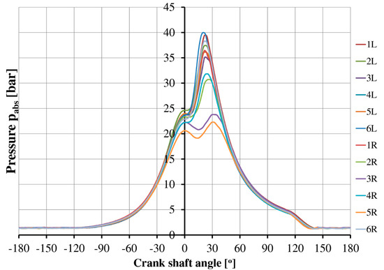
Figure 4.
Indicated mean effective pressure for 12 cylinders of the GMVH-12 engine, rotational speed 300 rpm, spark plug ignition system.
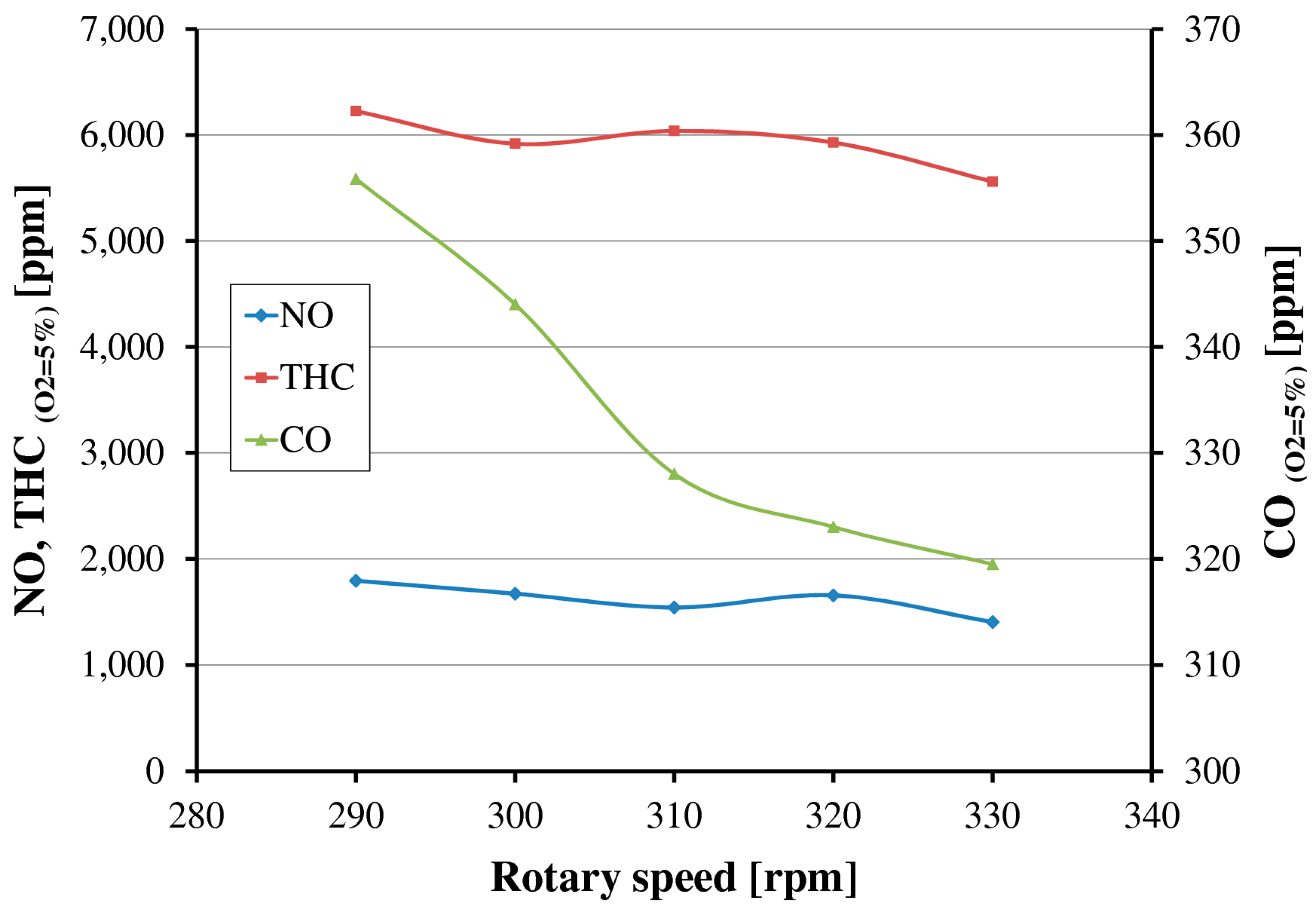
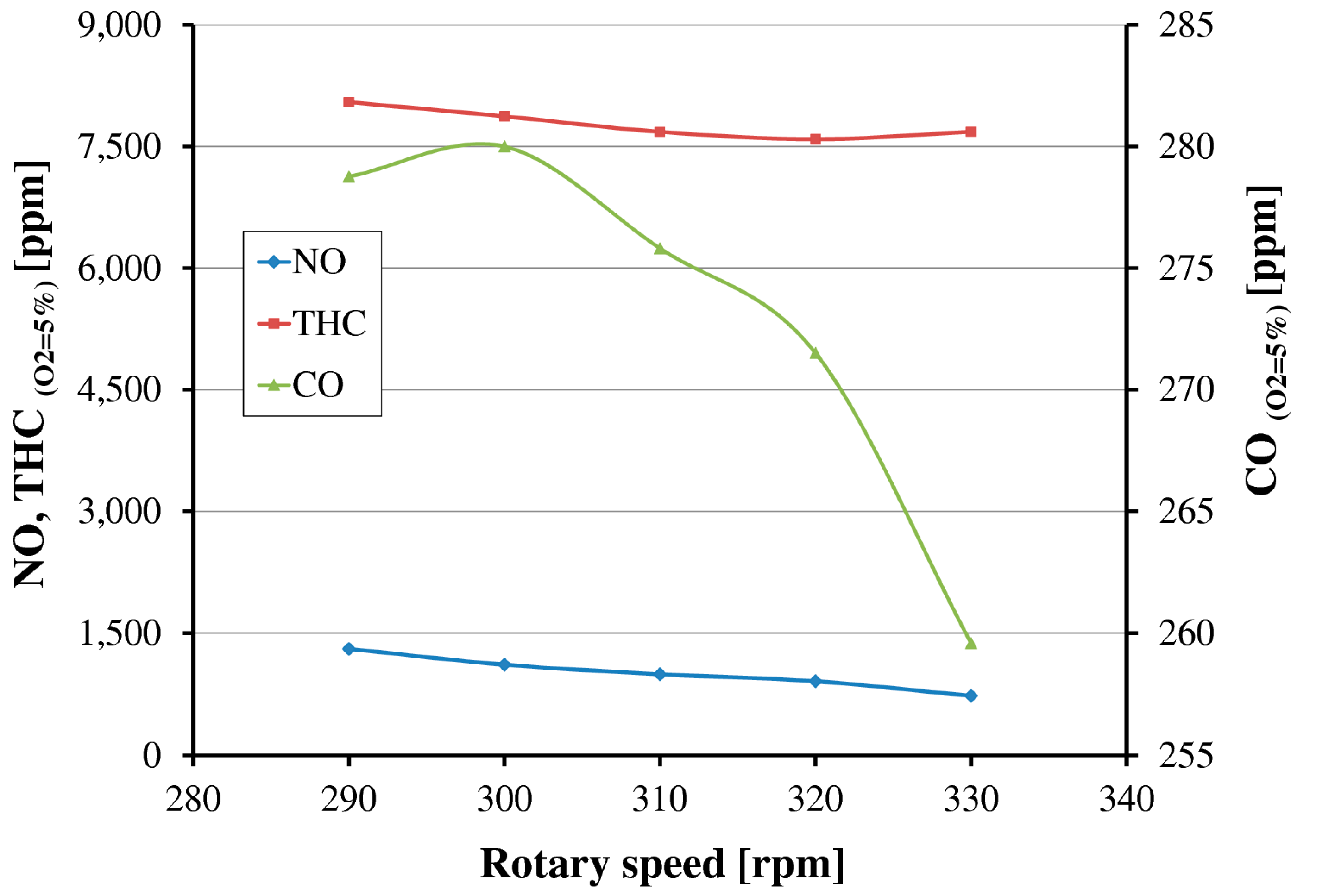
The obtained COVE,I covers the range from 10.9 up to 13.4. The lowest value was measured for 300 rpm and maximum value at 320 rpm. It shows high combustion instabilities caused mainly by misfiring. Second group of analyzed parameters was overall emission of NO, CO and THC toxic compounds from the whole engine. The results are presented in Figure 5.
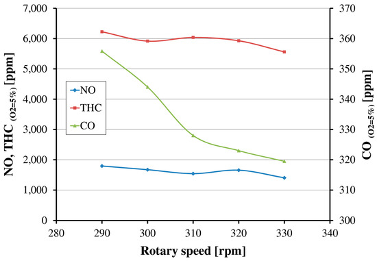
Figure 5.
Overall emission for gas engine GMVH-12 with spark plugs ignition system.
It can be observed that the values of all measured compounds decrease with an increase in the rotational speed. Nitric oxide emission is about 30% lower than presented by Rudkowski et al. [10] for two stroke gas engine GMVH-8 with EGR, but still four to five times higher than emission limits for new engines [7]. The gas analyzers for THC were calibrated using a mixture of CH4 and N2 as span gas, thus the displayed results for high hydrocarbons emission refer to molar fraction of methane in flue gases. The maximum value of THC (0.82%) was obtained for the rotational speed equal to 290 rpm which is about 7.8% of the total amount of fuel delivered to the engine. For other speeds, the average value was also on high level equal to 7.4%.
The analysis of literature and experience of industrial practice has identified that there is a possibility to achieve improvement in emission of toxic compounds emission reduction by modernization of the engine. The modification of ignition system with use of precombustion chambers was selected.
3.2. Study of One Cylinder Work
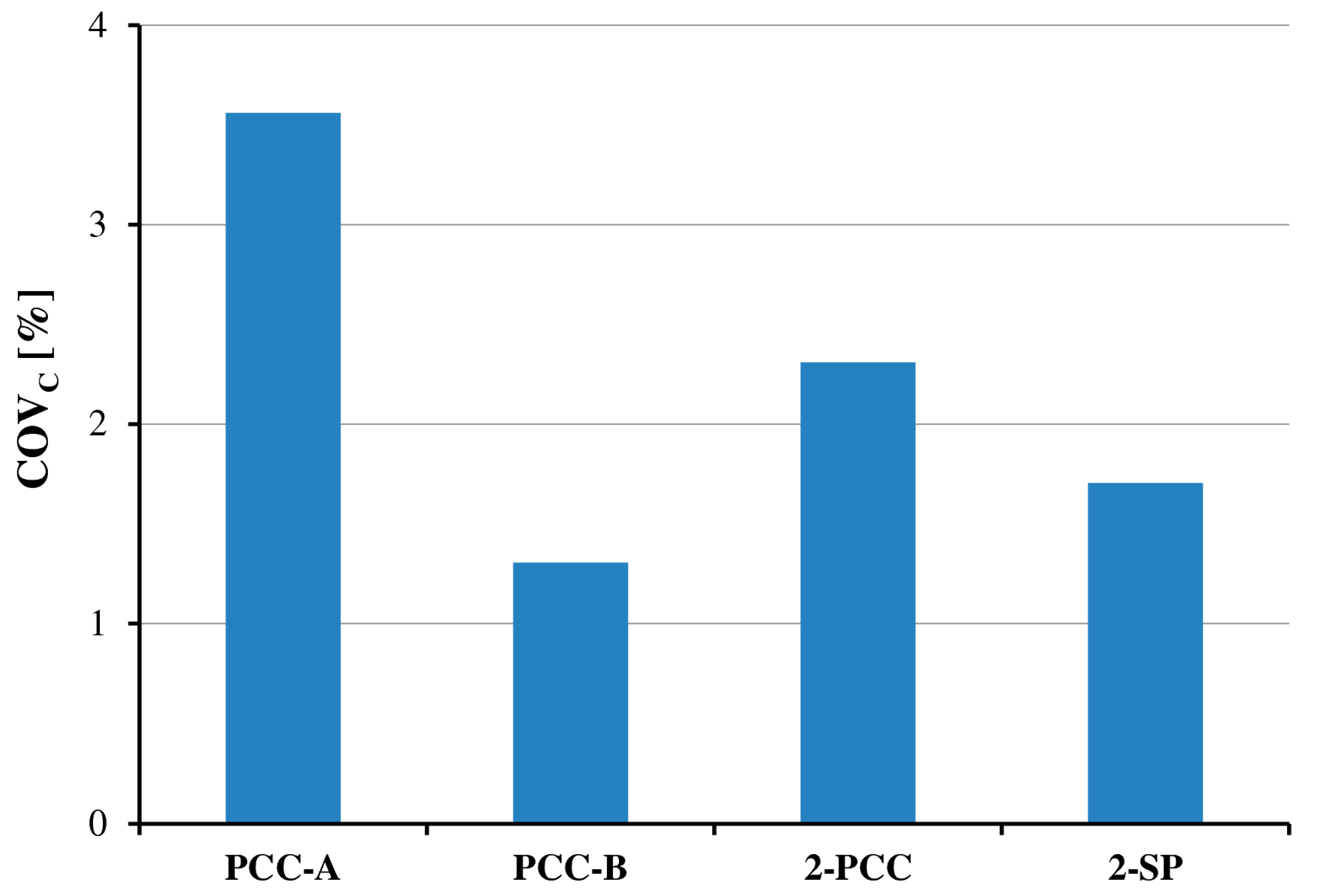
To determine the best arrangement of the ignition system, one randomly selected cylinder was investigated in the second stage of study. In the preliminary tests, the cylinder was equipped with two spark plugs, while in the further attempts the prechambers were used. The investigation has been done at one rotational speed of 320 rpm for three configurations of ignition system with PCC. Initially GMVH-12 engine is equipped with two spark plugs. Therefore, it was possible to study the influence of PCC location in the cylinder head, in place of spark plugs ports on the combustion stability as well as emission of THC, NO and CO. For all performed tests coefficient of variation from one cylinder for different configurations of ignition system COVC was calculated. The COVC is the ratio of standard deviation of main chamber peak pressures and average main chamber peak pressure from 10 work cycles of one cylinder. The results of determined COVC are presented in Figure 6.

Figure 6.
Variance of peak pressure COVC for different ignition systems.
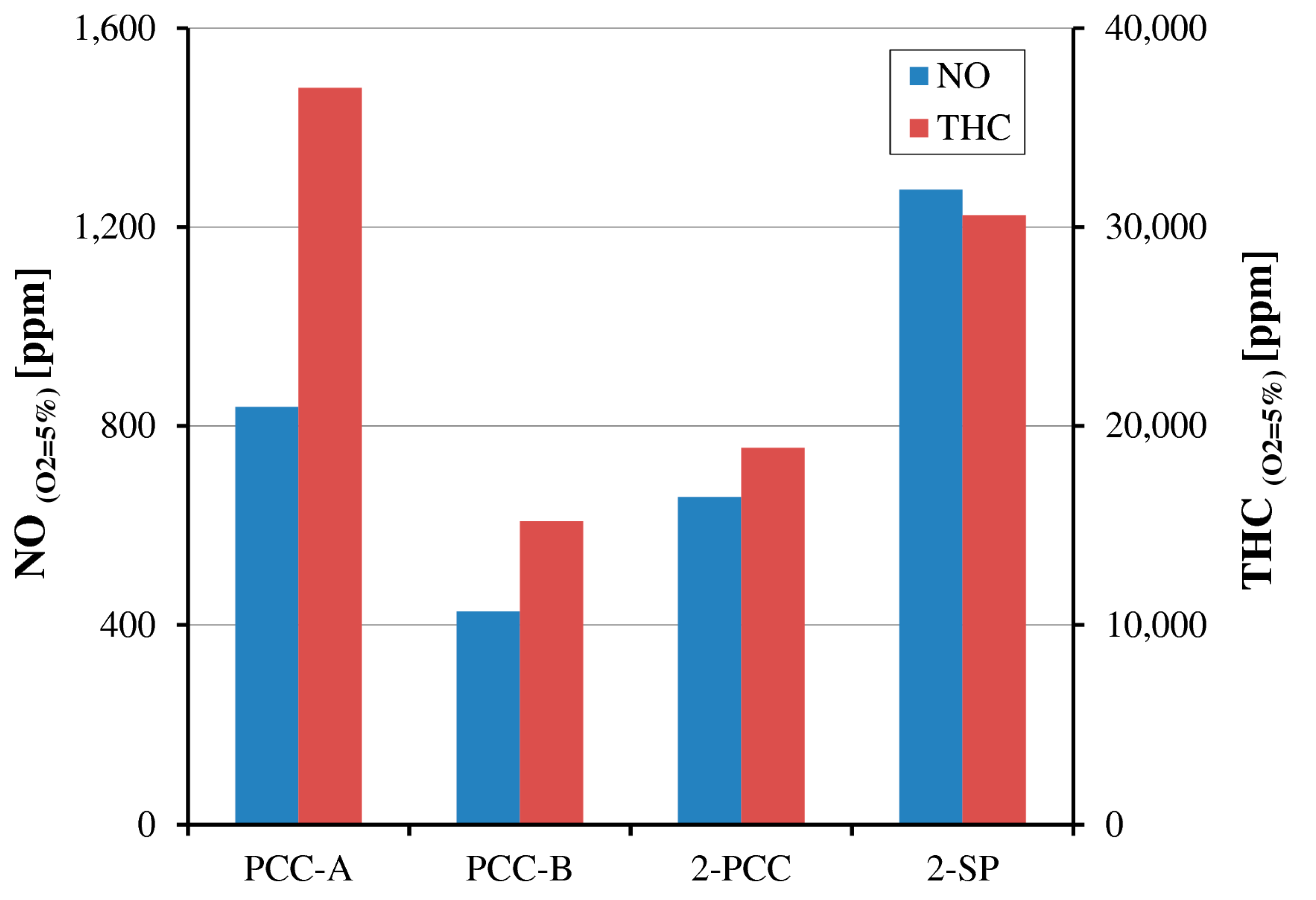
It can be noted that the most uniform combustion process inside the cylinder (the most uniform distribution of combustion pressure) was obtained for case with only one PCC in port B. The value of COVC is 1.4%, which is 20% lower than for two spark ignition configuration. The obtained values can be referred to results of Olsen and Lisowski investigations on single separated cylinder, where the COV has ranged from 10% to 25% depending on equivalence ratio in the prechamber [16]. For prechamber installed in port A the combustion instabilities increase. This phenomena could be explained by air-fuel mixture composition distribution in the cylinder, as near to the port A the stoichiometric composition is present. This conclusion is based on Computional Fluid Dynamics (CFD) calculation results of natural gas combustion process in GMVH-12 engine. It can also explain that more stable combustion, in comparison to 2-PCC case, occurs in 2-SP configuration, (COVC = 2.3 and 1.7 respectively for 2-PCC and 2-SP). Delivering of additional air to the PCC-B, results in increase intensity of misfiring (mixture is out of high flammability limits) and unburned fuel is injected to the main cylinder which influences the dose composition. The ignition occurs only for one PCC-A but not all fuel is burned. This hypothesis can be confirmed by analyzing the THC emission, as its value for PCC-A is higher than for test with only one PCC located in port B. The results of influence of ignition system on emission of toxic compounds for one cylinder are displayed in Figure 7.

Figure 7.
Emission of NO and THC for different ignition systems from one cylinder of GMVH-12.
For all investigated tests when using PCC (PCC-A, PCC-B, 2-PCC), NO emission was lower than in two spark plugs basic configuration. It is the result of spatial distribution of the combustible mixture ignition by flame jet exiting from the PCC, as its energy is in the order of one million times the spark plug discharges [15]. Therefore, it allows to ignite leaner mixtures, reduce the peak of combustion temperature and consequently reduce the NO formation through the thermal mechanism. For PCC-B and 2-PCC configurations the reduction of THC was also observed (compared to 2-SP ignition). It is likely caused by the combustion stability. In the case with PCC-A, where the combustion mixture is too rich for proper ignition, the increase of THC is significant compared to PCC-B test results, and even for 2-SP ignition configuration. Based on the analysis of the results shown in Figure 6 and Figure 7 it can be concluded that the best ignition system solution for the investigated engine will be one pre-combustion chamber located in port B. For this case the lowest emission of NO, more consistent combustion and less cycle-to-cycle combustion variation is obtained, which leads to the lowest THC emission.
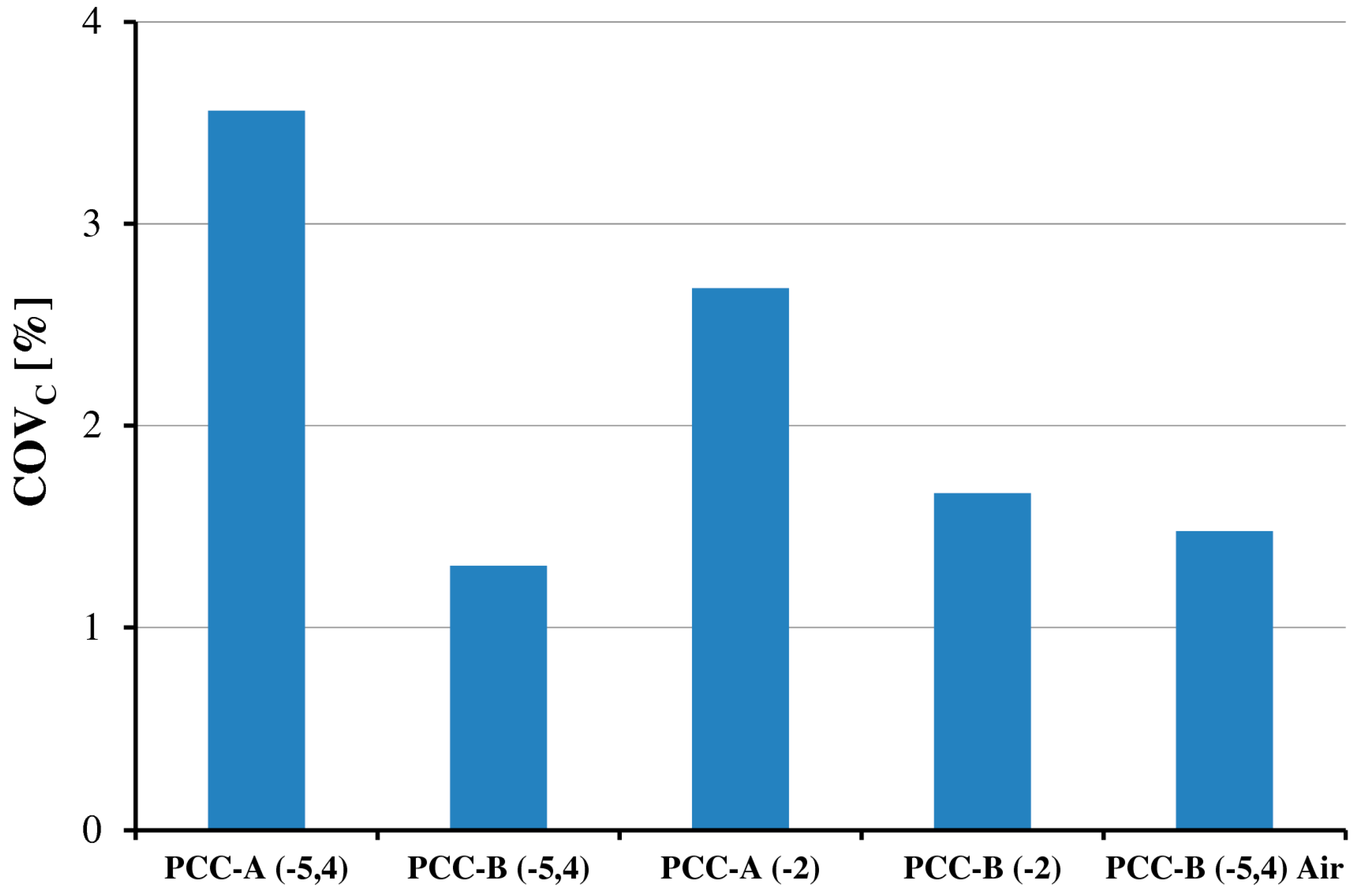
In the next step of single cylinder operation study, the influence of ignition time and different stoichiometry in PCC was tested, but only for two configurations of ignition system: the pre-combustion chamber located in port A or port B. The ignition delay was decreased to −2° before TDC of the piston. This solution favorably affects the reduction of nitric oxides formation (NO decreasing—in case of 2-SP ignition) but also reduce the value of IMEP and consequently decreases the engine efficiency. The results of ignition delay influence on emission and combustion stability are presented in Figure 8.
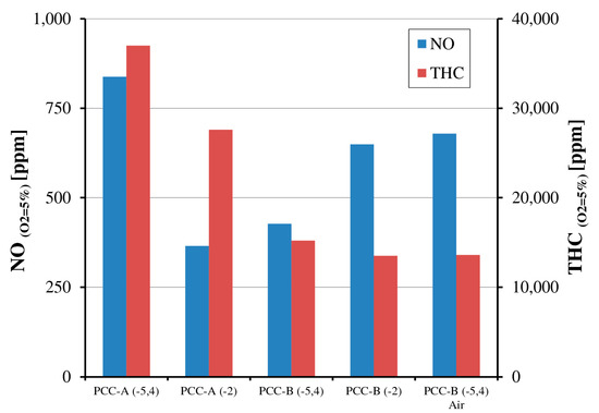
Figure 8.
Emission of toxic compounds versus ignition time.
Results presented in Figure 8 show that nitric oxide reduction is observed only for the PCC-A case, and is about 60% when ignition delay is shifted to an angle of −2° before TDC. For PCC located in port B, the NO increases by 75%. Similar trend is observed for combustion stability, improvement for PCC-A and deterioration for PCC-B. Decreasing of combustion stability for pre-combustion chamber located in port B does not affect the THC emission, because overall emission decreases for both investigated cases, when the ignition occurs later. Further analysis of Figure 9 shows that combustion stability is worse, when additional air is delivered to the prechamber. The value of variance of peak pressure coefficient increases from 1.3% up to 1.5%. Additionally, decreasing of equivalence ratio in PCC causes significant increase of NO emission and slight reduction of THC amount in the exhaust gases. As mentioned earlier, during the experiment it was impossible to characterize the air–fuel ratio equivalence value in PCC. Therefore, in the final step of research the pre-combustion chamber without supply of additional air was used and future investigation are needed.
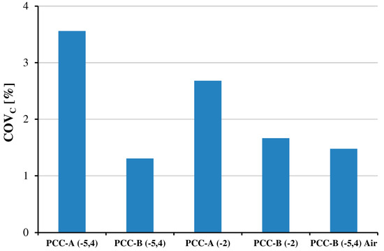
Figure 9.
Combustion stability (COVC) versus ignition time.
3.3. Analysis of Engine Operation with PCC Ignition System
During the last step of the investigation, the engine was equipped with an ignition system based on one pre-combustion chamber located in Port B in each of twelve cylinders. The selection of configuration was done based on results of one cylinder work in which the lowest NO and THC emission as well as the lowest value of COV were observed. The angle of ignition was set at −5.4° before TDC. Experiment has been prepared for five rotational speeds from 290 to 330 rpm. During the investigation, the analysis of main engine operating parameters was performed. The value of peak pressure coefficient variance COVE,II was calculated as a ratio of standard deviation of the 12 cylinders peak pressure and average IMEP of the engine after modification.
Figure 10 shows the overall emission of toxic compounds for the whole engine equipped with a pre-combustion chamber. It can be observed that contents of nitric oxide and carbon monoxide significantly decrease, while the THC share rises, compared to engine equipped with 2-SP. Reduction of NO emission has changed from 33% at 290 rpm up to 60% at 330 rpm. Reduction of nitric oxide is due to the lack of high temperature peak region in the main combustion chamber, induced by the spark plug ignition. Additionally the pulse jet injected from PCC causes the entrainment and mixing of fresh charge in the main combustion chamber and ensures more uniform distribution of air-fuel mixture, reducing areas of enriched mixture inducing increased NO formation.
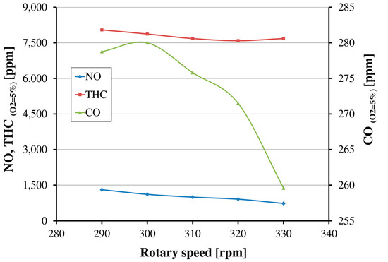
Figure 10.
Overall emission for gas engine GMVH-12 with pre-combustion chamber ignition system.
The emission of THC rose by around 25% for all examined rotational speeds and causes the increase of the specific fuel consumption value parameter to 0.291 Nm3/kWh. In comparison to tests with 2-SP ignition configuration, the gi increased by around seven percent, which means a roughly 2.2% reduction of fuel conversion efficiency. Similar results were obtained by Roethlisberger and Favrat [24], where the comparison of operating parameters of natural gas powered engine equipped with prechambers and spark plugs was realized. Increase of THC emission can suggest the drop of combustion stability. Although the calculated values of COVE,II coefficient decreased for all investigated rotational speeds. The value of COVE,II is in the range from 9.9 up to 12.4 with an average value of 10.8 (11.7 for engine with 2-SP). This means that PCC ignition system improves combustion stability by eight percent compared to 2-SP system. In Figure 11, a comparison of maximum peak of pressure for the whole engine with two investigated ignition systems is presented.
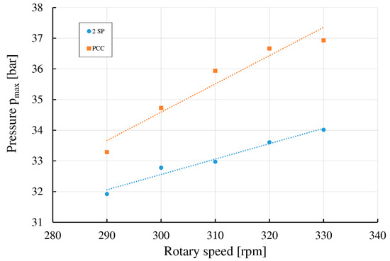
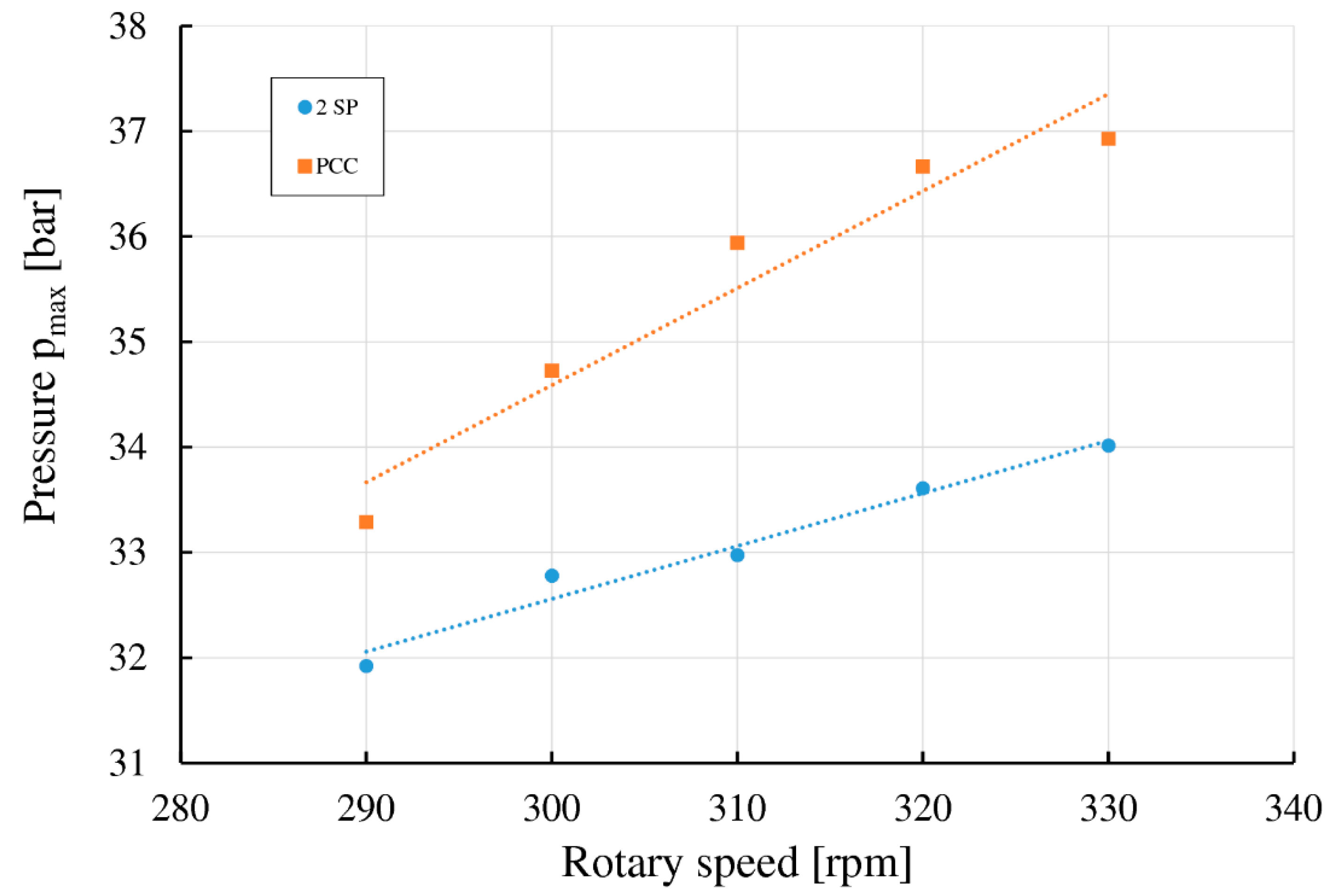
Figure 11.
Peak of pressure for GMVH-12 engine with SP and PCC ignition arrangements.
The explanation of increased THC emission can be that the back parts of prechamber and near piston wall regions are the place of unburned methane formation and increased emission. The temperature rise is repressed due to heat transfer to the cylinder walls causing incomplete combustion. Lean mixtures sitting beyond the flammability limits disrupt flame propagation and part of the mixture remains without burning, resulting in increased hydrocarbon emission [25].
4. Conclusions
The current investigation on influence of ignition system in a two stroke, large bore stationary gas engine has shown that adding a prechamber ignition system provides better combustion stability and decreases toxic compounds emission such as nitric oxide and carbon monoxide compared to a spark plug arrangement. For both configurations the overall emission decreases with the rise of engine load.
The retrofitting of investigated engine by change of ignition system led to several positive phenomena such as:
- ▪
- decrease of nitric oxide emission up to 60%;
- ▪
- reduction of carbon monoxide in the range from 22–26%, for 290 and 330 rpm respectively;
- ▪
- improvement of combustion stability by eight percent compared to 2-SP system;
- ▪
- increase of maximum peak pressure value.
Experimental study of separate cylinder work has shown that the location of the prechamber in the cylinder head has a significant influence on the engine operational parameters. During the study, two ports were investigated, one located in the axis of the cylinder (port A) and the second one in port B. Combustion stability improvement (lower value of COVC) as well as NO and CO content reduction were observed only for port B, while for port A the overall emission was similar to emission for 2-SP ignition but more engine misfire was measured (COVC = 3.6). Further analysis including the influence of ignition time and stoichiometry in PCC allows us to make the following observations:
- ▪
- ignition time delay improves the combustion stability and reduces the NO and THC emission in case of PCC-A, while for PCC-B this trend is the opposite;
- ▪
- nitric oxide emission and combustion instability increase with the decrease of equivalence ratio.
The results confirm that the pre-combustion ignition system can be successfully used as an upgrade for a two-stroke gas engine equipped with a spark plug ignition. It ensures reduction of combustion instability and toxic compounds emissions with a slight decrease in efficiency.
Author Contributions
Rafał Ślefarski and Jacek Wawrzyniak conceived and designed the experiments; Michał Gołębiewski, Paweł Czyżewski, Jacek Wawrzyniak, Rafał Ślefarski and Przemysław Grzymisławski performed the experiments; Michał Gołębiewski, Rafał Ślefarski, Paweł Czyżewski and Przemysław Grzymisławski analyzed the data; Rafał Ślefarski and Jacek Wawrzyniak contributed reagents/materials/analysis tools; Paweł Czyżewski, Rafał Ślefarski and Michał Gołębiewski wrote the paper.
Conflicts of Interest
The authors declare no conflicts of interest.
Nomenclature
| IMEP | indicative mean effective pressure |
| COV | coefficient of variation |
| TDC | top dead center |
| PCC | precombustion chamber |
| 2-PCC | two precombustion chamber |
| PCC-A | precombustion chamber located in port A |
| PCC-B | precombustion chamber located in port B |
| SP | spark plug |
| 2-SP | two spark plugs |
| THC | total hydrocarbons |
| EGR | external gas recirculation |
| SCR | selective catalytic reduction |
| SNCR | selective non catalytic reduction |
| C | cylinder |
| E,I | engine with spark plugs ignition system |
| E,II | engine with prechamber ignition system |
| gi | specific fuel consumption |
| ϕ | equivalence ratio |
| rpm | revolutions per minute |
References
- Rojewski, J.; Ślefarski, R.; Wawrzyniak, J. Analysis of combustion process in industrial gas engines powered with high methane and nitrified low-calorific gases. Siln. Spalinowe 2013, 52, 42–50. [Google Scholar]
- Bhandari, K.; Bansal, A.; Shukla, A.; Khare, M. Performance and emissions of natural gas fueled internal combustion engine: A review. J. Sci. Ind. Res. 2005, 64, 333–338. [Google Scholar]
- Hill, S.C.; Smoot, L.D. Modeling of nitrogen oxides formation and destruction in combustion systems. Prog. Energy Combust. Sci. 2000, 26, 417–458. [Google Scholar] [CrossRef]
- Knop, V.; Benkenida, A.; Jay, S.; Colin, O. Modelling of combustion and nitrogen oxide formation in hydrogen-fuelled internal combustion engines within a 3D CFD code. Int. J. Hydrogen Energy 2008, 33, 5083–5097. [Google Scholar] [CrossRef]
- Raine, R.R.; Stone, C.R.; Gould, J. Modeling of nitric oxide formation in spark ignition engines with a multizone burned gas. Combust. Flame 1995, 102, 241–255. [Google Scholar] [CrossRef]
- Krishnan, S.R.; Srinivasan, K.K.; Singh, S.; Bell, S.R.; Midkiff, K.C.; Gong, W.; Fiveland, S.B.; Willi, M. Strategies for Reduced NOx Emissions in Pilot-Ignited Natural Gas Engines. J. Eng. Gas Turbines Power 2004, 126, 665–671. [Google Scholar] [CrossRef]
- European Union. Directive (EU) 2015/2193 of the European Parliament and of the Council—Of 25 November 2015—On the Limitation of Emissions of Certain Pollutants into the Air from Medium Combustion Plants; Official Journal of the European Union: Luxembourg, 2015; Volume 58. [Google Scholar]
- Königsson, F.; Dembinski, H.; Angstrom, H.-E. The Influence of In-Cylinder Flows on Emissions and Heat Transfer from Methane-Diesel Dual Fuel Combustion. SAE Int. J. Engines 2013, 6, 1877–1887. [Google Scholar] [CrossRef]
- Sorathia, H.S.; Rahhod, P.P.; Sorathiya, A.S.; Engineering, M.; College, G.E.; Kutch, B. Effect of Exhaust Gas Recirculation (EGR) on NOx Emission from c.i. Engine”—A Review Study. Int. J. Adv. Eng. Res. Stud. 2012, 1, 223–227. [Google Scholar]
- Rudkowski, M.; Dudek, S.; Wołoszyn, R. Test results of an external exhaust gas recirculation system of a Cooper Bessemer GMVH-8 engine-compressor. Siln. Spalinowe 2010, 49, 74–81. [Google Scholar]
- Ma, F.; Wang, Y.; Liu, H.; Li, Y.; Wang, J.; Ding, S. Effects of hydrogen addition on cycle-by-cycle variations in a lean burn natural gas spark-ignition engine. Int. J. Hydrogen Energy 2008, 33, 823–831. [Google Scholar] [CrossRef]
- Arcoumanis, C.; Hull, D.R.; Whitelaw, J.H. An Approach to Charge Stratification in Lean-Burn, Spark- Ignition Engines; SAE Paper 941878; SAE International: Warrendale, PA, USA, 1994. [Google Scholar]
- Ma, F.; Wang, Y. Study on the extension of lean operation limit through hydrogen enrichment in a natural gas spark-ignition engine. Int. J. Hydrogen Energy 2008, 33, 1416–1424. [Google Scholar] [CrossRef]
- Tozzi, L.P.; Salter, D.W. Pre-Chamber Spark Plug. U.S. Patent 7,922,551 B2, 7 June 2005. [Google Scholar]
- Olsen, D.B.; Adair, J.L.; Willson, B.D. Precombustion Chamber Design and Performance. In Proceedings of the ASME 2005 Internal Combustion Engine Division Spring Technical Conference, Chicago, IL, USA, 5–7 April 2005; pp. 415–428. [Google Scholar]
- Olsen, D.B.; Lisowski, J.M. Prechamber NOx formation in low BMEP 2-stroke cycle natural gas engines. Appl. Therm. Eng. 2009, 29, 687–694. [Google Scholar] [CrossRef]
- Tozzi, L.; Sotiropoulou, E.; Zhu, S. Improving the Efficiency/Emissions Trade-off with a Novel Lean-Burn Precombustion Chamber. In Proceedings of the 10th Dessau Gas Engine Conference, Dessau-Rosslau, Germany, 6–7 April 2017; pp. 165–176. [Google Scholar]
- Le Conseil fédéral Suisse. Ordonnance sur la Protection de l’air (OPair), du 16 décembre 1985 (Etat au 12 octobre 1999); Le Conseil fédéral Suisse: Berne, Switzerland, 1999. [Google Scholar]
- Roethlisberger, R.P.; Favrat, D. Comparison between direct and indirect (prechamber) spark ignition in the case of a cogeneration natural gas engine, Part II: Engine operating parameters and turbocharger characteristics. Appl. Therm. Eng. 2002, 22, 1231–1243. [Google Scholar] [CrossRef]
- Heyne, S.; Meier, M.; Imbert, B.; Favrat, D. Experimental investigation of prechamber autoignition in a natural gas engine for cogeneration. Fuel 2009, 88, 547–552. [Google Scholar] [CrossRef]
- Rojewski, J. Optimazation of Combustion Process in Industrial Gas Engines. Ph.D. Thesis, Poznan University of Technology, Poznan, Poland, 2014; p. 7. [Google Scholar]
- Litak, G.; Syta, A.; Yao, B.F.; Li, C.X. Indicated mean effective pressure oscillations in a natural gas combustion engine by recurrence plots. J. Theor. Appl. Mech. 2009, 47, 55–67. [Google Scholar]
- Wang, J.; Chen, H.; Liu, B.; Huang, Z. Study of cycle-by-cycle variations of a spark ignition engine fueled with natural gas-hydrogen blends. Int. J. Hydrogen Energy 2008, 33, 4876–4883. [Google Scholar] [CrossRef]
- Roethlisberger, R.P.; Favrat, D. Comparison between direct and indirect (prechamber) spark ignition in the case of a cogeneration natural gas engine, Part I: Engine geometrical parameters. Appl. Therm. Eng. 2002, 22, 1217–1229. [Google Scholar] [CrossRef]
- Yousefi, A.; Birouk, M. Investigation of natural gas energy fraction and injection timing on the performance and emissions of a dual-fuel engine with pre-combustion chamber under low engine load. Appl. Energy 2017, 189, 492–505. [Google Scholar] [CrossRef]


© 2018 by the authors. Licensee MDPI, Basel, Switzerland. This article is an open access article distributed under the terms and conditions of the Creative Commons Attribution (CC BY) license (http://creativecommons.org/licenses/by/4.0/).