Abstract
The AM600 represents the conceptual design and layout of a Nuclear Power Plant Turbine Island intended to address challenges associated with emerging markets interested in nuclear power. When coupled with a medium sized nuclear reactor plant, the AM600 is designed with a unit capacity that aligns with constraints where grid interconnections and load flows are limiting. Through design simplification, the baseline turbine-generator shaftline employs a single low-pressure turbine cylinder, a design which to date has not been offered commercially at this capacity. Though the use of a ‘stiffer’ design, this configuration is intended to withstand, with a margin, the damage potential of torsional excitation from the grid-machine interface, specifically due to transient disturbances and negative sequence currents. To demonstrate the robust nature of the design, torsional rotordynamic analysis is performed for the prototype shaftline using three dimensional finite element modelling with ANSYS® software. The intent is to demonstrate large separation of the shaftline natural frequencies from the dominant frequencies for excitation. The analysis examined both welded drum and monoblock type Low Pressure Turbine rotors for single cylinder and double cylinder configurations. For each, the first seven (7) torsional natural frequencies (ranging from zero–190 Hz) were extracted and evaluated against the frequency exclusion range (i.e., avoidance of 1× and 2× grid frequency). Results indicate that the prototype design of AM600 shaftline has adequate separation from the dominant excitation frequencies. For verification of the ANSYS® modelling of the shaftline, a simplified lumped mass calculation of the natural frequencies was performed with results matching the finite element analysis values.
1. Introduction
The Advanced Modern 600 MWe (AM600) represents the conceptual design and layout of a Nuclear Power Plant (NPP) Turbine Island intended to address challenges associated with emerging markets interested in nuclear power. Current commercial nuclear plant offerings are generally too large for the grid capacity and infrastructure of these markets. In addition to limiting unit capacity to an appropriate percentage of the expected average load flow of the grid (e.g., five to 10%), the AM600 design must be robust in relation to torsional vibration of the Turbine-Generator (T/G) shaftline. Electrical grids in these markets are less stable than for mature markets and are also expected to experience larger hourly and seasonal drift in operating frequency with the potential to bring the shaftline into resonance.
The AM600 is to be coupled with a medium sized reactor plant in the range of 1800~2000 MWt [1]. Current commercial offerings (e.g., ABWR, AP1000, APR1400, EPR, and VVER-1200) have output that exceeds the grid carrying capacity for most markets being considered. The baseline configuration of the AM600 is designed for equatorial regions with a 50 Hz grid frequency. Under these circumstances, a single Low Pressure Turbine (LPT) rotor with a modern last stage (L-0) blading provides sufficient exhaust area for efficient operation. In addition to the economic advantages of the simplified design and smaller profile for this shaftline, there are additional benefits related to resistance to grid and machine torsional vibration excitation.
The markets for the AM600 design are characterized by grid systems that are smaller and less robust than those found in more mature markets, potentially exacerbating the torsional vibration challenge. The simplified design here, with a single LPT cylinder and a stiffer configuration, is expected to show fewer resonant frequencies in the range of forced excitation. Thus the prototype AM600 design is expected to be more appropriate for the intended use than conventional designs. AM600 configurations with two (2) LPT cylinders (i.e., to allow for lower condenser backpressures) were also analyzed for service in markets with lower heat sink temperatures (e.g., < 15 °C) than was found in equatorial regions.
1.1. Overview
Rotordynamics is the branch of engineering that studies the lateral and torsional vibration of rotating shafts, with the objective of predicting rotor vibratory modes with the goal of containing vibration levels to within acceptable limits, such as given by industry standards (e.g., ISO-22266 [2]).
In the historical development of T/G systems, the need for reliable rotordynamic prediction and simulation has increased with the increase in operating speeds and capacities of these machines. Rotordynamic response of T/G systems can be considered under two sub-categories: (i) Lateral and (ii) torsional vibration.
Lateral shaftline vibration is readily detectable by direct measurement of the shaft radial displacement or indirectly through vibration measurement of shaft bearing pedestals. Historically, more attention has been paid to lateral shaftline vibration, with management and control of this consideration being well developed (e.g., ‘balance shots’ as required). On the other hand, torsional vibration requires more sophisticated measurement equipment that is not specified and not permanently installed as part of a standard plant design. Such vibration is generally not easily detected even in severe cases until some form of damage occurs. The development and complexity of the theoretical analysis methods to study torsional vibration response have advanced on pace with the development of low cost computing power [3]. Specifically, torsional vibration analysis provides useful information in two specific areas: (i) Torsional natural frequencies (eigenvalues) and (ii) mode shapes (relative amplitudes).
1.2. Significance—Notable T/G Component Failures Linked to Torsional Vibration
If not detected and addressed, excessive torsional vibration can cause severe cyclic fatigue damage and catastrophic failures from prolonged resonant vibration. The first notable failure associated with excessive torsional vibration was at the Mojave Power Station in the USA (Nevada) in 1970 [4,5]. The Electric Power Research Institute (EPRI) further identified multiple confirmed cases of torsional vibration induced fatigue failure in the period 1971 to 2004 [4]. These incidents variously resulted in failures of T/G shafts, turbine blades, and retaining rings. Plastic deformation of couplings at a 630 MWe German station due to out of phase synchronization was identified in 1980 [6].
1.3. Conventional Approaches to Torsional Vibration Analysis
Initially, elementary systems and analysis approaches were developed by Rankine, Dunkerley, and Foppl [7]. A century later (e.g., up to circa 1945), significant developments were published by Jeffcot, Holzer, Foppl, Robertson, and many others [7]. Perhaps the most relevant work for formulating the method for calculating torsional natural frequencies was presented by Holzer [7].
From these developments, two methods emerged, the lumped mass (parameter) and distributed mass methods. Both are still in use today. These methods are based on the discretization of the rotor into a sequence of adjacent stations (discs).
With the emergence of the digital computers in the mid 1940s, the work by Topp, Martin, Clough, Archer, Argyris, and Turner led to the development of the Direct Stiffness Method (DSM) to address various structural design challenges [8]. Originally, this method was developed to solve lumped parameter problems, but later developments of the method led to the evolution of the Finite Element (FE) approach. This method is well suited to the solution of distributed parameter models. Here, the global matrices are assembled with an order equal to the Degree of Freedom (DOF) of the model. Until recently, this approach challenged commercially available computing power but is now preferred due to extensive software and hardware developments.
The distributed mass approach uses a higher level of discretization. Dunlop [6] stated that this approach results in more accurate models that can be used to develop reduced order models such as lumped parameter models that only capture the modes of interest. It is further proposed that the influence of flexible blades and generator rotor geometrical complexity can be dealt with by the use of branched discretized models [6].
Ricci [9] studied the modelling of torsional vibration of a turbine-generator system using standard rotordynamic techniques. It was found that a standard rotodynamic model requires the discretization of the shaft and the representation of cylindrical sections by single DOF torsional beam elements (i.e., a distributed approach). It is stated that stepped shafts must be taken into account and the Lagrangian approach for assembling the stiffness and mass matrices is used. In this approach, the bladed discs are assumed to be lumped inertias at the appropriate stations [9].
1.4. Complexities and Limitations in Modelling
The standard modelling approach circa 1975 was based on either the TMM or the FE approach. In an analysis by Nelson and Chivens [10], both cases were considered with the discs assumed to be rigid, despite the fact that it was well known that flexible blade-disc dynamics are important.
Rotordynamic modelling typically assumed rigid discs and in most cases rigid blades. Until recently, vendor analysis of the vibration of blades and discs was often considered separately from the rotor analysis [11].
In both lumped and distributed mass approaches the shaft sections are assumed to behave in a planar fashion. Though this approach is acceptable for uniform shafts it is not valid for stepped shafts. Stephenson [12] therefore recommended the use axisymmetric solid harmonic elements to model stepped shafts [12]. The advantage of this is that all shaft geometric details can be directly modelled without the need for correction factors. Stephenson used the Guyan matrix reduction scheme to reduce the large DOF problem that comes with this approach. As proof of the method, Stephenson applied the approach to the test rotor data from Vance [13] using ANSYS® and obtained good correlation with experimental results with a maximum error of 1.1%.
Eckert and Huster [14] considered calculating the torsional vibration for a 700 MWe T/G and modelled the LPT rotor blades as an additional mass moment of inertia. According to the authors: “by designing steam turbine trains with stiff, welded drum type LP rotors it is ensured that the coupling of the blade vibrations in large steam turbines is negligible Separate vibration designs for the shaft trains and long blades therefore provide adequate results”. Their torsional natural frequencies calculated during the design phase differed from measured values by less than 3%. A similar approach to modeling T/G blading was adopted here.
Historically, one dimensional (1D) torsional models were conventionally used for rotordynamic analysis, requiring the simplification of the geometry of rotors and other aspects. While these simplifications result in models with a lower number of DOF (i.e., which can be readily solved with limited computational power), they exhibit less accuracy than tuned higher order models. Features that require simplification for lower order models and could lead to lower accuracies include [7]:
- participation of LPT last stage blades in torsional modes,
- abrupt diameter changes, and
- geometric complexities.
In particular, 1D modelling of the generator rotor is problematic due to the complex geometry surrounding the slots. The rotor slot area is typically modelled without including stiffness (inertia term only). This modelling approach is considered to be a major source of inaccuracy of the frequency results [7].
The level of accuracy provided by the simplified models varies by application. Today, modelling using a Three Dimensional (3D) FEM (see Section 3) is considered to be accepted engineering practice. The size of these models (number of DOF) may become limiting from the computing point of view, but relatively large models (e.g., 106 elements) can be solved in a reasonable timeframe using an upper end personal computer (PC). Field testing of the T/G for torsional modes is typically specified for large machines. Results of this testing are used by T/G vendors to continuously calibrate in-house FEM analysis models.
Work by Jacquet and Chatelet on 3D modelling of rotating structures demonstrated the significant effect of the blades on torsional frequencies and the potential errors of conventional 1D models [4,15]. Good accuracy was obtained using 3D Finite Element Analysis (FEA) models for linear, non-linear, and mistuned blade cases by Omprakash, Petrov, and Mbaye, respectively [16,17,18]. However, these studies were limited to bladed-discs and not complete shaftlines. Note that there is significant literature on torsional rotordynamics that did not include the interaction of blading, including that by EPRI, Y-han Kim, Bai, and Bovsunovskii [19,20,21,22].
Recently, the accuracy of 1D and 3D FE methods was compared through investigation of small bladed test rotor [7]. 3D parametric models with a high degree of geometric detail were generated and meshed using commercial software, ANSYS® 14.0. No simplification was done except for modelling of the motor armature where an equivalent material density and modulus of elasticity was obtained by measurement and frequency calibration. It was found that the calculated torsional frequencies agreed well with measured results for static and dynamic conditions. Blade-to-rotor body flexibility can be particularly problematic in modelling the case of loose fitting blades. For the study referenced here, this is avoided by the use of blade holders that are bolted to the rotor bodies. However, this issue becomes limiting when modelling nuclear steam T/Gs, which is particularly complex due to contoured rotor sections and flexible, has high mass turbine blades. Based on the relatively large rotor body widths, these blades are assumed to be rigid in the 1D approach. This is considered acceptable as only torsional modes are investigated and no lateral or combined modes included [7].
1.5. Shifting Torsional Modes
In the design stage, if torsional analysis indicates results that require the shaftline to be re-designed (i.e., to move the torsional mode outside of the exclusion zone), this can be routinely accomplished by geometry considerations of mass distribution, or minor shaft diameter and length changes.
On the other hand, if unacceptable torsional modes are measured during acceptance testing for an installed shaftline, correction of the condition becomes much more difficult. This, however, can often be accomplished by a process called inertia or mass tuning. Inertia tuning is typically the first method used to tune the T/G systems. Large T/G systems can accommodate high mass enclosure steel rings affixed to the couplings. Removing or adding a mass ring at a coupling can materially modify torsional dynamics, shifting torsional modes [23].
2. Investigation of the AM600 T/G Shaftline
2.1. General Overview of the AM600 T/G Shaftline
The baseline AM600 T/G shaftline consists of a single flow High Pressure Turbine (HPT), a single cylinder welded drum type LPT, and the generator rotor, as illustrated schematically in Figure 1.
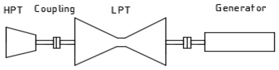
Figure 1.
T/G with one (1) LPT cylinder.
A second concept (Figure 2) with two (2) LPT cylinders is intended for countries with low heat sink temperatures (< 15 °C), and thus high volumetric exhaust flow rates. This design may also be considered for the 60 Hz market. (Note that analysis results reported here correspond to operation of a half-speed machine in the 50 Hz market).
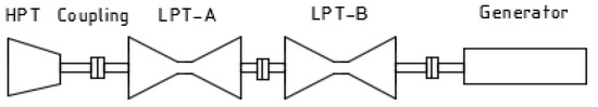
Figure 2.
T/G with two (2) LPT cylinders.
2.2. Current Investigation
This paper investigates a set of prototype configurations of the AM600 T/G shaftline. The proposed baseline LPT rotor is believed to be the longest rotor with the highest power and torque ever proposed for a Rankine steam cycle machine. As such the design represents a significant design challenge. As a first step in the design process, the prototype design was developed based on the required steam flow path and then analyzed here for torsional characteristics.
The 3D model of the shaftline configurations that were created in CATIATM V5 [24] are used to perform torsional dynamic analysis in ANSYS® 19.0 Workbench [25] to find the torsional natural frequencies and mode shapes. The separation of the frequencies will be evaluated with respect to the dominant excitation frequencies for the target markets (50 Hz for general grid disturbances and 100 Hz for negative sequence currents).
Modelling includes detailed configurations for the T/G shaftlines being considered with the L-0 blades modelled as an additional localized mass moment of inertia. Results are considered to be indicative of the potential for the AM600 design, but are not based on a specific vendor design.
ANSYS® results were verified by use of simplified theoretical calculations by application of the lumped mass approach. In this approach, Newton’s second law of motion is employed on a simplified mass-spring shaftline model wherein free-free undamped vibration is assumed.
2.3. Lumped Mass Approach
In the lumped mass approach, the mass moment of inertia of the rotating assemblage is segmented and lumped at stations that are then connected by massless springs. For example, using this approach, lumped masses along the T/G shaftline (e.g., HPT, LPT, and generator rotor) can each be represented by a single station, with stations then connected by massless springs. The solution of the lumped mass approach can be obtained by various means (e.g., the TMM or the DSM) [7]. The DSM is described as follows.
Free vibration occurs when a system vibrates under the action of forces integral to the system itself due to initial deflection (e.g., self-weight for a 1D, linear system), and under the absence of influence of other externally applied forces. The system will vibrate at one or more of its natural frequencies based on the properties of the system dynamics, as determined by the system stiffness and mass distribution.
In actual practice, damping (e.g., internal molecular friction, viscous damping, and aero dynamic damping) characteristics of the system will cause dissipation of vibration energy at increasing displacement and vibratory velocities, resulting in control of the amplitude of the free vibration.
Damping has very little influence on natural frequency of most systems, and hence, studies for natural frequencies generally ignore damping. However, damping plays a significant role in restraining the amplitude at resonance.
A simplified rotor system is shown in Figure 3. Frictionless supports and free-free boundary conditions are assumed. The method using Newton’s second law of motion, with the help of the free body diagram in Figure 4 may be used to analyze a three DOF (or more) rotor system [26].
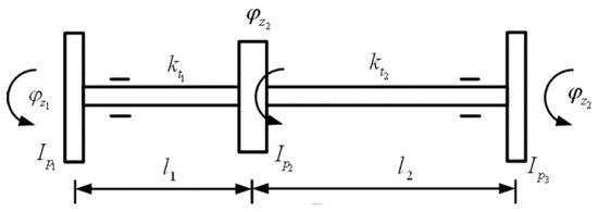
Figure 3.
A three (3) DOF torsional system.
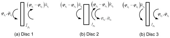
Figure 4.
Free body diagrams for the discs.
For the system shown in Figure 4, a T/G shaftline with three (3) DOF, the general equation of motion in cylindrical coordinates is given by Equation (1) as follows [26]:
where I, C, K represent the mass moment of inertia, damping, and stiffness matrices, T constitutes external torque, and its derivatives represent angular displacement, angular velocity, and angular acceleration.
The simplified cylindrical equation of motion for free-free (i.e., T = 0) and undamped vibration (i.e., C = 0) is given by Equation (2) as follows:
From the free body diagrams of individual discs, three equations of motion for free torsional vibration are then expressed using the matrix formulation per Equation (3) below:
For free vibration with Simple Harmonic Motion (SHM) is provided per Equation (4) as:
where: = the torsional natural frequency (rad/s),
I = the mass moment of inertia matrix (kg-m2),
K = rotational stiffness matrix (Nm/rad), and
= the mode shape (-)
To determine the torsional natural frequency of the system two (2) methods can be employed: (i) By use of the characteristic equations, and (ii) by formulation of an eigenvalue problem. Here, the focus will be on the second method.
The formulation of an eigenvalue problem is a more general form for obtaining natural frequencies and mode shapes and this approach can easily be solved by computer routines. The eigenvalue problem of Equation (4) gives natural frequencies, and eigenvectors represent mode shapes. Equation (5) can be written as:
with:
On multiplying both sides by the inverse mass matrix in Equation (5), we get the standard eigenvalue problem of the following form per Equation (6):
where:
The eigenvalue and eigenvector of the matrix [D] can be obtained conveniently by hand calculations for a matrix size up to 3 × 3. However, for the large size matrices for multi-DOF rotor systems, standard Finite Element (FE) software (e.g., ANSYS® [25]) can be used. The square root of the eigenvalues will give the torsional natural frequencies and corresponding mode shapes.
2.4. Finite Element Method (FEM)
Later developments of the DSM led to the evolution of the FE approach. Zienkiewicz [3] worked to develop computational schemes for quick solutions considering computing power of the day, and for general programs which could address a wide range of problems.
For modelling in ANSYS®, as reported here, the global matrices are generated and used for finding natural frequencies by adopting: (i) Characteristics equations and (ii) formulating an eigenvalue problem [27].
In summary, the FEM is a computer based numerical technique for calculating the behavior and strength of engineering structures. FEM modelling can be used to calculate mechanical vibration, stress, deflection, buckling behavior, and various other phenomena. Using this method, a real object is discretized into a large number of finite elements. A variety of element shapes can be used such as cubes, tetrahedrons, and quadratics. With the help of mathematical equations, the analysis combines individual behaviors to predict the overall behavior of the actual object.
2.5. Acceptance Criteria—Torsional Frequency Margin
Frequency margin is defined as the difference between a natural frequency and the excitation frequency [2]. If the design of the T/G shaftline (powertrain) does not have a sufficient frequency margin, cyclic fatigue damage to the shaft components such as couplings, LPT blades, and retaining rings can occur.
As discussed previously, the T/G shaftline must avoid resonance at 1× and 2× grid frequency (50 Hz and 100 Hz). A generator fault can create a large torque at 2× line frequency (i.e., several times operating torque). The International Standards Organization (ISO) provides recommendations for the torsional frequency margin [2].
ISO Standard ISO-22266 [2] addresses T/G interface to the grid. For various cases, specific torsional frequency margin values are listed for information and guidance. Figure 5 is a summary of the torsional natural frequency exclusion zones, as specified by ISO.
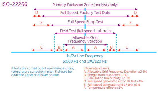
Figure 5.
ISO-22266 Torsional frequency margin [2].
3. Method of Analysis
The method and approach to developing the torsional characteristics of the AM600 T/G shaftline are outlined in the sections below.
3.1. Sizing of the Shaftline
The steps employed in the dimensioning of the AM600 T/G shaftline for input to FEM modelling are as follows:
- Prepare the steam cycle heat balance for the Valves Wide Open (VWO) condition.
- Using steam flows and extraction pressures from the heat balance, determine for each turbine stage the blade length and pitch diameter using impulse design for the HPT and reaction design for the LPT.
- Consider blade spacing along each rotor based on blade dimensions and spacing from installed rotors.
- Develop the rotor outline dimensions based on the pitch diameters and spacing from above.
- Complete the outline of the rotor design by dimensioning the length and diameter of shaft seals, journal bearings, connecting shaft, and couplings based on rotor dimensions from installed machines scaled to the AM600, based on engineering judgment.
- Develop the rotor internal spacing for the welded drum type rotor by allowing for spaces between the drums consistent with existing designs. Monoblock rotors are considered to be solid.
- Complete the T/G shaftline by adding a conventional half speed generator rotor that matches the capacity of the AM600. Assume static excitation.
The shaftline is then assembled from the HPT to the LPT to the generator using bonded contact between the rotors (no slip condition) in CATIATM. This assembly was then discretized for analysis in ANSYS®.
3.2. Geometric Modelling Using CATIATM V5 R20
The rotordynamic behaviour assessment begins with building a 3D solid model for the coupled shaftline to represent the geometry developed above. Following the steps outlined in Section 3.1, the model was developed using CATIATM V5 (Figure 6). This design considers the single LPT cylinder configuration. Due to the large span of this rotor, the baseline model considers a low mass, high stiffness, welded drum type LPT rotor.
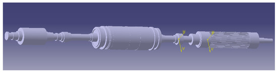
Figure 6.
3D CATIATM model of the baseline AM600 T/G shaftline.
3.3. Discretization of the Model Using ANSYS® 19.1
Supporting analysis here is based on ANSYS® Workbench Version 19.0 [24], a Computer Aided Engineering (CAE) program that employs the FEM. The computational scheme employed in the solution of the eigenvalue problem applies the Block Lanczos extraction method that uses the sparse direct solver. This method is available for large symmetric eigenvalue problems even when poorly shaped elements exist. The block shifted Lanczos algorithm is a variation of the classical Lanczos algorithm, where the Lanczos recursions are performed using a block of vectors, as opposed to a single vector. This method employs an automated shift strategy to efficiently extract the number of eigenvalues requested [28].
3.3.1. Slicing
First, the 3D solid model of the shaftline is imported to the ANSYS® Workbench. To prepare a complete representation of the shaftline, detailed information is required. In the DesignModeler, the shaftline is broken into smaller segments using a process called slicing. Each segment has a cross-section divided according to stiffness and a mass attributed to the associated material properties, as defined in the ANSYS® engineering data source (see Figure 7).
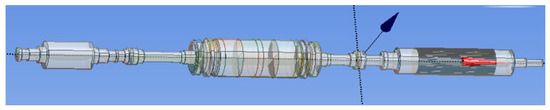
Figure 7.
Sliced shaftline.
3.3.2. Mesh Development
After slicing the model in the ANSYS® Workbench, for analyzing the large system such as nuclear steam T/G shaftline, a hybrid mesh is the best scheme when considering modelling time and solution accuracy. In the main shaft line sections, the hexahedral mesh was employed, and in the complex sections such as the generator rotor (including slots, fillets and steps), the tetrahedral mesh was employed. The generator rotor portion is shown in Figure 8 below to illustrate the hybrid mesh.
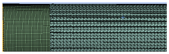
Figure 8.
Hybrid mesh on the generator rotor portion.
To ensure the reliability of the results, a mesh dependency study (see Section 3.6) was carried out to check the convergence of the results by gradually reducing the element size (refining) until the torsional natural frequencies are unchanged, irrespective of element size. Based on convergence checks, the final mesh consisted of 129,562 elements and 300,869 nodes. The meshed FE model of the T/G shaftline is shown in Figure 9.
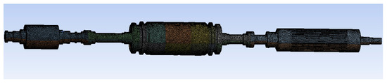
Figure 9.
Meshed shaftline model.
3.4. Boundary Conditions and Modelling of Blades
As shown in Figure 10, the boundary conditions were defined by constraining the sliced shaft along the axial centerline to ensure that only torsional frequencies and modes shapes are calculated.
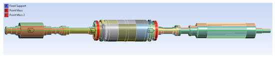
Figure 10.
Applying boundary conditions and adding L-0 blades to the model.
The additional mass of the L-0 blades on the LPT was modelled by applying the associated mass moment of inertia at Locations B and C.
3.5. Material Properties
The material properties (12% Chrome forged steel) are taken as typical values at the operating conditions of the shaftline, as given in Table 1.

Table 1.
Shaftline material properties.
3.6. Mesh Independency Study
To establish the accuracy of the modal analysis results, the mesh relevance was kept to 100 and fine relevance center to ensure the best quality mesh. A grid convergence study was performed by developing three different meshes (i.e., with coarse, medium, and fine grid) for a shaftline with a welded drum LPT cylinder to calculate the torsional natural frequencies to determine how the mesh resolution affects modal simulation results.
Table 2 shows the how the mesh resolution affects the number of the nodes and simulation time and the modal frequencies for the three cases analyzed. The lumped mass model’s first three (3) mode frequencies are also listed for comparison in this table (see Section 4.2).
Table 2.
Mesh size, number of nodes, and meshing and solving time 1.
It is important to note that the mesh resolution plays an important role in the final modal frequency results. The mesh nodes need to be small to resolve the complexities on the generator slots, couplings, and the shoulder fillets. From Table 2, modal frequencies are less dependent on the mesh refinement.
Modes 1 and 7 remained at 0 Hz and 179.4 Hz frequency, respectively, throughout the refinement of the mesh. The rest of the modes showed a maximum of 1.5% decrease of the frequencies value from coarse to fine mesh. The fine mesh leads to the most reasonable calculation of the natural frequencies of the shaftline, whereas the natural frequencies of medium mesh are slightly better than in course mesh. It is clear that the simulation time is highly dependent on the mesh resolution. Fine mesh requires the long simulation time and high computational capacity, but due to the required level of accuracy of the natural frequencies results, it is further employed for calculation of natural frequencies and mode shapes for all shaftline configurations.
Considering that the prototype rotor is representative, but not a definitive design, and that any final design will be vendor dependent, the convergence of eigenvalues on grid size and the comparison to lumped mass approximations provides adequate assurance that the results reported here are representative of the expected design.
4. Results and Discussion
4.1. FEM Results in ANSYS®
The preceding section outlines procedures that were followed for the modal analysis of the shaftline with a single cylinder LPT welded drum rotor. A second case, a shaftline with two (2) LPT cylinders, was also considered. For comparison, each of these cases was analyzed for both welded drum and the monoblock configurations. Results for the first seven torsional modes are summarized in Table 3 below.
Table 3.
Torsional natural frequencies of the shaftline.
4.2. Confirmation Using Simplified Model
The lumped mass method was used with the shaftline properties given in Table 1 to perform a lumped mass confirmatory analysis of the baseline model. The HPT, LPT, and generator rotor were modelled as discs connected by massless springs. Figure 11 illustrates the simplified model of the single cylinder monoblock rotor as a vibrating system with three (3) DOF [29].
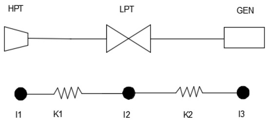
Figure 11.
T/G mass-spring shaftline model.
Table 4 provides useful polar moment of inertia and torsional stiffness formulae for solid and annular shaft geometries. L, D and d represent the element length, external and internal diameters, respectively. and G are the density and modulus of the rigidity of the material. The modulus elasticity for the material is specified above (see Table 1). The calculated shaftline properties for torsional dynamic analysis are shown in Table 5.
Table 4.
Torsional parameter formulae [29].
Table 5.
Shaftline mass-spring modelling properties.
With the properties calculated in Table 5, the eigenvalue problem was formulated to calculate the torsional natural frequencies in a three (3) DOF system. This approach resulted in a 3 × 3 matrix, producing the first three modes of torsional natural frequencies, as shown and compared with ANSYS® results in Table 6.
Table 6.
Comparison of torsional frequencies.
4.3. Evaluation against Exclusion Zone
Considering the grid frequency of 50 Hz, the results given in Table 3 were evaluated against the frequency exclusion zones, as per the ISO-22266 standard given in Figure 5 (for analysis purpose only), as presented in Figure 12 and Figure 13.
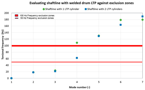
Figure 12.
Evaluating welded drum LPT cylinder shaft frequency.
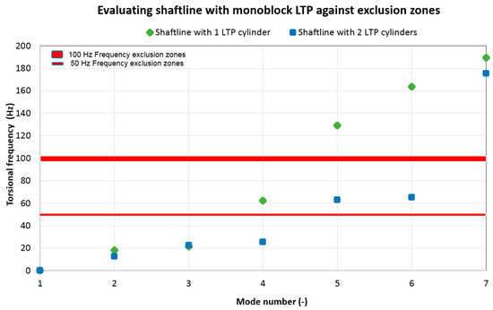
Figure 13.
Evaluating monoblock LPT cylinder shaft frequency.
4.4. Discussion
4.4.1. General
In this paper, the FE modelling was done using the software ANSYS® 19.0 for the 3D model of the shaftline, as created in CATIATM V5. This allows a high level of geometric detail (e.g., generator rotor slots) to be included to take advantage of the capabilities of 3D modelling and to ensure good accuracy of the results. The L-0 blades were modelled as lumped mass inertias in Workbench. The material properties for density, elastic modulus, and Poisson’s ratio were defined and assumed to be homogenous and isotropic throughout the shaftline. Bonded contact is applied between the couplings, rotors, and LPT drums. This form of contact implies no sliding or separation of contact pairs and allows for linear solutions (required for torsional dynamics analysis). A mesh dependency study was carried out to add confidence to the FE results. For the validation of the FE results, the lumped mass approach was employed on a system with three (3) DOFs and the first three (3) modes of the torsional natural frequencies results show agreement to within 3%. This lends confidence to the modelling effort. Table 3 provides results of the FE modelling.
4.4.2. Shaftline Robustness in Relation to Torsional Vibration
Fatigue damage is always possible when a natural frequency exists at the same frequency as the system stimuli (vibratory forcing functions). In power generating equipment, it is important to stay away from 1× and 2× of the grid frequency (50 Hz and 100 Hz). The 1x exclusion zone helps to reduce the response to grid transient disturbances including electrical faults. A generator will also create a 2× stimulus due to negative sequence currents, which results in the generator creating and oscillation torque at 2× grid frequency during normal operation. Therefore, eigenvalues close to 1× and 2× grid frequencies must be avoided.
Figure 12 and Figure 13 compare ANSYS® results for the natural frequencies for Modes 1 through 7 against the exclusion zones. ISO–22266 [2] recommends the frequency range for exclusion zones. With these recommendations, natural frequencies must be avoided within of 50 Hz and of 100 Hz. The evaluation provides indications that are promising for the intended purpose of the AM600 T/G shaftline. First, the torsional natural frequencies that are close to 1× and 2× grid frequency are few and widely separated. Second, the mode shapes illustrate the expected shaftline response at those particular frequencies [23].
The ‘standard’ Mode 1 frequency (0 Hz) indicates rigid and free rotation. For the seven modes that were extracted, the torsional frequencies increased from zero to 190 Hz.
For the single cylinder design, with either welded drum or monoblock construction, there is a wide separation between the highest subsynchronous eigenvalue and the lowest synchronous value, for the baseline configuration (single LPT, welded drum), the jump is from 23 Hz to 109 Hz from Mode 3 to Mode 4. For the single LPT, monoblock configuration, the jump is from 21 Hz (Mode 3) to 63 Hz (Mode 4), and then to 129 Hz (Mode 5). Both of these cases exhibit significant spans within which to tune the final design away from the exclusion zones near 50 and 100 Hz. Configurations with two (2) LTP cylinders again show good separation.
Generally, there is a greater separation of the modes for the welded drum type LTP shaft as compared to the monoblock type LTP cylinders. Even though there is a mode near 100 Hz frequency (i.e., 108.9 Hz) this mode can easily be shifted by the inertia tuning method described in Section 1.5 and still ensure the safe operation of the shaftline.
The CATIATM modelling and ANSYS® analysis provide confidence that detailed design and tuning of the single cylinder LPT design by an experienced turbine vendor organization can result in a machine that provides more robust resistance to torsional excitation. Additionally, the monoblock type rotors were found to have lower frequencies than those of welded drum type rotors. These results agree with the theory that indicates that resonant frequencies increase with a decrease in the mass of the system (e.g., see Equation (5)).
4.4.3. Previous Studies
In a previous study, Eckert and Huster [14] used direct measurement to evaluate theoretical calculations of the torsional natural frequencies and mode shapes for the 700 MWe steam turbine shaftline with two (2) welded drum LPT rotors. They then classified the typical groups of mode frequencies, which are compared to the AM600 natural frequencies of the shaftline with two (2) welded drum LPT rotors in Table 7 as follows:
Table 7.
Comparison of torsional frequencies.
It is clear from Table 7 that the AM600 results are comparable to results obtained for the 700 MWe (fossil) T/G shaftline. Further, the results for the shaftline with two (2) monoblock LPT cylinders are in general agreement with the results obtained by Chan and Dennis [30] using the discrete mass-spring method for the system with two (2) monoblock LPT cylinders in which some of the modal frequencies were lower but still within a similar range.
4.4.4. Mode Shapes
For the purpose of analysis and evaluating the results against the frequency exclusion ranges, this paper focuses on the mode frequencies that are close to the exclusion ranges. Examples of frequencies and deformations, as calculated by ANSYS®, are provided in Figure 14, Figure 15, Figure 16 and Figure 17.
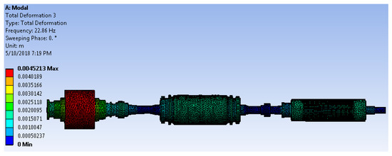
Figure 14.
Concept 1 Mode 3 torsional natural frequency and deformation.
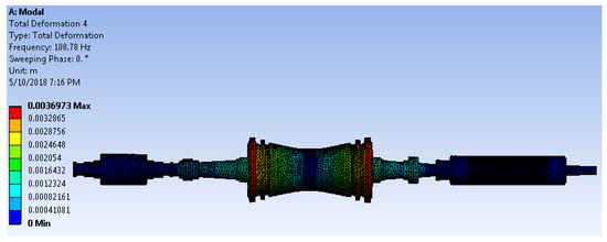
Figure 15.
Concept 1 Mode 4 torsional natural frequency and deformation.
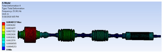
Figure 16.
Concept 2 Mode 4 torsional natural frequency and deformation.
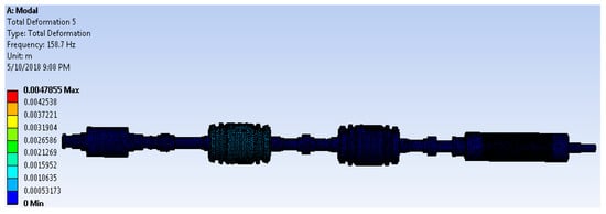
Figure 17.
Concept 2 Mode 5 torsional natural frequency and deformation.
In each Figure, the torsional natural frequency of vibration is indicated and the colors red and blue indicate maximum and minimum deformation (mode shapes when animated), respectively. In Figure 14, the 22.9 Hz mode can be visualized as the HPT rotor and the Generator rotor oscillates in the same direction, as opposed to the LPT rotor. In Figure 15, the 108.9 Hz mode, the largest deformation is at the locations of the L-0 blades (possibly due to the centrifugal forces of the lumped inertia blades) and the LPT rotor body is oscillating in the opposite direction.
Figure 16 shows that the Mode 3 frequency is 25.3 Hz and the largest deformation is at the HPT rotor, which is oscillating in the same direction with the generator rotor with counter-rotation by the two (2) LPT rotors. In Figure 17, the frequency is 158.7 Hz and the largest deformation is on the LPT rotors that are oscillating in the same direction.
The generator modes are important because they are the mechanisms by which T/G can be excited by the transient air gap torques. If the generator participates in a mode whose frequency is close to 2× the grid frequency, negative sequence current torques will excite it. If the mode also has the participation some of the LPT blades, there might be a very high possibility of loss of blades from fatigue due to torsional vibration. If the T/G has modes near 2× the grid frequency, it has to be modified to shift the modes away from 2× the grid frequency to avoid the damage on the L-0 blades. Here, from Figure 15 the 108.9 Hz mode shape indicates no participation of the generator rotor in the torsional vibration and therefore the design is safe from transient air gap torques.
5. Conclusions
The torsional natural frequencies and the mode shapes of the prototype AM600 T/G shaftline were successfully generated using a combination of CATIATM and ANSYS® modelling. The most critical frequencies for the target markets are those near one and two times the grid frequency (i.e., 50 Hz and 100 Hz).
From the ANSYS® analysis results, the frequencies that are closest to 50 Hz are 62.4 Hz and 63.0 Hz in Mode 4 of the single cylinder monoblock type LPT rotor and Mode 5 of the double cylinder monoblock type LPT rotor, respectively. The frequencies that are closest to 100 Hz are 108.9 Hz and 129.3 Hz in Mode 4 of the single cylinder welded drum type LPT rotor and Mode 5 of the single cylinder monoblock LPT rotor, respectively. When evaluated against the exclusion zones in Figure 12 and Figure 13, this shows excellent separation for the simplified models considered here, and therefore the AM600 T/G shaftline is robust relative to torsional vibration.
Good fidelity was demonstrated between the detailed ANSYS® model and simplified lumped mass modelling based on first principles. However, the 3D FEM shaftline model in ANSYS® is considered to provide more accurate and realistic results, as it excludes the inherent assumptions of the 1D lumped mass-spring model. The lumped mass approach assumes the rigid rotor bodies (i.e., HPT, LPT and Generator rotors) and is more applicable for non-stepped shafts. Visualization of the torsional mode is enhanced by 3D modeling, which also includes rigid shaft modes (not possible using the 1D approach). Modal analysis by 3D FEA allows the visualization of the Eigen modes and can also be used to identify the modes that are not measured.
Although 3D modelling in theory can capture all the geometric details, this approach requires significant development effort and advanced computational resources.
This first effort at rotordynamic analysis of the prototype AM600 T/G shaftline produced results that met expectations that the number and separation of torsional eigenvalues would be promising for the AM600 T/G shaftline design concept, as related to robust performance in less than robust grids.
Turbine Vendor Design: The prototype AM600 T/G shaftline torsional vibration characteristics reported here are based on a steam flow path configuration, which is believed to support the proposed AM600 turbine cycle heat balance. However, the design, dimensioning, and rotating masses included in the modelling are best estimates and not based on any particular proven design concept or family of LPT blading. To effect the AM600 T/G design and make it ready for delivery requires a complete design effort from a seasoned design team at a T/G vendor, one with extensive nuclear steam turbine experience. Such an effort would involve activities such as: (i) Final heat balance preparation, (ii) rotating blade design, (iii) rotor design, (iv) material selection, (v) stress and structural analysis, and (vi) development and testing of any new blading, which is required. However, the analysis here is believed to demonstrate a ‘proof of concept’, which lends confidence for further development work in this area.
Transient Response due to 3 Phase Short Circuit Torque: The detailed modelling described above will provide a useful basis for torsional analysis of excitation associated with three phase short circuit faults. Additionally, known as per unit air gap torque, the three-phase short circuit torque can generate momentary torque as high as twelve (12) times the generator rated torque and can result in damage of turbine blades, couplings, and retaining rings. In future research, the maximum shear stresses will be evaluated on the LPT rotor section near the generator using the CATIATM/ANSYS® model developed here.
Author Contributions
T.M. contributed T/G shaftline baseline dimensioning, rotordynamic modeling analysis, and evaluation of results. R.M.F. contributed steam flow path design, rotor construction, final shaftline dimensioning, verification approach, and final editing.
Funding
This research received no external funding.
Acknowledgments
The authors wish to acknowledge the support of the KEPCO International Nuclear Graduate School (KINGS) and contributions from KINGS Nuclear Steam Cycle Development by the NPP class of 2018.
Conflicts of Interest
The authors have no conflicts of interest to declare.
Abbreviations and Acronyms
| 1D | One Dimensional |
| 3D | Three Dimensional |
| ABWR | Advanced Boiling Water Reactor |
| AM600 | Advanced Modern 600 (MWe) |
| ANSYS® | Analysis System |
| AP1000 | Commercial 1200 MWe NPP by Westinghouse |
| APR1400 | Commercial NPP by KHNP |
| CAE | Computer Aided Engineering |
| CATIA | Computer Aided Three-dimensional Interactive Application |
| CIGRE | (International Council on Large Electric Systems) |
| DOF | Degree(s) of Freedom |
| DSM | Direct Stiffness Method |
| EPR | Commercial 1500 MWe NPP by Areva/EDF |
| EPRI | Electric Power Research Institute |
| FE | Finite Element |
| FEA | Finite Element Analysis |
| FEM | Finite Element Method |
| GE | General Electric |
| GPa | GigaPascal |
| HPT | High Pressure Turbine |
| Hz | Hertz |
| ISO | International Standards Organization |
| KEPCO | Korea Electric Power Corporation |
| kg | kilogram (mass) |
| KINGS | KEPCO International Nuclear Graduate School |
| L-0 | Last Stage Turbine Blading |
| LP | Low Pressure |
| LPT | Low Pressure Turbine |
| m | meter |
| MPa | MegaPascal |
| MWe | MegaWatts (electric) |
| MWt | MegaWatts (thermal) |
| N | Newton (force) |
| NPP | Nuclear Power Plant |
| NPTEL | National Program on Technology Enhanced Learning |
| PC | Personal Computer |
| SHM | Simple Harmonic Motion |
| T/G | Turbine—Generator |
| TMM | Transfer Matrix Method |
| USA | United States of America |
| VVER | Commercial NPP by ROSATOM Group |
| VWO | Valve Wide Open |
| Symbols | |
| C | damping coefficient matrix |
| d | internal diameter |
| D | outside diameter |
| F | force |
| G | modulus of rigidity |
| I | mass moment of inertia matrix |
| mass moment of inertia | |
| K | stiffness matrix |
| total stiffness | |
| L | length |
| M | mass |
| n | number |
| torsional natural frequency | |
| angular displacement | |
| density |
References
- Field, R.M. AM600: A new look at the nuclear steam cycle. Nucl. Eng. Technol. 2016, 49, 621–631. [Google Scholar] [CrossRef]
- ISO. Mechanical Vibration—Torsional Vibration of Rotating Machinery; ISO 22266-1; International Organization of Standardization: Geneva, Switzerland, 2008. [Google Scholar]
- Zienkiewicz, O.C.; Glowinski, R.; Robin, E.Y. Energy Methods in Finite Element Analysis; Wiley: New York, NY, USA, 1979; p. 7. ISBN 0247199723. [Google Scholar]
- Steam Turbine-Generator Torsional Vibration Interaction with the Electrical Network; EPRI Report No. 1011679; Electric Power Research Institute (EPRI): Palo Alto, CA, USA, 2005.
- Chen, Y. An investigation of excitation method for torsional testing of a large-scale steam turbine generator. J. Vib. Acoust. 2004, 163–177. [Google Scholar] [CrossRef]
- Dunlop, R. Torsional oscillations and fatigue of steam turbine shafts caused by system disturbances and switching events. In CIGRE International Conference on Large High Voltage Electric Systems; CIGRE: Paris, France, 1980. [Google Scholar]
- Scheepers, R.; Heyns, P. A comparative study of finite element methodologies for torsional vibration response calculations of bladed rotors. J. Mech. Sci. Technol. 2016, 30, 4063–4074. [Google Scholar] [CrossRef]
- Szolc, T. Discrete continous modeling of rotor systems the analysis of coupled lateral torsional vibrations. Int. J. Rotating Mach. 2000, 6, 134–148. [Google Scholar] [CrossRef]
- Ricci, R.; Turozzi, G.; Pennacchi, P.; Pesatori, E. Modeling and model updating of torsional behaviour of an industrial steam turbo generator. J. Eng. Gas Turbines Power 2010, 132, 1–6. [Google Scholar] [CrossRef]
- Nelson, H.; Chivens, D. The natural frequencies and critical speeds of a rotating, flexible- shaft - disk system. J. Eng. Ind. 1975, 97, 881–886. [Google Scholar]
- Ambrosio, F.; Chatelet, E. Toward global modelling approaches for dynamic analyses of rotating assemblies of turbomachines. J. Sound Vib. 2005, 282, 163–177. [Google Scholar]
- Stephenson, R.; Aora, R.; Rouch, K. Modelling of rotors with axisymmetric solid harmonic elements. J. Sound Vib. 1989, 131, 431–443. [Google Scholar] [CrossRef]
- Vance, J.; Tripp, H.; Murphy, B. Critical speeds of turbomachinery: Computer predictions vs. experimental measurements—Part I: The Rotor Mass Elastic Model. J. Vib. Acoust. Stress Reliab. Des. 1987, 109, 1–7. [Google Scholar] [CrossRef]
- Eckert, L.; Huster, J. Calculation and measurement of torsional vibrations in large steam turbosets – new technique. Noise Vib. Worldw. SAGE J. 1999, 30, 5–11. [Google Scholar]
- Jacquet-Richardet, G.; Ferraris, G. Frequencies and modes of rotating flexible bladed disc-shaft assemblies: A global cyclic symmetric approach. J. Sound Vib. 1996, 191, 901–915. [Google Scholar] [CrossRef]
- Omprakash, V. Analysis of bladed discs—A review. Shock Vib. Dig. 1988, 11, 14–21. [Google Scholar] [CrossRef]
- Petrov, E.P. A method for use of cyclic symmetry properties in analysis of nonlinear multiharmonic vibrations of bladed discs. J. Turbomach. 2004, 126, 175–183. [Google Scholar] [CrossRef]
- Mbaye, M.; Soize, C.; Ousty, J. A reduced–order model of detuned cyclic dynamical systems with geometric modifications using a basics of cyclic models. J. Eng. Gas Turbines Power 2010, 132, 1–9. [Google Scholar] [CrossRef]
- Lissenden, C.J.; Lebold, M.S.; Maynard, K.P.; Trethewey, M.W. Technology Development for Shaft Crack Detection in Rotating Equipment in NPP Using Torsional Vibration; Report No.1011679; Electric Power Research Institute (EPRI): Palo Alto, CA, USA, 2005; pp. 2–13. [Google Scholar]
- Kim, Y.; Yang, B.; Kim, C. Noise source identification of small fan-BLDC motor system for refrigerators. Int. J. Rotating Mach. 2006, 2006, 1–7. [Google Scholar] [CrossRef]
- Bai, B.; Zhang, L.; Guo, T.; Liu, C. Analysis of dynamic characteristics of the main shaft system in a hydro-turbine based on ANSYS. Procedia Eng. 2012, 31, 654–658. [Google Scholar] [CrossRef]
- Bovsunovskii, A.; Chernousenko, O.; Shtefan, E. Fatigue damage and failure of steam turbine rotors by torsional vibration. Strength Mater. 2010, 42, 108–113. [Google Scholar] [CrossRef]
- Buskirk, E. Torsional Dynamics: Large 2-Pole and 4-Pole Steam Turbines Powertrains; General Electric (GE) Power and Water Report No. 4724; General Electric Company: Schenectady, NY, USA, 2013. [Google Scholar]
- CATIATM Version 5 R20. User Guide, Training and Help Manual, CATIA; Dassault Systems: Vélizy-Villacoublay, France, 2018.
- ANSYS® Version 19.0. User Guide, Training and Help Manual; ANSYS, Inc.: Canonsburg, PA, USA, 2018.
- Theory and Practice of Rotordynamics. National Programme on Technology Enhanced LEARNING (NPTEL). 23 April 2014. Available online: https://nptel.ac.in/courses/112103024/17 (accessed on 26 July 2018).
- Tiwari, R.; Guwahati, I.T. Torsional vibrations of rotors. In The Direct and Transfer Matrix Methods; Indian Institute of Technology: Assam, India, 2010; pp. 285–287. [Google Scholar]
- Rajakumar, C.; Rogers, C.R. The Lanczos algorithm to unsymmetric generalised eigenvalue problems. Int. J. Numer. Method Eng. 1991, 32, 1009–1026. [Google Scholar] [CrossRef]
- Newland, E. Mechanical Vibration Analysis and Computation; Dover Publications: New York, NY, USA, 2006; pp. 122–128. ISBN 0486445178. [Google Scholar]
- Chan, H.; Dennis, S. The transient torsional behaviour of a Turbine-Generator due to short-circuit. In International Turbine and Aeroengine Congress & Exhibition; ASME: Birmingham, UK, 2008. [Google Scholar]
© 2018 by the authors. Licensee MDPI, Basel, Switzerland. This article is an open access article distributed under the terms and conditions of the Creative Commons Attribution (CC BY) license (http://creativecommons.org/licenses/by/4.0/).