
A Comprehensive Study of Key Electric Vehicle (EV) Components, Technologies, Challenges, Impacts, and Future Direction of Development

 ,
,  ,
,  ,
, 
Abstract
1. Introduction
2. EV Types
- (1)
- Battery Electric Vehicle (BEV)
- (2)
- Hybrid Electric Vehicle (HEV)
- (3)
- Plug-in Hybrid Electric Vehicle (PHEV)
- (4)
- Fuel Cell Electric Vehicle (FCEV)
2.1. Battery Electric Vehicle (BEV)
2.2. Hybrid Electric Vehicle (HEV)
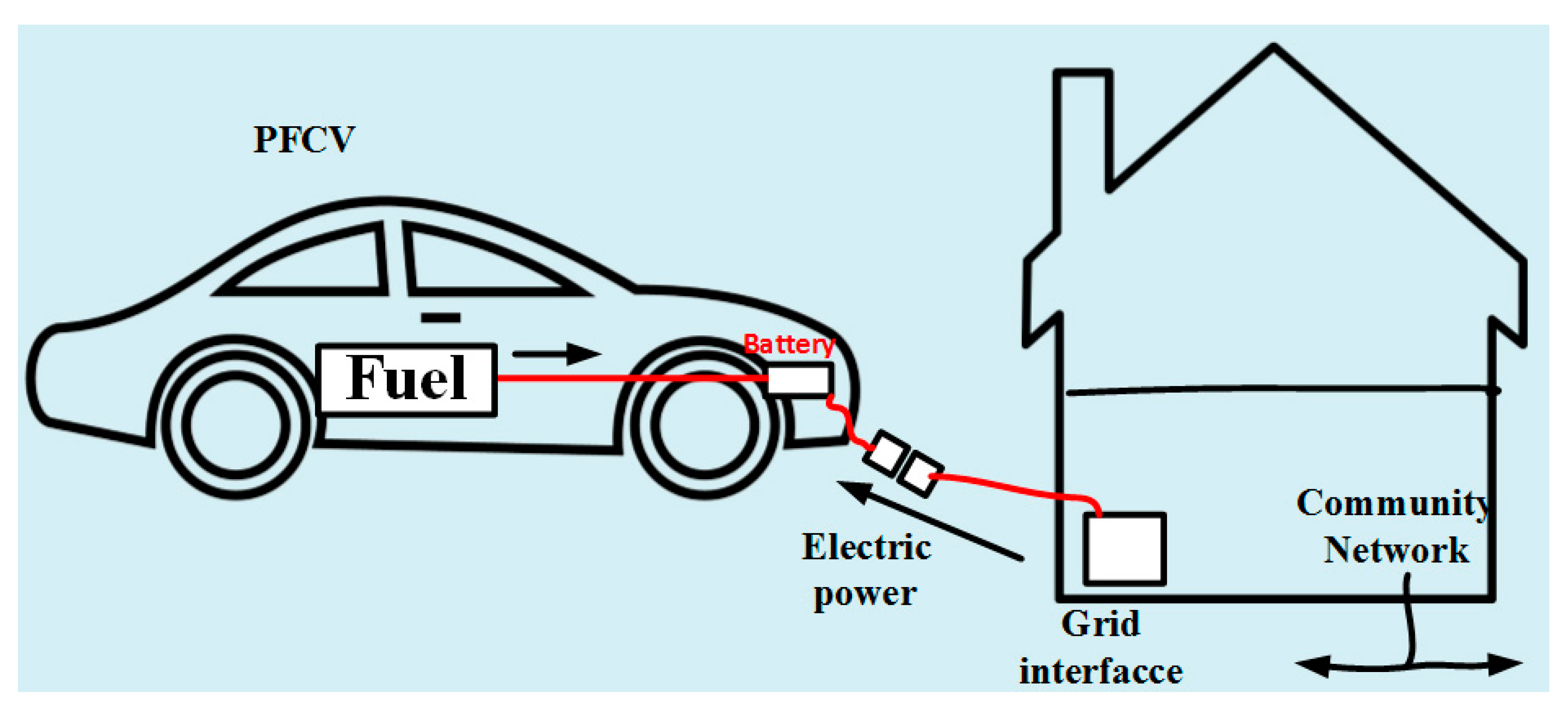
2.3. Plug-In Hybrid Electric Vehicle (PHEV)
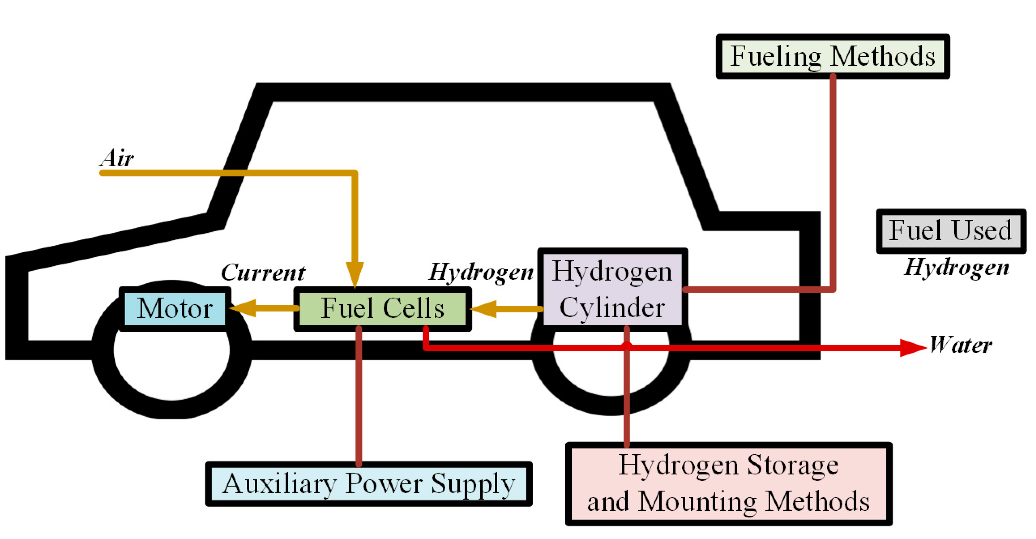
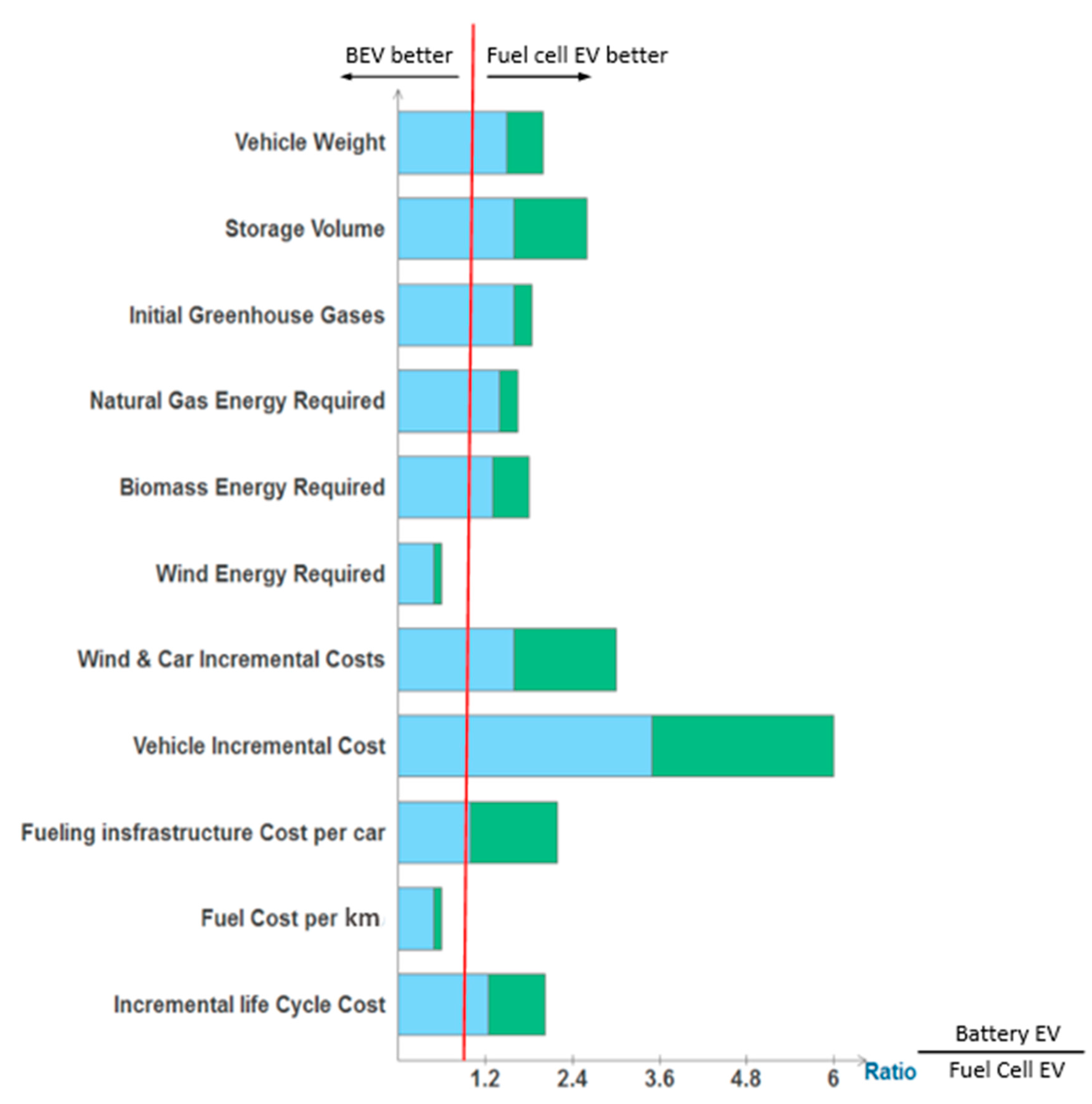
2.4. Fuel Cell Electric Vehicle (FCEV)
3. EV Configurations
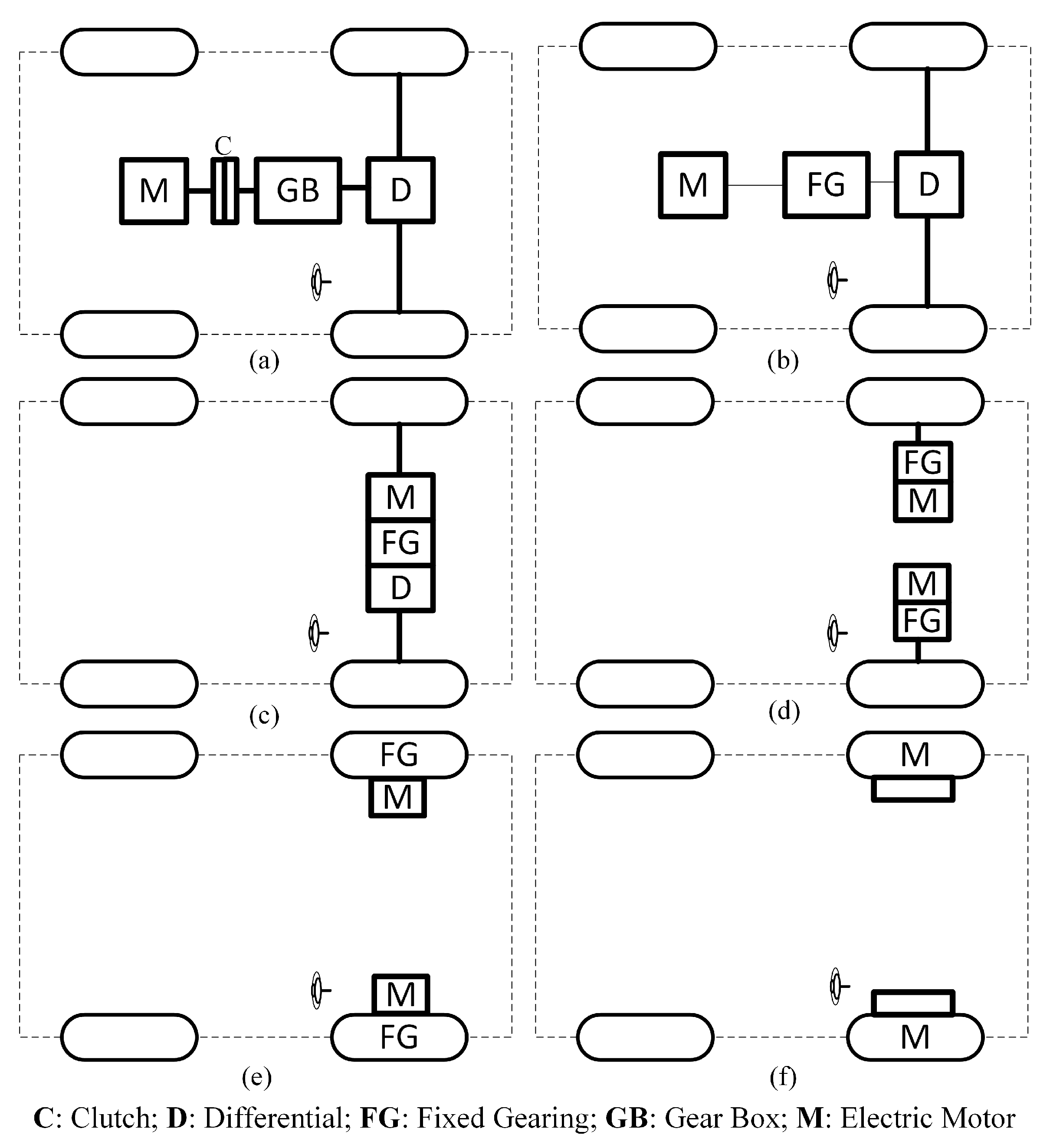
3.1. General EV Setup
3.2. HEV Setup
- (1)
- Series hybrid
- (2)
- Parallel hybrid
- (3)
- Series-parallel hybrid
- (4)
- Complex hybrid
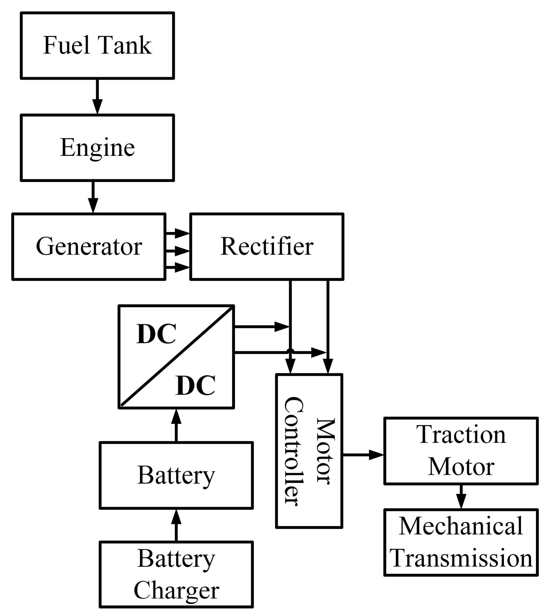
3.2.1. Series Hybrid
3.2.2. Parallel Hybrid
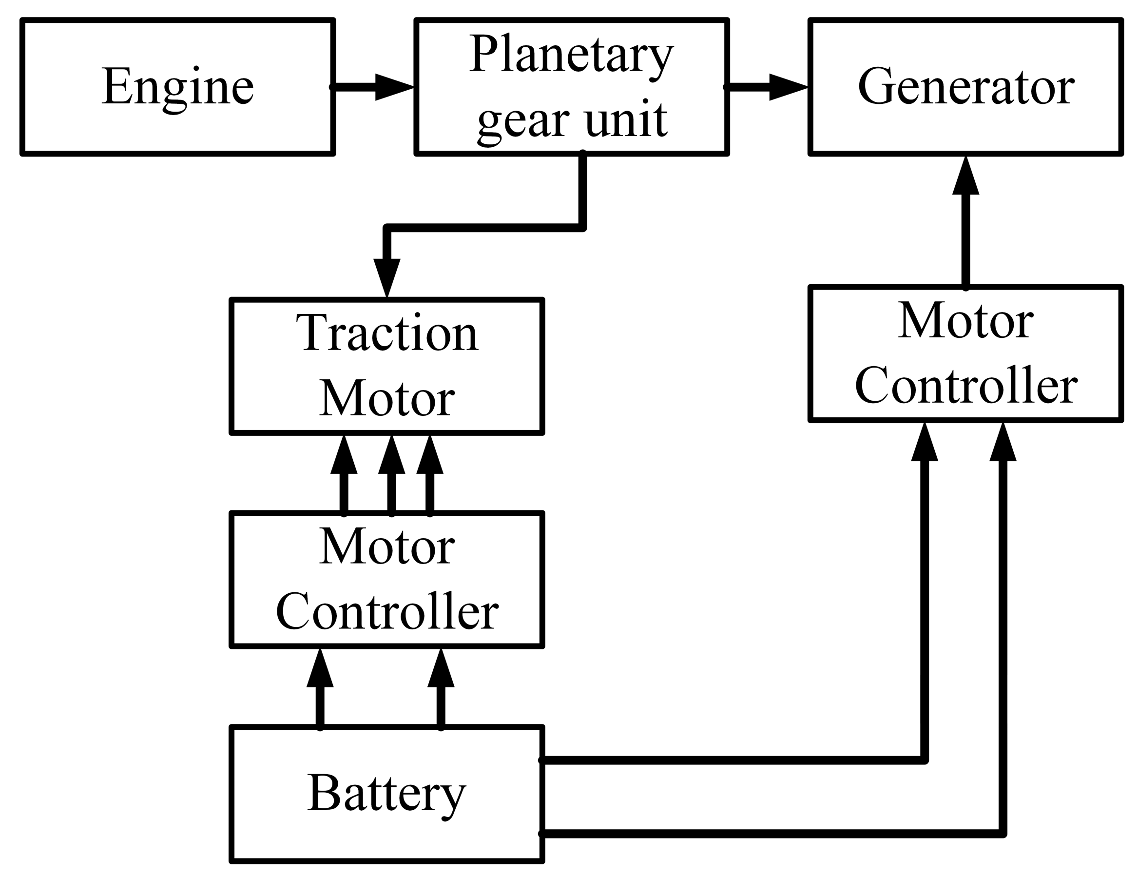
3.2.3. Series-Parallel Hybrid
3.2.4. Complex Hybrid
4. Energy Sources
4.1. Battery
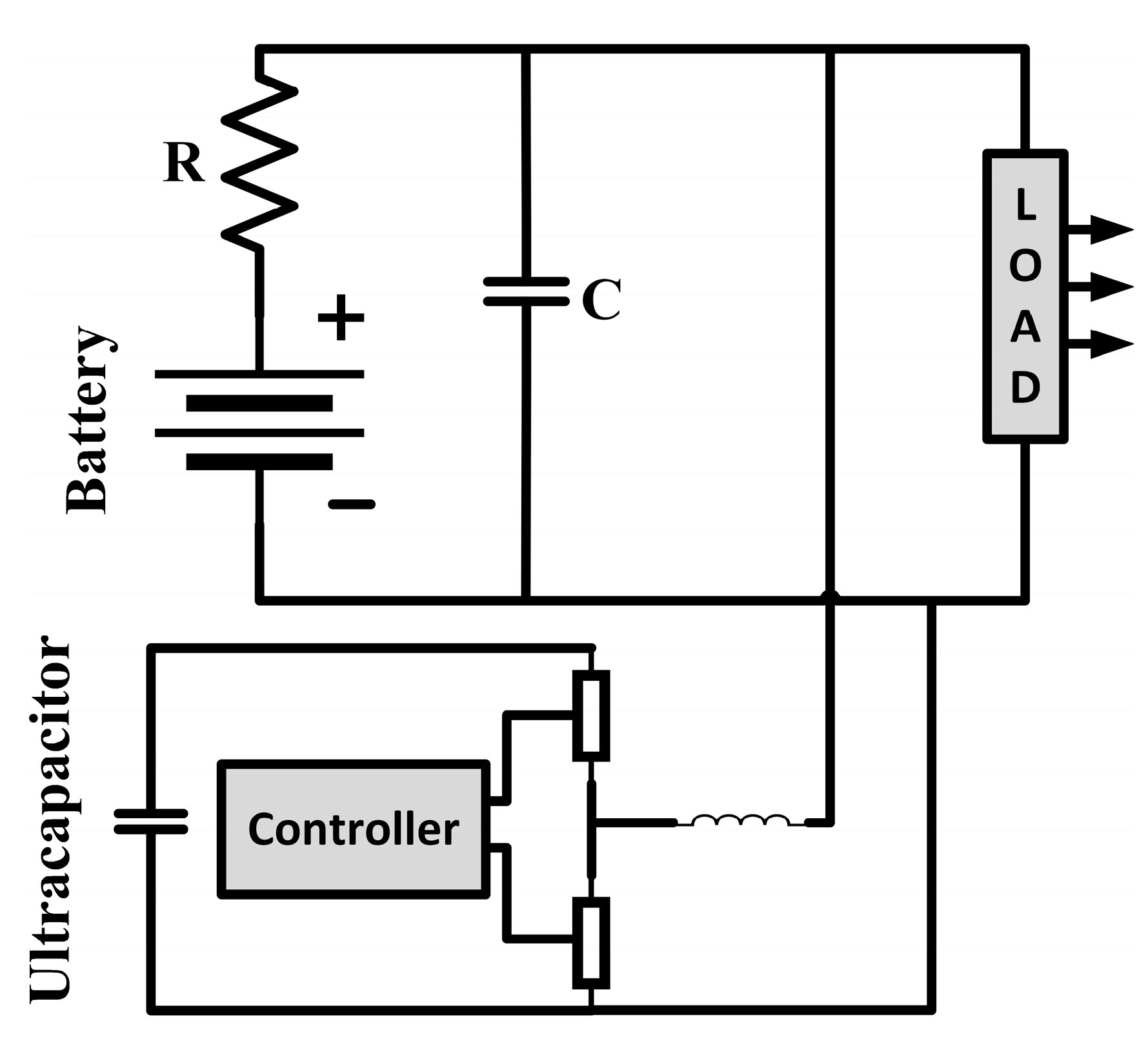
4.2. Ultracapacitors (UCs)
4.3. Fuel Cell (FC)
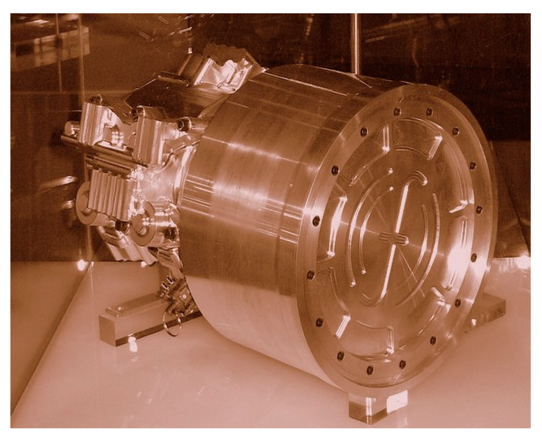
4.4. Flywheel
5. Motors Used
5.1. Brushed DC Motor
5.2. Permanent Magnet Brushless DC Motor (BLDC)
5.3. Permanent Magnet Synchronous Motor (PMSM)
5.4. Induction Motor (IM)
5.5. Switched Reluctance Motor (SRM)
5.6. Synchronous Reluctance Motor (SynRM)
5.7. PM Assisted Synchronous Reluctance Motor
5.8. Axial Flux Ironless Permanent Magnet Motor
6. Charging Systems
- SAE J2929: Electric and Hybrid Vehicle Propulsion Battery System Safety Standard
- ISO 26262: Road Vehicles—Functional safety
- ISO 6469-3: Electric Road Vehicles—Safety Specifications—Part 3: Protection of Persons Against Electric Hazards
- ECE R100: Protection against Electric Shock
- IEC 61000: Electromagnetic Compatibility (EMC)
- IEC 61851-21: Electric Vehicle Conductive Charging system—Part 21: Electric Vehicle Requirements for Conductive Connection to an AC/DC Supply
- IEC 60950: Safety of Information Technology Equipment
- UL 2202: Electric Vehicle (EV) Charging System Equipment
- FCC Part 15 Class B: The Federal Code of Regulation (CFR) FCC Part 15 for EMC Emission Measurement Services for Information Technology Equipment.
- IP6K9K, IP6K7 protection class
- −40 °C to 105 °C ambient air temperature
6.1. AC Charging
- Level 1: The maximum voltage is 120 V, the current can be 12 A or 16 A depending on the circuit ratings. This system can be used with standard 110 V household outlets without requiring any special arrangement, using on-board chargers. Charging a small EV with this arrangement can take 0.5–12.5 h. These characteristics make this system suitable for overnight charging [5,46,81].
- Level 3: This system uses a permanently wired supply dedicated for EV charging, with power ratings greater than 14.4 kW. ‘Fast chargers’—which recharge an average EV battery pack in no more than 30 min, can be considered level 3 chargers. All level 3 chargers are not fast chargers though [46,82]. Table 19 shows the AC charging characteristics defined by Society of Automotive Engineers (SAE).
6.2. DC Charging
- Level 1: The rated voltage is 450 V with 80 A of current. The system is capable of providing power up to 36 kW.
- Level 2: It has the same voltage rating as the level 1 system; the current rating is increased to 200 A and the power to 90 kW.
- Level 3: Voltage in this system is rated to 600 V. Maximum current is 400 A with a power rating of 240 kW. Table 20 shows the DC charging characteristics defined by Society of Automotive Engineers (SAE).
6.3. Wireless Charging
- Combined Charging System (CCS)
- CHAdeMO (CHArge de MOve, meaning: ‘move by charge’)
- Supercharger (for Tesla vehicles)
7. Power Conversion Techniques
7.1. Converters for Wired Charging
7.2. Systems for Wireless Charging
8. Effects of EVs
8.1. Impact on the Power Grid
8.1.1. Negative Impacts
- Voltage instability: Normally power systems are operated close to their stability limit. Voltage instabilities in such systems can occur because of load characteristics, and that instability can lead to blackouts. EV loads have nonlinear characteristics, which are different than the general industrial or domestic loads, and draw large quantities power in a short time period [81,122]. Reference [123] corroborated to the fact that EVs cause serious voltage instability in power systems. If the EVs have constant impedance load characteristics, then it is possible for the grid to support a lot of vehicles without facing any instability [81]. However, the EV loads cannot be assumed beforehand and thus their power consumptions stay unpredictable; addition of a lot of EVs at a time therefore can lead to violation of distribution constraints. To anticipate these loads properly, appropriate modeling methods are required. Reference [124] suggested tackling the instabilities by damping the oscillations caused by charging and discharging of EV batteries using a wide area control method. The situation can also be handled by changing the tap settings of transformers [125], by a properly planned charging system, and also by using control systems like fuzzy logic controllers to calculate voltages and SOCs of batteries [81].
- Harmonics: The EV charger characteristics, being nonlinear, gives raise high frequency components of current and voltage, known as harmonics. The amount of harmonics in a system can be expressed by the parameters total current harmonic distortion (THDi) and total voltage harmonic distortion (THDv):
- Voltage sag: A decrease in the RMS value of voltage for half a cycle or 1 min is denoted as voltage sag. It can be caused by overload or during the starting of electric machines. Simulation modeled with an EV charger and a power converter in [135] stated 20% EV penetration can exceed the voltage sag limit. Reference [136] stated that 60% EV penetration is possible without any negative impact is possible if controlled charging is employed. The amount, however, plummets to 10% in case of uncontrolled charging. Leemput et al., conducted a test employing voltage droop charging and peak shaving by EV charging [137]. This study exhibited considerable decrease in voltage sag with application of voltage droop charging. Application of smart grid can help in great extents in mitigating the sag [138].
- Power loss: The extra loss of power caused by EV charging can be formulated as:
- Overloading of transformers: EV charging directly affects the distribution transformers [81]. The extra heat generated by EV loads can lead to increased aging rate of the transformers, but it also depends on the ambient temperature. In places with generally cold weather like Vermont, the aging due to temperature is negligible [81]. Estimation of the lifetime of a transformer is done in [143], where factors taken into account are the rate of EV penetration, starting time of charging and the ambient temperature. It stated that transformers can withstand 10% EV penetration without getting any decrease in lifetime. The effect of level 1 charging, is in fact, has negligible effect on this lifetime, but significant increase in level 2 charging can lead to the failure of transformers [144]. Elnozahy et al., stated that overloading of transformer can happen with 20% PHEV penetration for level 1 charging, whereas level 2 does it with 10% penetration [145]. According to [122], charging that takes place right after an EV being plugged in can be detrimental to the transformers.
- Power quality degradation: The increased amount of harmonics and imbalance in voltage will degrade the power quality in case of massive scale EV penetration to the grid.
8.1.2. Positive Impacts
- Smart grid: In the smart grid system, intelligent communication and decision making is incorporated with the grid architecture. Smart grid is highly regarded as the future of power grids and offers a vast array of advantages to offer reliable power supply and advanced control. In such a system, the much coveted coordinated charging is easily achievable as interaction with the grid system becomes very much convenient even from the user end. The interaction of EVs and smart grid can facilitate opportunities like V2G and better integration of renewable energy. In fact, EV is one the eight priorities listed to create an efficient smart grid [117].
- V2G: V2G or vehicle to grid is a method where the EV can provide power to the grid. In this system, the vehicles act as loads when they are drawing energy, and then can become dynamic energy storages by feeding back the energy to the grid. In coordinated charging, the EV loads are applied in the valley points of the load curve, in V2G; EVs can act as power sources to provide during peak hours. V2G is realizable with the smart grid system. By making use of the functionalities of smart grid, EVs can be used as dynamic loads or dynamic storage systems. The power flow in this system can be unidirectional or bidirectional. The unidirectional system is analogous to the coordinated charging scheme, the vehicles are charged when the load is low, but the time to charge the vehicles is decided automatically by the system. Vehicles using this scheme can simply be plugged in anytime and put there; the system will choose a suitable time and charge it. Smart meters are required for enabling this system. With a driver variable charging scheme, the peak power demand can be reduced by 56% [117]. Sortomme et al., found this system particularly attractive as it required little up gradation of the existing infrastructure; creating a communication system in-between the grid and the EVs is all that is needed [146]. The bidirectional system allows vehicles to provide power back to the grid. In this scenario, vehicles using this scheme will supply energy to the grid from their storage when it is required. This method has several appealing aspects. With ever increasing integration of renewable energy sources (RES) to the grid, energy storages are becoming essential to overcome their intermittency, but the storages have a very high price. EVs have energy storages, and in many cases, they are not used for a long time. Example for this point can be the cars in the parking lots of an office block, where they stay unused till the office hour is over, or vehicles that are used in a specific time of the year, like a beach buggy. Studies also revealed that, vehicles stay parked 95% of the time [117]. These potential storages can be used when there is excess generation or low demand and when the energy is needed, it is taken back to the grid. The vehicle owners can also get economically beneficial by selling this energy to the grid. In [147], Clement-Nyns et al., concluded that a combination of PHEVs can prove beneficial to distributed generation sources by providing storage for the excess generation, and releasing that to the grid later. Bidirectional charging, however, needs chargers capable of providing power flow in both directions. It also needs smart meters to keep track of the units consumed and sold, and advanced metering architecture (AMI) to learn about the unit charges in real time to get actual cost associated with the charging or discharging at the exact time of the day. The AMI system can shift 54% of the demand to off-peak periods, and can reduce peak consumption by 36% [117]. The bidirectional system, in fact, can provide 12.3% more annual revenue than the unidirectional one. But taking the metering and protections systems required in the bidirectional method, this revenue is nullified and indicates the unidirectional system is more practical. Frequent charging and discharging caused by bidirectional charging can also reduce battery life and increase energy losses from the conversion processes [81,117]. In a V2G scenario, operators with a vehicle fleet are likely to reduce their cost of operation by 26.5% [117]. Another concept is produced using the smart grid and the EVs, called virtual power plant (VPP), where a cluster of vehicles is considered as a power plant and dealt like one in the system. VPP architecture and control is shown in Figure 62. Table 26 shows the characteristics of unidirectional and bidirectional V2G.
- Integration of renewable energy sources: Renewable energy usage becomes more promising with EVs integrated into the picture. EV owners can use RES to generate power locally to charge their EVs. Parking lot roofs have high potential for the placement of PV panels which can charge the vehicles parked underneath as well as supplying the grid in case of excess generation [148,149,150], thus serving the increase of commercial RES deployment. The V2G structure is further helpful to integrate RES for charging of EVs, and to the grid as well, as it enables the selling of energy to the grid when there is surplus, for example, when vehicles are parked and the system knows the user will not need the vehicle before a certain time. V2G can also enable increased penetration of wind energy (41%–59%) in the grid in an isolated system [121]. References [151,152,153,154] worked with different architectures to observe the integration scenario of wind energy with EV assistance. Figure 63 demonstrates integration of wind and solar farm with conventional coal and nuclear power grid with EV charging station employing bidirectional V2G. Table 27 shows the types of assistance EVs can provide for integrating renewable energy sources to the grid.
8.2. Impact on Environment
8.3. Impact on Economy
8.4. Impacts on Motor Sports
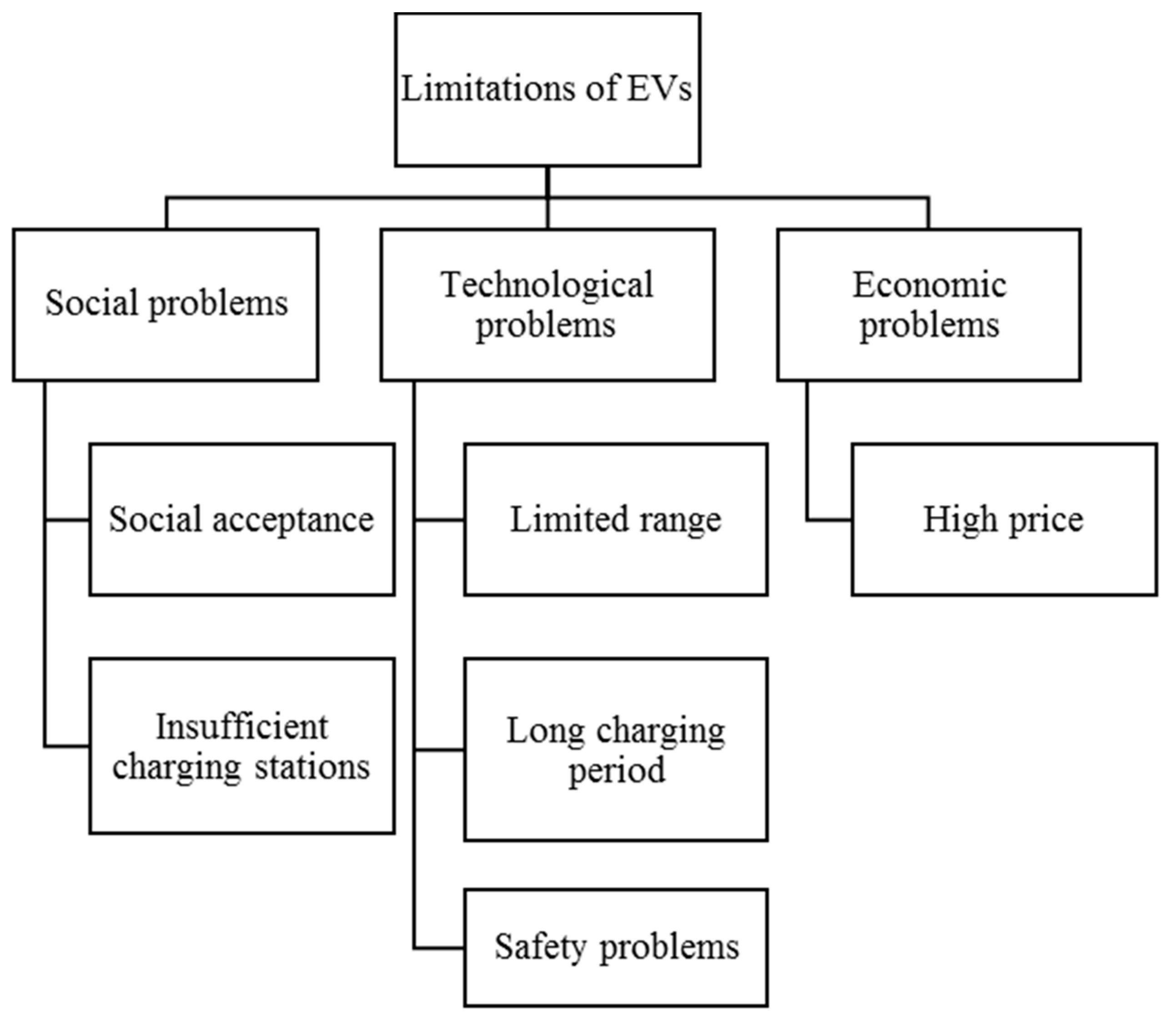
9. Barriers to EV Adoption
9.1. Technological Problems
9.1.1. Limited Range
9.1.2. Long Charging Period
9.1.3. Safety Concerns
9.2. Social Problems
9.2.1. Social Acceptance
9.2.2. Insufficient Charging Stations
9.3. Economic Problems
High Price
10. Optimization Techniques
11. Control Algorithms
12. Global EV Sales Figures
13. Trends and Future Developments
14. Outcomes
- EVs can be classified as BEV, HEV, PHEV, and FCEV. BEVs and PHEVs are the current trends. FCEVs can become mainstream in future. Low cost fuel cells are the main prerequisite for that and there is need of more research to make that happen. There are also strong chances for BEVs to be the market dominators with ample advancement in key technologies; energy storage and charging systems being two main factors. Currently FCVs appear to have little chance to become ubiquitous, these may find popularity in niche markets, for example, the military and utility vehicles.
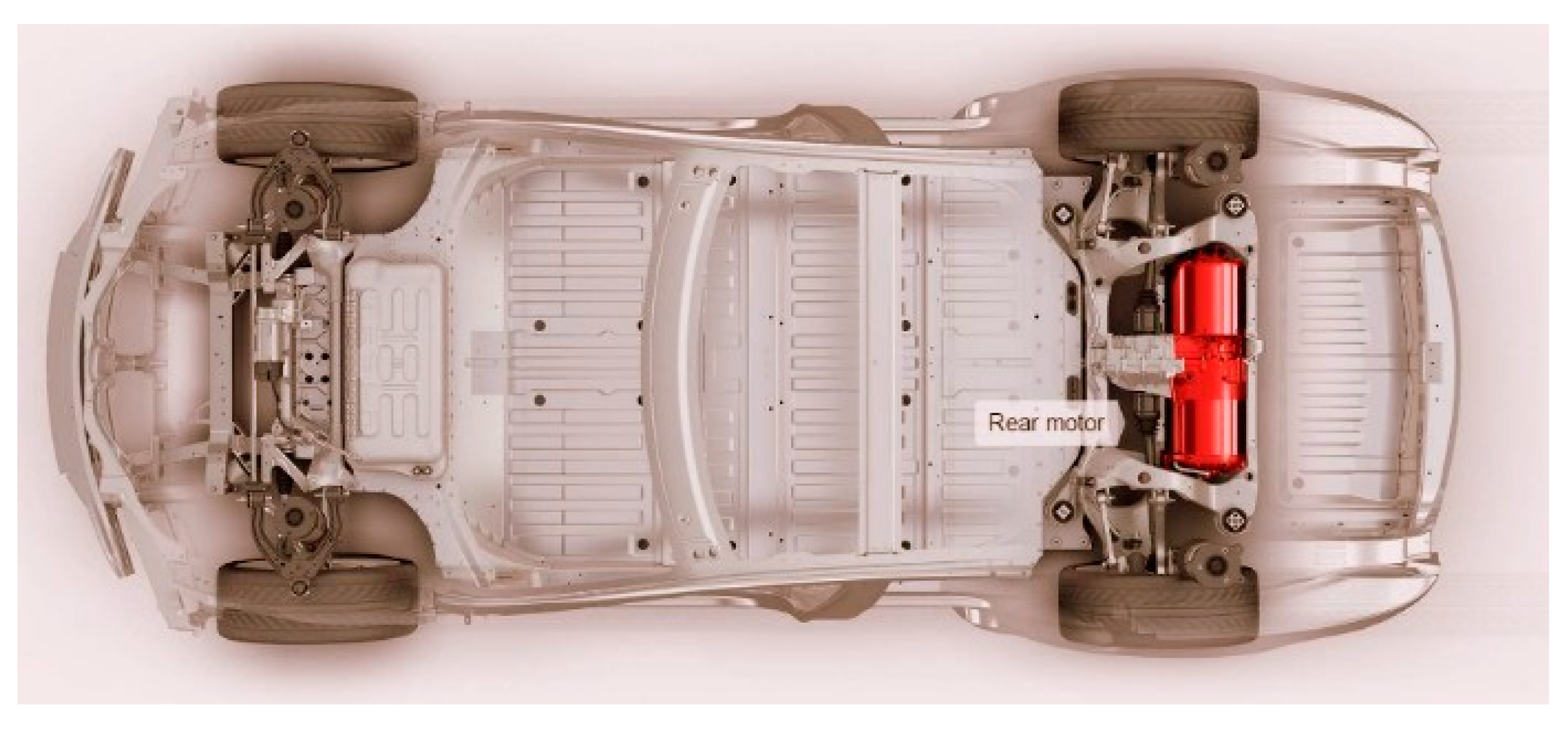
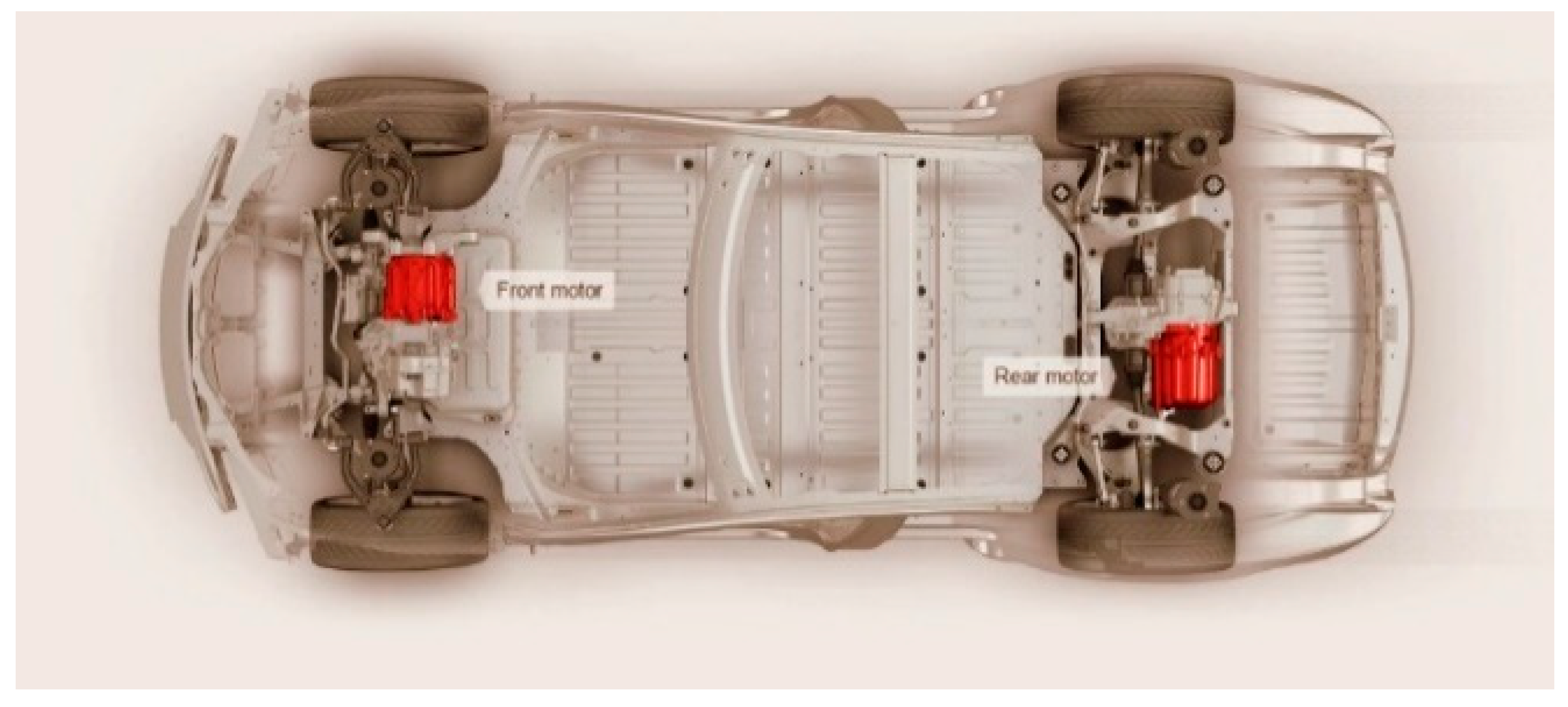
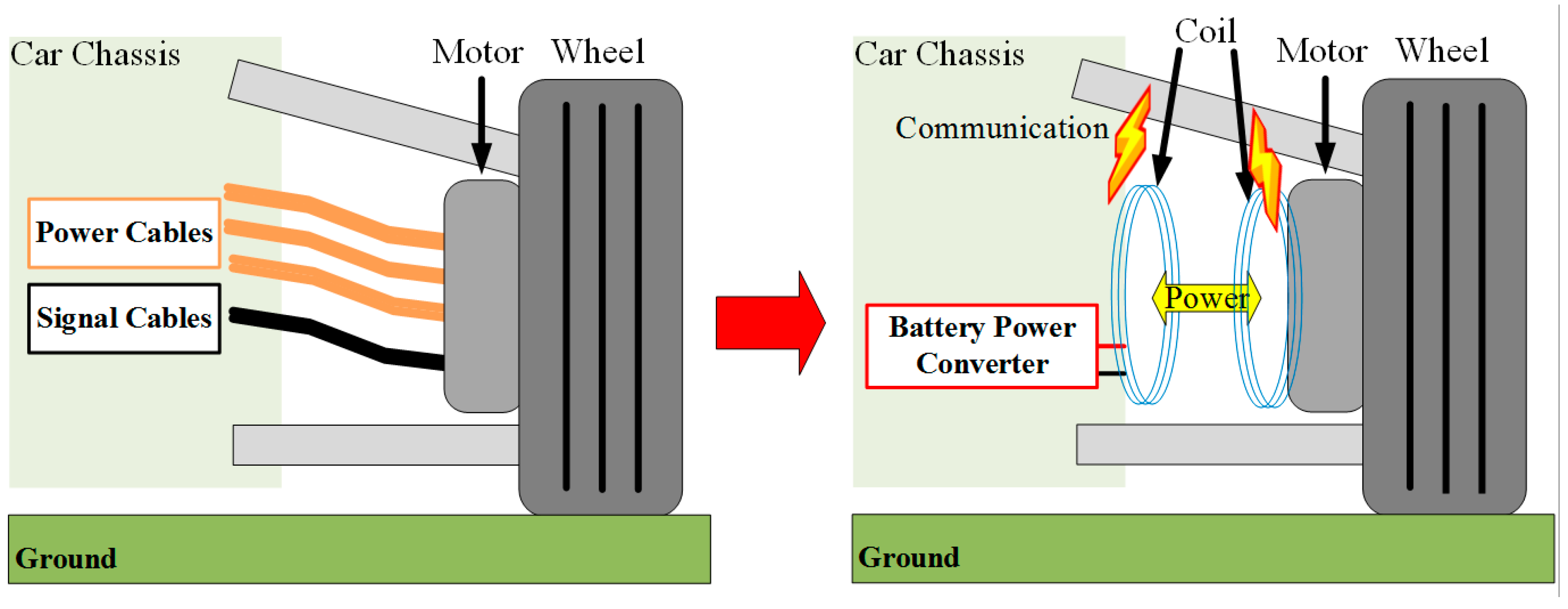
- EVs can be front wheel drive, rear wheel drive, even all-wheel drive. Different configurations are applied depending on the application of the vehicle. The motor can also be placed inside the wheel of the vehicle which offers distinct advantages. This configuration is not commercially abundant now, and has scopes for more study to turn it into a viable product.
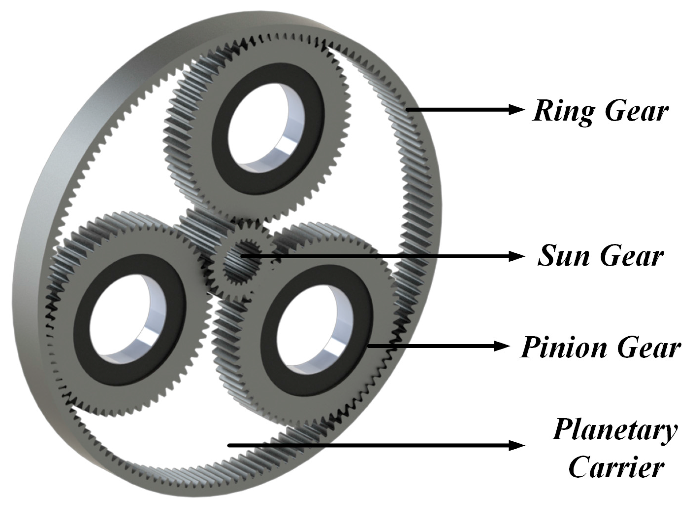
- The main HEV configurations are classified as series, parallel, and series-parallel. Current vehicles are using the series-parallel system mainly as it can operate in both battery-only and ICE-only modes, providing more efficiency and less fuel consumption than the other two systems.
- Currently EVs use batteries as the main energy source. Battery technology has gone through significant changes, the lead-acid technology is long gone, as is the NiMH type. Li-ion batteries are currently in use, but even they are not capable enough to provide the amount of energy required to appease the consumers suffering from ‘range anxiety’ in most cases. Therefore the main focus of research in this area has to be creating batteries with more capacity, and also with better power densities. Metal-air batteries can be the direction where the EV makers will head towards. Lithium-sulfur battery and advanced rechargeable zinc batteries also have potential provide better EVs. Nevertheless, low cost energy sources will be sought after always as ESS cost is one of the major contributors to high EV cost.
- Ultracapacitors are considered as auxiliary power sources because of their high power densities. If coupled with batteries, ultracapacitors produce a hybrid ESS that can satisfy some requirements demanded from an ideal source. Flywheels are also being used, especially because of their compact build and capability to store and discharge power on demand. Fuel cells can also be used more in the future if FCVs gain popularity.
- Different types of motors can be employed for EV use. The prominent ones can be listed as induction motor, permanent magnet synchronous motor, and synchronous reluctance motor. Induction motors are being extensively these days, they can also dominate in future because of their independence on rare-earth material permanent magnets.
- EVs can be charged with AC or DC supply. There are different voltage levels and they are designated accordingly. Higher voltage levels provide faster charging. DC supplies negate the need of rectification from AC, which reduces delay and loss. However, with increased voltage level, the pressure on the grid increases and can give rise to harmonics as well as voltage imbalance in an unsupervised system. Therefore, there are ample chances of research in the field of mitigating the problems associated with high-voltage charging.
- Two charger configurations are mainly available now: CCS and CHAdeMO. These two systems are not compatible with each other and each has a number of automakers supporting them. Tesla also brought their own ‘supercharger’ system, which provides a faster charging facility. It is not possible to determine now which one of these will prevail, or if both will co-exist, technical study is needed to find out the most useful one of these configurations or ways to make them compatible with each other.
- Whatever the charging system is, the charging time is still very long. This is a major disadvantage that is thwarting the growth of the EV market. Extensive research is needed in this sector to provide better technologies that can provide much faster charging and can be compatible with the small time required to refill an ICE vehicle. Wireless charging is also something in need of research. With all the conveniences it promises, it is still not in a viable form to commercialize.
- EV impacts the environment, power system, and economy alongside the transportation sector. It shows promises to reduce the GHG emissions as well as efficient and economical transport solutions. At the same time, it can cause serious problems in the power system including voltage instability, harmonics, and voltage sag, but these shortcomings may be short-lived if smart grid technologies are employed. There are prospects of research in the areas of V2G, smart metering, integration of RES, and system stability associated with EV penetration.
- EVs employ different techniques to reduce energy loss and increase efficiency. Reducing the drag coefficient, weight reduction, regenerative braking, and intelligent energy management are some of these optimization techniques. Further research directions can be better aerodynamic body designs, new materials with less weight and desired strength, ways to generate and restore the lost energy.
- Different control algorithms have been developed for driving assist, energy management, and charging. There is lots of room left for more research into charging and energy management algorithms. With increased EV penetration in the future, demands for efficient algorithms are bound to increase.
15. Conclusions
Acknowledgments
Author Contributions
Conflicts of Interest
References
- Yong, J.Y.; Ramachandaramurthy, V.K.; Tan, K.M.; Mithulananthan, N. A review on the state-of-the-art technologies of electric vehicle, its impacts and prospects. Renew. Sustain. Energy Rev. 2015, 49, 365–385. [Google Scholar] [CrossRef]
- Camacho, O.M.F.; Nørgård, P.B.; Rao, N.; Mihet-Popa, L. Electrical Vehicle Batteries Testing in a Distribution Network using Sustainable Energy. IEEE Trans. Smart Grid 2014, 5, 1033–1042. [Google Scholar] [CrossRef]
- Camacho, O.M.F.; Mihet-Popa, L. Fast Charging and Smart Charging Tests for Electric Vehicles Batteries using Renewable Energy. Oil Gas Sci. Technol. 2016, 71, 13–25. [Google Scholar] [CrossRef]
- Chan, C.C. The state of the art of electric and hybrid vehicles. Proc. IEEE 2002, 90, 247–275. [Google Scholar] [CrossRef]
- Grunditz, E.A.; Thiringer, T. Performance Analysis of Current BEVs Based on a Comprehensive Review of Specifications. IEEE Trans. Transp. Electr. 2016, 2, 270–289. [Google Scholar] [CrossRef]
- SAE International. SAE Electric Vehicle and Plug-in Hybrid Electric Vehicle Conductive Charge Coupler. In SAE Standard J1772; Society of Automotive Engineers (SAE): Warrendale, PA, USA, 2010. [Google Scholar]
- Yilmaz, M.; Krein, P.T. Review of battery charger topologies, charging power levels, and infrastructure for plug-in electric and hybrid vehicles. IEEE Trans. Power Electr. 2013, 28, 2151–2169. [Google Scholar] [CrossRef]
- Bayindir, K.Ç.; Gözüküçük, M.A.; Teke, A. A comprehensive overview of hybrid electric vehicle: Powertrain configurations, powertrain control techniques and electronic control units. Energy Convers. Manag. 2011, 52, 1305–1313. [Google Scholar] [CrossRef]
- Marchesoni, M.; Vacca, C. New DC–DC converter for energy storage system interfacing in fuel cell hybrid electric vehicles. IEEE Trans. Power Electron. 2007, 22, 301–308. [Google Scholar] [CrossRef]
- Schaltz, E.; Khaligh, A.; Rasmussen, P.O. Influence of battery/ultracapacitor energy-storage sizing on battery lifetime in a fuel cell hybrid electric vehicle. IEEE Trans. Veh. Technol. 2009, 58, 3882–3891. [Google Scholar] [CrossRef]
- Kramer, B.; Chakraborty, S.; Kroposki, B. A review of plug-in vehicles and vehicle-to-grid capability. In Proceedings of the 34th IEEE Industrial Electronics Annual Conference, Orlando, FL, USA, 10–13 November 2008; pp. 2278–2283. [Google Scholar]
- Williamson, S.S. Electric drive train efficiency analysis based on varied energy storage system usage for plug-in hybrid electric vehicle applications. In Proceedings of the IEEE Power Electronics Specialists Conference, Orlando, FL, USA, 17–21 June 2007; pp. 1515–1520. [Google Scholar]
- Wirasingha, S.G.; Schofield, N.; Emadi, A. Plug-in hybrid electric vehicle developments in the US: Trends, barriers, and economic feasibility. In Proceedings of the IEEE Vehicle Power and Propulsion Conference, Harbin, China, 3–5 September 2008; pp. 1–8. [Google Scholar]
- Gao, Y.; Ehsani, M. Design and control methodology of plug-in hybrid electric vehicles. IEEE Trans. Ind. Electron. 2010, 57, 633–640. [Google Scholar]
- EG&G Technical Services, Inc. The Fuel Cell Handbook, 6th ed.; U.S. Department of Energy: Morgantown, WV, USA, 2002.
- Miller, J.F.; Webster, C.E.; Tummillo, A.F.; DeLuca, W.H. Testing and evaluation of batteries for a fuel cell powered hybrid bus. In Proceedings of the Energy Conversion Engineering Conference, Honolulu, HI, USA, 27 July–1 August 1997; Volume 2, pp. 894–898. [Google Scholar]
- Rodatz, P.; Garcia, O.; Guzzella, L.; Büchi, F.; Bärtschi, M.; Tsukada, A.; Dietrich, P.; Kötz, R.; Scherer, G.; Wokaun, A. Performance and operational characteristics of a hybrid vehicle powered by fuel cells and supercapacitors. In Proceedings of the SAE 2003 World Congress and Exhibition, Detroit, MI, USA, 3 March 2003; Volume 112, pp. 692–703. [Google Scholar]
- Thounthong, P.; Raël, S.; Davat, B. Utilizing fuel cell and supercapacitors for automotive hybrid electrical system. In Proceedings of the Applied Power Electronics Conference and Exposition, Austin, TX, USA, 6–10 March 2005; Volume 1, pp. 90–96. [Google Scholar]
- Why the Automotive Future Will Be Dominated by Fuel Cells—IEEE Spectrum. Available online: http://spectrum.ieee.org/green-tech/fuel-cells/why-the-automotive-future-will-be-dominated-by-fuel-cells (accessed on 8 May 2017).
- Rose, R. Questions and Answers about Hydrogen and Fuel Cells; Report Style; U.S. Department of Energy: Washington, DC, USA, 2005.
- U.S. Climate Technology Program: Technology Options for the Near and Long Term (Report Style); U.S. Climate Change Technology Program: Washington, DC, USA, 2005.
- Thomas, C.E. Fuel cell and battery electric vehicles compared. Int. J. Hydrogen Energy 2009, 34, 6005–6020. [Google Scholar] [CrossRef]
- Rajashekara, K. Present status and future trends in electric vehicle propulsion technologies. IEEE J. Emerg. Sel. Top. Power Electron. 2013, 1, 3–10. [Google Scholar] [CrossRef]
- Model S | Tesla. Available online: https://www.tesla.com/models (accessed on 8 May 2017).
- Tahami, F.; Kazemi, R.; Farhanghi, S. A novel driver assist stability system for all-wheel-drive electric vehicles. IEEE Trans. Veh. Technol. 2003, 52, 683–692. [Google Scholar] [CrossRef]
- Sato, M.; Yamamoto, G.; Gunji, D.; Imura, T.; Fujimoto, H. Development of Wireless In-Wheel Motor Using Magnetic Resonance Coupling. IEEE Trans. Power Electron. 2016, 31, 5270–5278. [Google Scholar] [CrossRef]
- Kurs, A.; Karalis, A.; Moffatt, R.; Joannopoulos, J.D.; Fisher, P.; Soljačić, M. Wireless power transfer via strongly coupled magnetic resonances. Science 2007, 317, 83–86. [Google Scholar] [CrossRef] [PubMed]
- Imura, I.; Uchida, T.; Hori, Y. Flexibility of contactless power transfer using magnetic resonance coupling to air gap and misalignment for EV. World Electr. Veh. J. 2009, 3, 24–34. [Google Scholar]
- Nakadachi, S.; Mochizuki, S.; Sakaino, S.; Kaneko, Y.; Abe, S.; Yasuda, T. Bidirectional contactless power transfer system expandable from unidirectional system. In Proceedings of the 2013 IEEE Energy Conversion Congress and Exposition, Denver, CO, USA, 15–19 September 2013; pp. 3651–3657. [Google Scholar]
- Gao, Y.; Ehsani, M.; Miller, J.M. Hybrid Electric Vehicle: Overview and State of the Art. In Proceedings of the IEEE International Symposium on Industrial Electronics, Dubrovnik, Croatia, 20‒23 June 2005; pp. 307–316. [Google Scholar]
- Kim, H.; Kum, D. Comprehensive Design Methodology of Input- and Output-Split Hybrid Electric Vehicles: In Search of Optimal Configuration. IEEE/ASME Trans. Mechatron. 2016, 21, 2912–2923. [Google Scholar] [CrossRef]
- Miller, J.M. Hybrid electric vehicle propulsion system architectures of the e-CVT type. IEEE Trans. Power Electron. 2006, 21, 756–767. [Google Scholar] [CrossRef]
- Kim, D.; Hwang, S.; Kim, H. Vehicle Stability Enhancement of Four-Wheel-Drive Hybrid Electric Vehicle Using Rear Motor Control. IEEE Trans. Veh. Technol. 2008, 57, 727–735. [Google Scholar]
- Li, Y.; Yang, J.; Song, J. Nano energy system model and nanoscale effect of graphene battery in renewable energy electric vehicle. Renew. Sustain. Energy Rev. 2017, 69, 652–663. [Google Scholar] [CrossRef]
- Khaligh, A.; Li, Z. Battery, ultracapacitor, fuel cell, and hybrid energy storage systems for electric, hybrid electric, fuel cell, and plug-in hybrid electric vehicles: State of the art. IEEE Trans. Veh. Technol. 2010, 59, 2806–2814. [Google Scholar] [CrossRef]
- Olson, J.B.; Sexton, E.D. Operation of lead–acid batteries for HEV applications. In Proceedings of the 15th Battery Conference on Applications and Advances, Long Beach, CA, USA, 11–14 January 2000; pp. 205–210. [Google Scholar]
- Edwards, D.B.; Kinney, C. Advanced lead acid battery designs for hybrid electric vehicles. In Proceedings of the 16th Battery Conference on Applications and Advances, Long Beach, CA, USA, 12 January 2001; pp. 207–212. [Google Scholar]
- Cooper, A.; Moseley, P. Progress in the development of lead–acid batteries for hybrid electric vehicles. In Proceedings of the IEEE Vehicle Power and Propulsion Conference, Windsor, UK, 6–8 September 2006; pp. 1–6. [Google Scholar]
- Fetcenko, M.A.; Fetcenko, M.A.; Ovshinsky, S.R.; Reichman, B.; Young, K.; Fierro, C.; Koch, J.; Zallen, A.; Mays, W.; Ouchi, T. Recent advances in NiMH battery technology. J. Power Sources 2007, 165, 544–551. [Google Scholar] [CrossRef]
- Li, H.; Liao, C.; Wang, L. Research on state-of-charge estimation of battery pack used on hybrid electric vehicle. In Proceedings of the Asia-Pacific Power and Energy Engineering Conference, Wuhan, China, 27–31 March 2009; pp. 1–4. [Google Scholar]
- Chalk, S.G.; Miller, J.F. Key challenges and recent progress in batteries, fuel cells, and hydrogen storage for clean energy systems. J. Power Sources 2006, 159, 73–80. [Google Scholar] [CrossRef]
- Balch, R.C.; Burke, A.; Frank, A.A. The affect of battery pack technology and size choices on hybrid electric vehicle performance and fuel economy. In Proceedings of the 16th IEEE Annual Battery Conference on Applications and Advances, Long Beach, CA, USA, 12 January 2001; pp. 31–36. [Google Scholar]
- Viera, J.C.; Gonzalez, M.; Anton, J.C.; Campo, J.C.; Ferrero, F.J.; Valledor, M. NiMH vs. NiCd batteries under high charging rates. In Proceedings of the 28th Annual Telecommunications Energy Conference, Providence, RI, USA, 10–14 September 2006; pp. 1–6. [Google Scholar]
- Gao, Y.; Ehsani, M. Investigation of battery technologies for the army’s hybrid vehicle application. In Proceedings of the 56th IEEE Vehicular Technology Conference, Vancouver, BC, Canada, 24–28 September 2002; pp. 1505–1509. [Google Scholar]
- Pilot, C. The Rechargeable Battery Market and Main Trends 2014–2025. Available online: http://www.avicenne.com/pdf/Fort_Lauderdale_Tutorial_C_Pillot_March2015.pdf (accessed on 29 July 2017).
- Williamson, S.S.; Rathore, A.K.; Musavi, F. Industrial electronics for electric transportation: Current state-of-the-art and future challenges. IEEE Trans. Ind. Electron. 2015, 62, 3021–3032. [Google Scholar] [CrossRef]
- Cassani, P.A.; Williamson, S.S. Feasibility analysis of a novel cell equalizer topology for plug-in hybrid electric vehicle energy-storage systems. IEEE Trans. Veh. Technol. 2009, 58, 3938–3946. [Google Scholar] [CrossRef]
- Baughman, A.C.; Ferdowsi, M. Double-tiered switched-capacitor battery charge equalization technique. IEEE Trans. Ind. Electron. 2008, 55, 2277–2285. [Google Scholar] [CrossRef]
- Nishijima, K.; Sakamoto, H.; Harada, K. A PWM controlled simple and high performance battery balancing system. In Proceedings of the IEEE Power Electronics Specialists Conference, Galway, Ireland, 23 June 2000; Volume 1, pp. 517–520. [Google Scholar]
- Cassani, P.A.; Williamson, S.S. Design, testing, and validation of a simplified control scheme for a novel plug-in hybrid electric vehicle battery cell equalizer. IEEE Trans. Ind. Electron. 2010, 57, 3956–3962. [Google Scholar] [CrossRef]
- Lee, Y.S.; Cheng, M.W. Intelligent control battery equalization for series connected lithium-ion battery strings. IEEE Trans. Ind. Electron. 2005, 52, 1297–1307. [Google Scholar] [CrossRef]
- Lee, Y.S.; Cheng, M.W.; Yang, S.C.; Hsu, C.L. Individual cell equalization for series connected lithium-ion batteries. IEICE Trans. Commun. 2006, E89-B, 2596–2607. [Google Scholar] [CrossRef]
- 2017 Nissan LEAF® Electric Car Specs. Available online: https://www.nissanusa.com/electric-cars/leaf/versions-specs/ (accessed on 8 May 2017).
- Model S Specifications | Tesla. Available online: https://www.tesla.com/support/model-s-specifications (accessed on 8 May 2017).
- Why We Still Don’t Have Better Batteries—MIT Technology Review. Available online: https://www.technologyreview.com/s/602245/why-we-still-dont-have-better-batteries/ (accessed on 8 May 2017).
- Ribeiro, P.F.; Johnson, B.K.; Crow, M.L.; Arsoy, A.; Liu, Y. Energy storage systems for advanced power applications. Proc. IEEE 2001, 89, 1744–1756. [Google Scholar] [CrossRef]
- Bartley, T. Ultracapacitors and batteries for energy storage in heavy-duty hybrid-electric vehicles. In Proceedings of the 22nd International Battery Seminar & Exhibit, Fort Lauderdale, FL, USA, 14–17 March 2005. [Google Scholar]
- Gigaom | How Ultracapacitors Work (and Why They Fall Short). Available online: https://gigaom.com/2011/07/12/how-ultracapacitors-work-and-why-they-fall-short/ (accessed on 8 May 2017).
- Singh, A.; Karandikar, P.B. A broad review on desulfation of lead-acid battery for electric hybrid vehicle. Microsyst. Technol. 2017, 23, 1–11. [Google Scholar] [CrossRef]
- Chiu, H.J.; Lin, L.W. A bidirectional DC-DC converter for fuel cell electric vehicle driving system. IEEE Trans. Power Electron. 2006, 21, 950–958. [Google Scholar] [CrossRef]
- Mahlia, T.M.I.; Saktisahdan, T.J.; Jannifar, A.; Hasan, M.H.; Matseelar, H.S.C. A review of available methods and development on energy storage; technology update. Renew. Sustain. Energy Rev. 2014, 33, 532–545. [Google Scholar] [CrossRef]
- Bolund, B.; Bernhoff, H.; Leijon, M. Flywheel energy and power storage systems. Renew. Sustain. Energy Rev. 2007, 11, 235–258. [Google Scholar] [CrossRef]
- Luo, X.; Wang, J.; Dooner, M.; Clarke, J. Overview of current development in electrical energy storage technologies and the application potential in power system operation. Appl. Energy 2015, 137, 511–536. [Google Scholar] [CrossRef]
- Chan, C.C.; Chau, K.T. An overview of power electronics in electric vehicles. IEEE Trans. Ind. Electron. 1997, 44, 3–13. [Google Scholar] [CrossRef]
- Chan, C.C.; Chau, K.T.; Jiang, J.Z.; Xia, W.A.X.W.; Zhu, M.; Zhang, R. Novel permanent magnet motor drives for electric vehicles. IEEE Trans. Ind. Electron. 1996, 43, 331–339. [Google Scholar] [CrossRef]
- Chan, C.C.; Chau, K.T.; Yao, J. Soft-switching vector control for resonant snubber based inverters. In Proceedings of the IEEE International Conference Industrial Electronics, New Orleans, LA, USA, 14 November 1997; pp. 605–610. [Google Scholar]
- Chan, C.C.; Jiang, J.Z.; Chen, G.H.; Chau, K.T. Computer simulation and analysis of a new polyphase multipole motor drive. IEEE Trans. Ind. Electron. 1993, 40, 570–576. [Google Scholar] [CrossRef]
- Chan, C.C.; Jiang, J.Z.; Chen, G.H.; Wang, X.Y.; Chau, K.T. A novel polyphase multipole square-wave permanent magnet motor drive for electric vehicles. IEEE Trans. Ind. Appl. 1994, 30, 1258–1266. [Google Scholar] [CrossRef]
- Chan, C.C.; Jiang, J.Z.; Xia, W.; Chan, K.T. Novel wide range speed control of permanent magnet brushless motor drives. IEEE Trans. Power Electron. 1995, 10, 539–546. [Google Scholar] [CrossRef]
- Jose, C.P.; Meikandasivam, S. A Review on the Trends and Developments in Hybrid Electric Vehicles. In Innovative Design and Development Practices in Aerospace and Automotive Engineering; Springer: Singapore, 2017; pp. 211–229. [Google Scholar]
- Chan, C.C.; Chau, K.T. Morden Elcetric Vehicle Technology; Oxford University Press, Inc.: New York, NY, USA, 2001; pp. 122–133. [Google Scholar]
- Lulhe, A.M.; Date, T.N. A technology review paper for drives used in electrical vehicle (EV) & hybrid electrical vehicles (HEV). In Proceedings of the 2015 International Conference on Control, Instrumentation, Communication and Computational Technologies (ICCICCT), Kumaracoil, India, 18–19 December 2015. [Google Scholar]
- Magnussen, F. On design and analysis of synchronous permanent magnet for field—Weakening operation. Ph.D. Thesis, KTH Royal Institute of Technology, Sweden, 2004. [Google Scholar]
- Model X Specifications | Tesla. Available online: https://www.tesla.com/support/model-x-specifications (accessed on 8 May 2017).
- Yamada, K.; Watanabe, K.; Kodama, T.; Matsuda, I.; Kobayashi, T. An efficiency maximizing induction motor drive system for transmissionless electric vehicle. In Proceedings of the 13th International Electric Vehicle Symposium, Osaka, Japan, 13–16 Octobor 1996; Volume II, pp. 529–536. [Google Scholar]
- Boglietti, A.; Ferraris, P.; Lazzari, M.; Profumo, F. A new design criteria for spindles induction motors controlled by field oriented technique. Electr. Mach. Power Syst. 1993, 21, 171–182. [Google Scholar] [CrossRef]
- Abbasian, M.; Moallem, M.; Fahimi, B. Double-stator switched reluctance machines (DSSRM): Fundamentals and magnetic force analysis. IEEE Trans. Energy Convers. 2010, 25, 589–597. [Google Scholar] [CrossRef]
- Cameron, D.E.; Lang, J.H.; Umans, S.D. The origin and reduction of acoustic noise in doubly salient variable-reluctance motors. IEEE Trans. Ind. Appl. 1992, 28, 1250–1255. [Google Scholar] [CrossRef]
- Chan, C.C.; Jiang, Q.; Zhan, Y.J.; Chau, K.T. A high-performance switched reluctance drive for P-star EV project. In Proceedings of the 13th International Electric Vehicle Symposium, Osaka, Japan, 13–16 Octobor 1996; Volume II, pp. 78–83. [Google Scholar]
- Zhan, Y.J.; Chan, C.C.; Chau, K.T. A novel sliding-mode observer for indirect position sensing of switched reluctance motor drives. IEEE Trans. Ind. Electron. 1999, 46, 390–397. [Google Scholar] [CrossRef]
- Shareef, H.; Islam, M.M.; Mohamed, A. A review of the stage-of-the-art charging technologies, placement methodologies, and impacts of electric vehicles. Renew. Sustain. Energy Rev. 2016, 64, 403–420. [Google Scholar] [CrossRef]
- Yu, X.E.; Xue, Y.; Sirouspour, S.; Emadi, A. Microgrid and transportation electrification: A review. In Proceedings of the 2012 IEEE Transportation Electrification Conference and Expo (ITEC), Dearborn, MI, USA, 18–20 June 2012. [Google Scholar]
- Consumer and Clinical Radiation Protection Bureau; Environmental and Radiation Health Sciences Directorate; Healthy Environments and Consumer Safety Branch; Health Canada. Limits of human exposure to radiofrequency electromagnetic energy in the frequency range from 3 kHz to 300 GHz. Health Can. Saf. Code 2009, 6, 10–11. [Google Scholar]
- IEEE Standard for Safety Levels with Respect to Human Exposure to Radio Frequency Electromagnetic Fields, 3 kHz to 300 GHz; IEEE Std C95.1; IEEE: New York, NY, USA, 1999.
- Ahlbom, A.; Bergqvist, U.; Bernhardt, J.H.; Cesarini, J.P.; Court, L.A.; Grandolfo, M.; Hietanen, M.; McKinlay, A.F.; Repacholi, M.H.; Sliney, D.H. Guidelines: For limiting exposure to time-varying electric, magnetic and electromagnetic fields (up to 300 GHz). Health Phys. 1998, 74, 494–521. [Google Scholar]
- Australian Radiation Protection and Nuclear Safety Agency (ARPANSA). Radiation Protection Standard: Maximum Exposure Levels to Radiofrequency Fields—3 kHz to 300 GHz; Radiation Protection Series Publication No. 3; ARPANSA: Melbourne, Australia, 2002.
- Musavi, F.; Eberle, W. Overview of wireless power transfer technologies for electric vehicle battery charging. IET Power Electron. 2014, 7, 60–66. [Google Scholar] [CrossRef]
- Chademo-Ceritifed Chrager List. Available online: www.chademo.com (accessed on 6 July 2015).
- Supercharger. Available online: www.chademo.com (accessed on 7 July 2015).
- International Electrotechnical Commission. Standard IEC 62196—Plugs, Socket-Outlets, Vehicle Couplers and Vehicle Inlets—Conductive Charging of Electric Vehicles; The International Electrotechnical Commission (IEC): Geneva, Switzerland, 2003. [Google Scholar]
- Onar, O.C.; Kobayashi, J.; Khaligh, A. A Fully Directional Universal Power Electronic Interface for EV, HEV, and PHEV Applications. IEEE Trans. Power Electron. 2013, 28, 5489–5498. [Google Scholar] [CrossRef]
- Bose, B.K. Power electronics—A technology review. Proc. IEEE 1992, 80, 1303–1334. [Google Scholar] [CrossRef]
- Yaramasu, V.; Wu, B.; Sen, P.C.; Kouro, S.; Narimani, M. High-power wind energy conversion systems: State-of-the-art and emerging technologies. Proc. IEEE 2015, 103, 740–788. [Google Scholar] [CrossRef]
- Kok, D.; Morris, A.; Knowles, M. Novel EV drive train topology—A review of the current topologies and proposal for a model for improved drivability. In Proceedings of the 2013 15th European Conference on Power Electronics and Applications (EPE), Lille, France, 2–6 September 2013. [Google Scholar]
- Hegazy, O.; Van Mierlo, J.; Lataire, P. Analysis, control and comparison of DC/DC boost converter topologies for fuel cell hybrid electric vehicle applications. In Proceedings of the 14th European Conference on Power Electronics and Applications (EPE 2011), Birmingham, UK, 30 August–1 September 2011. [Google Scholar]
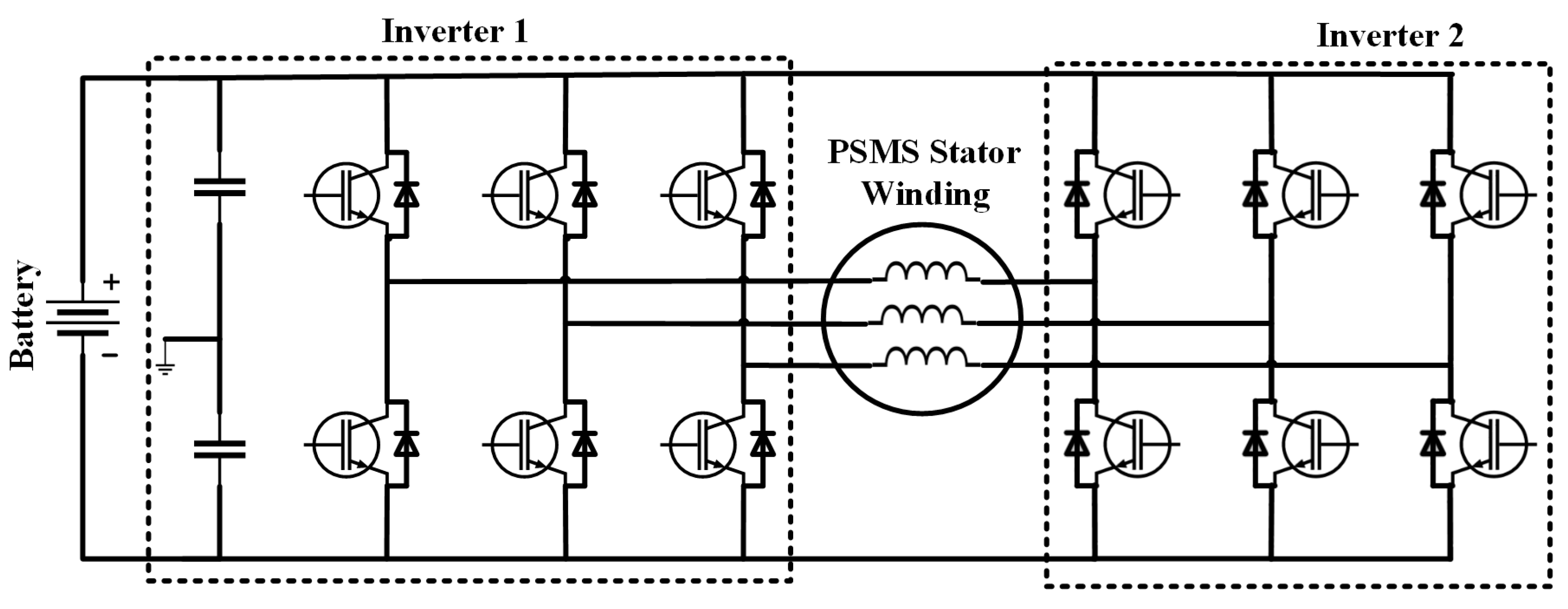
- Hong, J.; Lee, H.; Nam, K. Charging Method for the Secondary Battery in Dual-Inverter Drive Systems for Electric Vehicles. IEEE Trans. Power Electron. 2015, 30, 909–921. [Google Scholar] [CrossRef]
- Sangdehi, S.M.M.; Hamidifar, S.; Kar, N.C. A novel bidirectional DC/AC stacked matrix converter design for electrified vehicle applications. IEEE Trans. Veh. Technol. 2014, 63, 3038–3050. [Google Scholar] [CrossRef]
- Kim, Y.J.; Lee, J.Y. Full-Bridge+ SRT Hybrid DC/DC Converter for a 6.6-kW EV On-Board Charger. IEEE Trans. Veh. Technol. 2016, 65, 4419–4428. [Google Scholar] [CrossRef]
- Kimura, S.; Itoh, Y.; Martinez, W.; Yamamoto, M.; Imaoka, J. Downsizing Effects of Integrated Magnetic Components in High Power Density DC–DC Converters for EV and HEV Applications. IEEE Trans. Ind. Appl. 2016, 52, 3294–3305. [Google Scholar] [CrossRef]
- Schroeder, J.C.; Fuchs, F.W. Detailed Characterization of Coupled Inductors in Interleaved Converters Regarding the Demand for Additional Filtering. In Proceedings of the 2012 IEEE Energy Energy Conversion Congress and Exposition (ECCE), Raleigh, NC, USA, 15–20 September 2012; pp. 759–766. [Google Scholar]
- Imaoka, J.; Yamamoto, M.; Nakamura, Y.; Kawashima, T. Analysis of output capacitor voltage ripple in multi-phase transformer-linked boost chopper circuit. IEEE J. Ind. Appl. 2013, 2, 252–260. [Google Scholar] [CrossRef]
- Zhu, J.; Pratt, A. Capacitor Ripple Current in an interleaved PFC Converter. IEEE Trans. Power Electron. 2009, 24, 1506–1514. [Google Scholar] [CrossRef]
- Wang, C.; Xu, M.; Lee, F.C.; Lu, B. EMI Study for the Interleaved Multi-Channel PFC. In Proceedings of the IEEE Power Electronics Specialists Conference (PESC), Orlando, FL, USA, 17–21 June 2007; pp. 1336–1342. [Google Scholar]
- O’Loughlin, M. An Interleaved PFC Preregulator for High-Power Converters. Available online: http://www.ti.com/download/trng/docs/seminar/Topic5MO.pdf (accessed on 7 August 2017).
- Balogh, L.; Redl, R. Power-factor correction with interleaved boost converters in continuous-inductor-current mode. In Proceedings of the IEEE Applied Power Electronics Conference and Exposition, San Diego, CA, USA, 7–11 March 1993; pp. 168–174. [Google Scholar]
- Jang, Y.; Jovanovic, M.M. Interleaved boost converter with intrinsic voltage-doubler characteristic for universal-line PFC front end. IEEE Trans. Power Electron. 2007, 22, 1394–1401. [Google Scholar] [CrossRef]
- Kong, P.; Wang, S.; Lee, F.C.; Wang, C. Common-mode EMI study and reduction technique for the interleaved multichannel PFC converter. IEEE Trans. Power Electron. 2008, 23, 2576–2584. [Google Scholar] [CrossRef]
- Gautam, D.S.; Musavi, F.; Eberle, W.; Dunford, W.G. A zero voltage switching full-bridge dc-dc converter with capacitive output filter for a plug-in-hybrid electric vehicle battery charger. In Proceedings of the IEEE Applied Power Electronics Conference and Exposition, Orlando, FL, USA, 5–9 February 2012; pp. 1381–1386. [Google Scholar]
- Musavi, F.; Craciun, M.; Gautam, D.S.; Eberle, W.; Dunford, W.G. An LLC resonant DC-DC Converter for wide output voltage range battery charging applications. IEEE Trans. Power Electron. 2013, 28, 5437–5445. [Google Scholar] [CrossRef]
- Gurkaynak, Y.; Li, Z.; Khaligh, A. A novel grid-tied, solar powered residential home with plug-in hybrid electric vehicle (PHEV) loads. In Proceedings of the 5th Annual IEEE Vehicle Power and Propulsion Conference, Dearborn, MI, USA, 7–10 September 2009; pp. 813–816. [Google Scholar]
- Onar, O. Bi-Directional Rectifier/Inverter and Bi-Directional DC/DC Converters Integration for Plug-in Hybrid Electric Vehicles with Hybrid Battery/Ultra-capacitors Energy Storage Systems; Illinois Institute of Technology: Chicago, IL, USA, 2009. [Google Scholar]
- Rashid, M.H. Power Electronics Handbook: Devices, Circuits and Applications; Elsevier: Amsterdam, The Netherlands, 2010. [Google Scholar]
- Koushki, B.; Safaee, A.; Jain, P.; Bakhshai, A. Review and comparison of bi-directional AC-DC converters with V2G capability for on-board EV and HEV. In Proceedings of the 2014 IEEE Transportation Electrification Conference and Expo (ITEC), Dearborn, MI, USA, 15–18 June 2014. [Google Scholar]
- Yao, L.; Lim, W.H.; Tsai, T.S. A Real-Time Charging Scheme for Demand Response in Electric Vehicle Parking Station. IEEE Trans. Smart Grid 2017, 8, 52–62. [Google Scholar] [CrossRef]
- Kütt, L.; Saarijärvi, E.; Lehtonen, M.; Mõlder, H.; Niitsoo, J. A review of the harmonic and unbalance effects in electrical distribution networks due to EV charging. In Proceedings of the 2013 12th International Conference on Environment and Electrical Engineering (EEEIC), Wroclaw, Poland, 5–8 May 2013. [Google Scholar]
- Richardson, P.; Flynn, D.; Keane, A. Optimal charging of electric vehicles in low-voltage distribution systems. IEEE Trans. Power Syst. 2012, 27, 268–279. [Google Scholar] [CrossRef]
- Mwasilu, F.; Justo, J.J.; Kim, E.K.; Do, T.D.; Jung, J.W. Electric vehicles and smart grid interaction: A review on vehicle to grid and renewable energy sources integration. Renew. Sustain. Energy Rev. 2014, 34, 501–516. [Google Scholar] [CrossRef]
- Green, R.C.; Wang, L.; Alam, M. The impact of plug-in hybrid electric vehicles on distribution networks: A review and outlook. Renew. Sustain. Energy Rev. 2011, 15, 544–553. [Google Scholar] [CrossRef]
- Qian, K.; Zhou, C.; Allan, M.; Yuan, Y. Modeling of load demand due to EV battery charging in distribution systems. IEEE Trans. Power Syst. 2011, 26, 802–810. [Google Scholar] [CrossRef]
- Geng, B.; Mills, J.K.; Sun, D. Two-stage charging strategy for plug-in electric vehicles at the residential transformer level. IEEE Trans. Smart Grid 2013, 4, 1442–1452. [Google Scholar] [CrossRef]
- Fernandez, L.P.; San Román, T.G.; Cossent, R.; Domingo, C.M.; Frias, P. Assessment of the impact of plug-in electric vehicles on distribution networks. IEEE Trans. Power Syst. 2011, 26, 206–213. [Google Scholar] [CrossRef]
- Gómez, J.C.; Morcos, M.M. Impact of EV battery chargers on the power quality of distribution systems. IEEE Trans. Power Deliv. 2003, 18, 975–981. [Google Scholar] [CrossRef]
- Dharmakeerthi, C.H.; Mithulananthan, N.; Saha, T.K. Impact of electric vehicle fast charging on power system voltage stability. Int. J. Electr. Power Energy Syst. 2014, 57, 241–249. [Google Scholar] [CrossRef]
- Mitra, P.; Venayagamoorthy, G.K. Wide area control for improving stability of a power system with plug-in electric vehicles. IET Gener Transm. Distrib. 2010, 4, 1151–1163. [Google Scholar] [CrossRef]
- Rajakaruna, S.; Shahnia, F.; Ghosh, A. Plug in Electric Vehicles in Smart Grids, 1st ed.; Springer Science and Business Media Singapore Pte Ltd.: Singapore, 2015. [Google Scholar]
- Akhavan-Rezai, E.; Shaaban, M.F.; El-Saadany, E.F.; Zidan, A. Uncoordinated charging impacts of electric vehicles on electric distribution grids: Normal and fast charging comparison. In Proceedings of the IEEE Power and Energy Society General Meeting, San Diego, CA, USA, 22–26 July 2012; pp. 1–7. [Google Scholar]
- Jiang, C.; Torquato, R.; Salles, D.; Xu, W. Method to assess the power-quality impact of plug-in electric vehicles. IEEE Trans. Power Deliv. 2014, 29, 958–965. [Google Scholar]
- Desmet, J.J.M.; Sweertvaegher, I.; Vanalme, G.; Stockman, K.; Belmans, R.J.M. Analysis of the neutral conductor current in a three- phase supplied network with nonlinear single-phase loads. IEEE Trans. Ind. Appl. 2003, 39, 587–593. [Google Scholar] [CrossRef]
- Nguyen, V.L.; Tuan, T.Q.; Bacha, S. Harmonic distortion mitigation for electric vehicle fast charging systems. In Proceedings of the 2013 IEEE Grenoble PowerTech (POWERTECH), Grenoble, France, 16–20 June 2013; pp. 1–6. [Google Scholar]
- Melo, N.; Mira, F.; De Almeida, A.; Delgado, J. Integration of PEV in Portuguese distribution grid: Analysis of harmonic current emissions in charging points. In Proceedings of the International Conference on Electrical Power Quality and Utilization, Lisbon, Portugal, 17–19 October 2011; pp. 791–796. [Google Scholar]
- Zamri, M.; Wanik, C.; Siam, M.F.; Ayob, A.; Mohamed, A.; Hanifahazit, A.; Sulaiman, S.; Ali, M.A.M.; Hussein, Z.F.; MatHussin, A.K. Harmonic measurement and analysis during electric vehicle charging. Engineering 2013, 5, 215–220. [Google Scholar]
- Bentley, E.C.; Suwanapingkarl, P.; Weerasinghe, S.; Jiang, T.; Putrus, G.A.; Johnston, D. The interactive effects of multiple EV chargers within a distribution network. In Proceedings of the IEEE Vehicle Power and Propulsion Conference (VPPC), Lille, France, 1–3 September 2010; pp. 1–6. [Google Scholar]
- Staats, P.T.; Grady, W.M.; Arapostathis, A.; Thallam, R.S. A statistical analysis of the effect of electric vehicle battery charging on distribution system harmonic voltages. IEEE Trans. Power Deliv. 1998, 13, 640–646. [Google Scholar] [CrossRef]
- Balcells, J.; García, J. Impact of plug-in electric vehicles on the supply grid. In Proceedings of the IEEE Vehicle Power and Propulsion Conference (VPPC), Lille, France, 1–3 September 2010; pp. 1–4. [Google Scholar]
- Lee, S.J.; Kim, J.H.; Kim, D.U.; Go, H.S.; Kim, C.H.; Kim, E.S.; Kim, S.K. Evaluation of voltage sag and unbalance due to the system connection of electric vehicles on distribution system. J. Electr. Eng. Technol. 2014, 9, 452–460. [Google Scholar] [CrossRef]
- Tie, C.H.; Gan, C.K.; Ibrahim, K.A. The impact of electric vehicle charging on a residential low voltage distribution network in Malaysia. In Proceedings of the 2014 IEEE Innovative Smart Grid Technologies—Asia (ISGT Asia), Kuala Lumpur, Malaysia, 20–23 May 2014; pp. 272–277. [Google Scholar]
- Leemput, N.; Geth, F.; Van Roy, J.; Delnooz, A.; Buscher, J.; Driesen, J. Impact of electric vehicle on board single-phase charging strategies on a Flemish residential grid. IEEE Trans. Smart Grid 2014, 5, 1815–1822. [Google Scholar] [CrossRef]
- Masoum, M.A.S.; Moses, P.S.; Deilami, S. Load management in smart grids considering harmonic distortion and transformer derating. In Proceedings of the IEEE Innovative Smart Grid Technologies Europe (ISGT Europe), Gaithersburg, MD, USA, 19–21 January 2010; pp. 1–7. [Google Scholar]
- Nyns, K.C.; Haesen, E.; Driesen, J. The impact of charging plug-in hybrid electric vehicles on a residential distribution grid. IEEE Trans. Power Syst. 2010, 25, 371–380. [Google Scholar] [CrossRef]
- Deilami, S.; Masoum, A.S.; Moses, P.S.; Masoum, M.A.S. Real-time coordination of plug-in electric vehicle charging in smart grids to minimize power losses and improve voltage profile. IEEE Trans. Smart Grid 2011, 2, 456–467. [Google Scholar] [CrossRef]
- Sortomme, E.; Hindi, E.M.M.; MacPherson, S.D.J.; Venkata, S.S. Coordinated charging of plug-in hybrid electric vehicles to minimize distribution system losses. IEEE Trans. Smart Grid 2011, 2, 198–205. [Google Scholar] [CrossRef]
- Sadeghi-Barzani, P.; Rajabi-Ghahnavieh, A.; Kazemi-Karegar, H. Optimal fast charging station placing and sizing. Appl. Energy 2014, 125, 289–299. [Google Scholar] [CrossRef]
- Qian, K.; Zhou, C.; Yuan, Y. Impacts of high penetration level of fully electric vehicles charging loads on the thermal ageing of power transformers. Int. J. Electr. Power Energy Syst. 2015, 65, 102–112. [Google Scholar] [CrossRef]
- Razeghi, G.; Zhang, L.; Brown, T.; Samuelsen, S. Impacts of plug-in hybrid electric vehicles on a residential transformer using stochastic and empirical analysis. J. Power Sources 2014, 252, 277–285. [Google Scholar] [CrossRef]
- Elnozahy, M.S.; Salama, M.M. A comprehensive study of the impacts of PHEVs on residential distribution networks. IEEE Trans. Sustain. Energy 2014, 5, 332–342. [Google Scholar] [CrossRef]
- Sortomme, E.; El-Sharkawi, M.A. Optimal charging strategies for unidirectional vehicle-to-grid. IEEE Trans. Smart Grid 2011, 2, 131–138. [Google Scholar] [CrossRef]
- Clement-Nyns, K.; Haesen, E.; Driesen, J. The impact of vehicle-to-grid on the distribution grid. Electr. Power Syst. Res. 2011, 81, 185–192. [Google Scholar] [CrossRef]
- Tulpule, P.; Marano, V.; Yurkovich, S.; Rizzoni, G. Economic and environmental impacts of a PV powered workplace parking garage charging station. Appl. Energy 2013, 108, 323–332. [Google Scholar] [CrossRef]
- Birnie, D.P. Solar-to-vehicle (S2V) systems for powering commuters of the future. J. Power Sources 2009, 186, 539–542. [Google Scholar] [CrossRef]
- Derakhshandeh, S.Y.; Masoum, A.S.; Deilami, S.; Masoum, M.A.; Golshan, M.H. Coordination of generation scheduling with PEVs charging in industrial microgrids. IEEE Trans. Power Syst. 2013, 28, 3451–3461. [Google Scholar] [CrossRef]
- Pillai, R.J.; Heussen, K.; Østergaard, P.A. Comparative analysis of hourly and dynamic power balancing models for validating future energy scenarios. Energy 2011, 36, 3233–3243. [Google Scholar] [CrossRef]
- Borba, B.S.M.; Szklo, A.; Schaeffer, R. Plug-in hybrid electric vehicles as a way to maximize the integration of variable renewable energy in power systems: The case of wind generation in northeastern Brazil. Energy 2012, 37, 469–481. [Google Scholar] [CrossRef]
- Wu, T.; Yang, Q.; Bao, Z.; Yan, W. Coordinated energy dispatching in microgrid with wind power generation and plug-in electric vehicles. IEEE Trans. Smart Grid 2013, 4, 1453–1463. [Google Scholar] [CrossRef]
- Liu, C.; Wang, J.; Botterud, A.; Zhou, Y.; Vyas, A. Assessment of impacts of PHEV charging patterns on wind-thermal scheduling by stochastic unit commitment. IEEE Trans. Smart Grid 2012, 3, 675–683. [Google Scholar] [CrossRef]
- Ma, H.; Balthser, F.; Tait, N.; Riera-Palou, X.; Harrison, A. A new comparison between the life cycle greenhouse gas emissions of battery electric vehicles and internal combustion vehicles. Energy Policy 2012, 44, 160–173. [Google Scholar] [CrossRef]
- Sioshansi, R.; Miller, J. Plug-in hybrid electric vehicles can be clean and economical in dirty power systems. Energy Policy 2011, 39, 6151–6161. [Google Scholar] [CrossRef]
- Donateo, T.; Ingrosso, F.; Licci, F.; Laforgia, D. A method to estimate the environmental impact of an electric city car during six months of testing in an Italian city. J. Power Sources 2014, 270, 487–498. [Google Scholar] [CrossRef]
- Onat, N.C.; Kucukvar, M.; Tatari, O. Conventional, hybrid, plug-in hybrid or electric vehicles? State-based comparative carbon and energy footprint analysis in the United States. Appl. Energy 2015, 150, 36–49. [Google Scholar] [CrossRef]
- Jorgensen, K. Technologies for electric, hybrid and hydrogen vehicles: Electricity from renewable energy sources in transport. Util. Policy 2008, 16, 72–79. [Google Scholar] [CrossRef]
- Kempton, W.; Letendrem, S. Electric vehicles as a new power source for electric utilities. Transp. Res. Part D 1997, 2, 157–175. [Google Scholar] [CrossRef]
- Peterson, S.; Whitacre, J.; Apt, J. The economics of using plug-in hybrid electric vehicles battery packs for grid storage. J. Power Sources 2010, 195, 2377–2384. [Google Scholar] [CrossRef]
- Sioshansi, R.; Denholm, P. The value of plug-in hybrid electric vehicles as grid resources. Energy J. 2010, 31, 1–16. [Google Scholar] [CrossRef]
- Formula, E. Available online: http://www.fiaformulae.com/en (accessed on 8 May 2017).
- Hidrue, M.K.; Parsons, G.R.; Kempton, W.; Gardner, M.P. Willingness to pay for electric vehicles and their attributes. Resour. Energy Econ. 2011, 33, 686–705. [Google Scholar] [CrossRef]
- 2017 Bolt EV: All-Electric Vehicle | Chevrolet. Available online: http://www.chevrolet.com/bolt-ev-electric-vehicle.html (accessed on 8 May 2017).
- Hydrogen Fuel Cell Car | Toyota Mirai. Available online: https://ssl.toyota.com/mirai/fcv.html (accessed on 8 May 2017).
- Wolsink, M. The research agenda on social acceptance of distributed generation in smart grids: Renewable as common pool resources. Renew. Sustain. Energy Rev. 2012, 16, 822–835. [Google Scholar] [CrossRef]
- Kang, J.E.; Brown, T.; Recker, W.W.; Samuelsen, G.S. Refueling hydrogen fuel cell vehicles with 68 proposed refueling stations in California: Measuring deviations from daily travel patterns. Int. J. Hydrogen Energy 2014, 39, 3444–3449. [Google Scholar] [CrossRef]
- Tie, S.F.; Tan, C.W. A review of energy sources and energy management system in electric vehicles. Renew. Sustain. Energy Rev. 2013, 20, 82–102. [Google Scholar] [CrossRef]
- Chan, C.C.; Wong, Y.S. Electric vehicles charge forward. IEEE Power Energy Mag. 2004, 2, 24–33. [Google Scholar] [CrossRef]
- Five Slippery Cars Enter a Wind Tunnel, One Slinks Out a Winner. Available online: https://www.tesla.com/sites/default/files/blog_attachments/the-slipperiest-car-on-the-road.pdf (accessed on 8 May 2017).
- Geng, B.; Mills, J.K.; Sun, D. Two-stage energy management control of fuel cell plug-in hybrid electric vehicles considering fuel cell longevity. IEEE Trans. Veh. Technol. 2012, 61, 498–508. [Google Scholar] [CrossRef]
- Murphey, Y.L.; Park, J.; Chen, Z.; Kuang, M.L.; Masrur, M.A.; Phillips, A.M. Intelligent hybrid vehicle power control—Part I: Machine learning of optimal vehicle power. IEEE Trans. Veh. Technol. 2012, 61, 3519–3530. [Google Scholar] [CrossRef]
- Geng, B.; Mills, J.K.; Sun, D. Energy management control of microturbine powered plug-in hybrid electric vehicles using telemetry equivalent consumption minimization strategy. IEEE Trans. Veh. Technol. 2011, 60, 4238–4248. [Google Scholar] [CrossRef]
- Moura, S.J.; Fathy, H.K.; Callaway, D.S.; Stein, J.L. A stochastic optimal control approach for power management in plug-in hybrid electric vehicles. IEEE Trans. Control Syst. Technol. 2011, 19, 545–555. [Google Scholar] [CrossRef]
- Magallan, G.A.; De Angelo, C.H.; Garcia, G.O. Maximization of the traction forces in a 2WD electric vehicle. IEEE Trans. Veh. Technol. 2011, 60, 369–380. [Google Scholar] [CrossRef]
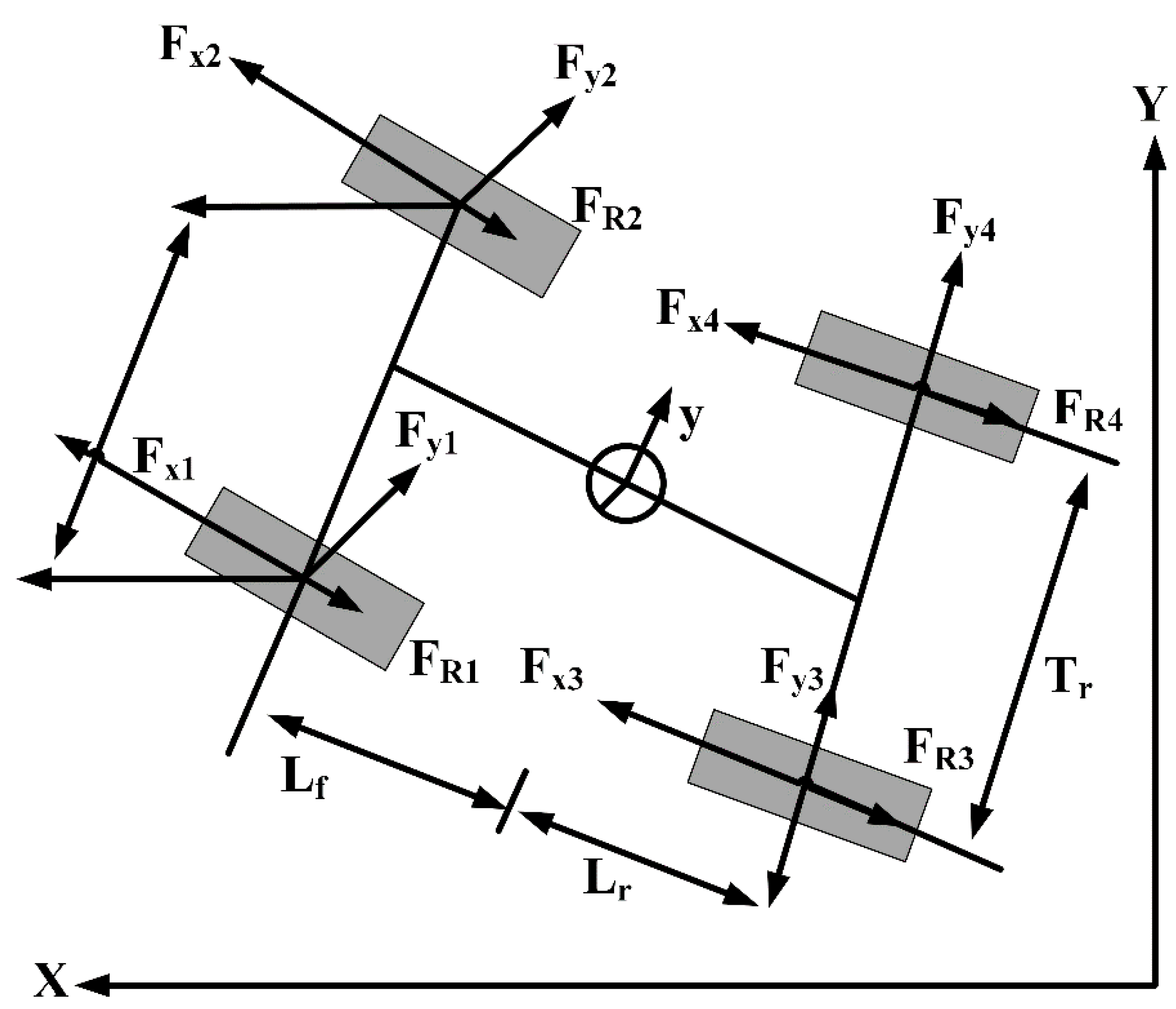
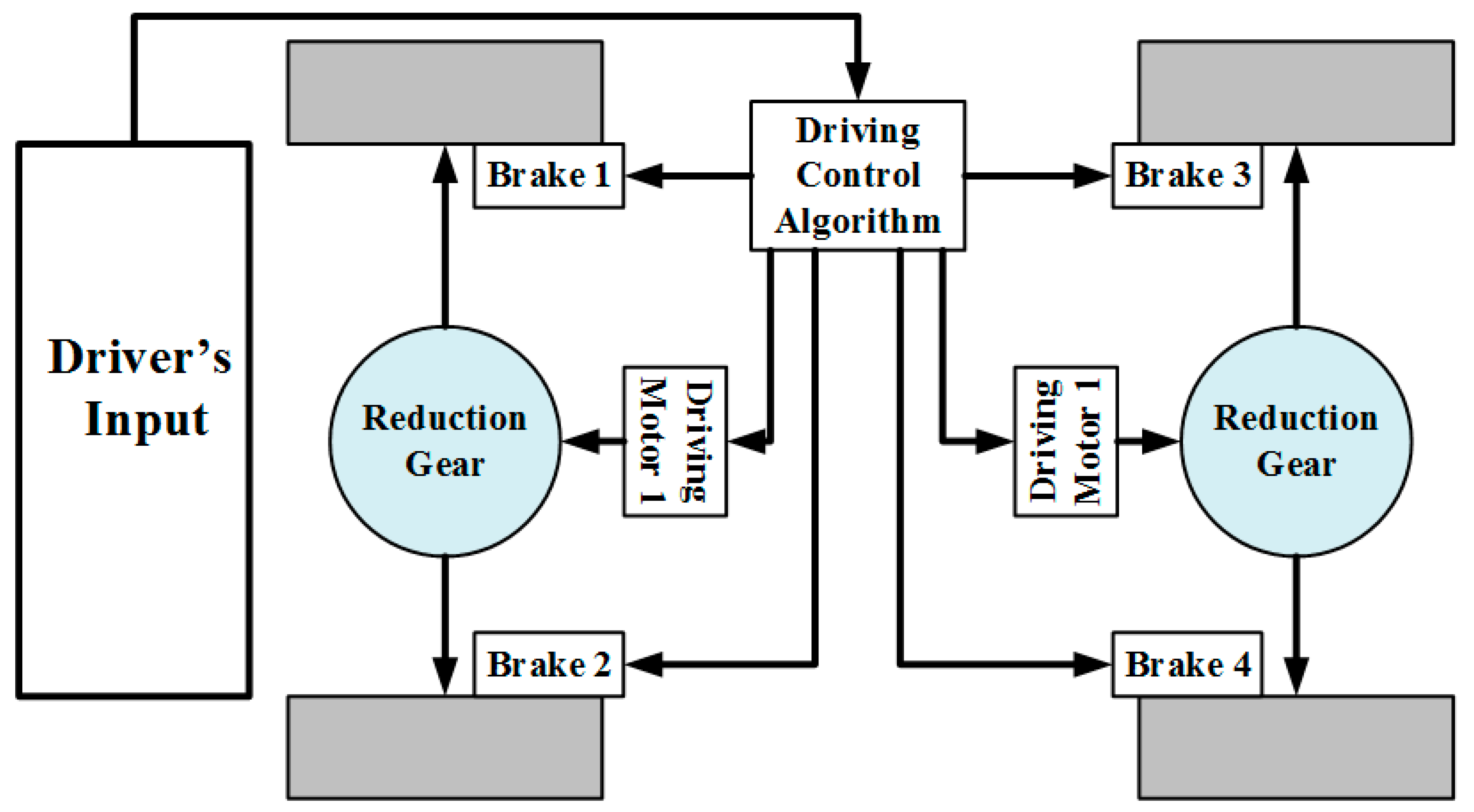
- Kang, J.; Yoo, J.; Yi, K. Driving control algorithm for maneuverability, lateral stability, and rollover prevention of 4WD electric vehicles with independently driven front and rear wheels. IEEE Trans. Veh. Technol. 2011, 60, 2987–3001. [Google Scholar] [CrossRef]
- Wang, J.N.; Wang, Q.N.; Jin, L.Q.; Song, C.X. Independent wheel torque control of 4WD electric vehicle for differential drive assisted steering. Mechatronics 2011, 21, 63–76. [Google Scholar] [CrossRef]
- Nam, K.; Fujimoto, H.; Hori, Y. Lateral stability control of in-wheel-motor-driven electric vehicles based on sideslip angle estimation using lateral tire force sensors. IEEE Trans. Veh. Technol. 2012, 61, 1972–1985. [Google Scholar]
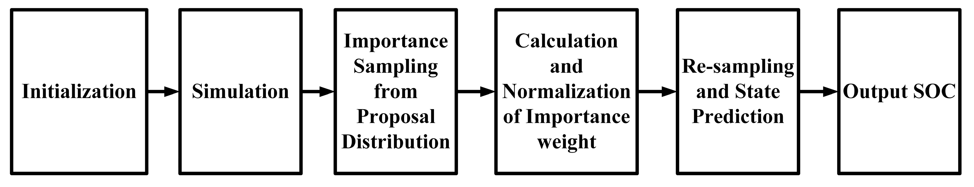
- Zhou, D.; Ravey, A.; Gao, F.; Miraoui, A.; Zhang, K. Online Estimation of Lithium Polymer Batteries State-of-Charge Using Particle Filter-Based Data Fusion with Multimodels Approach. IEEE Trans. Ind. Appl. 2016, 52, 2582–2595. [Google Scholar] [CrossRef]
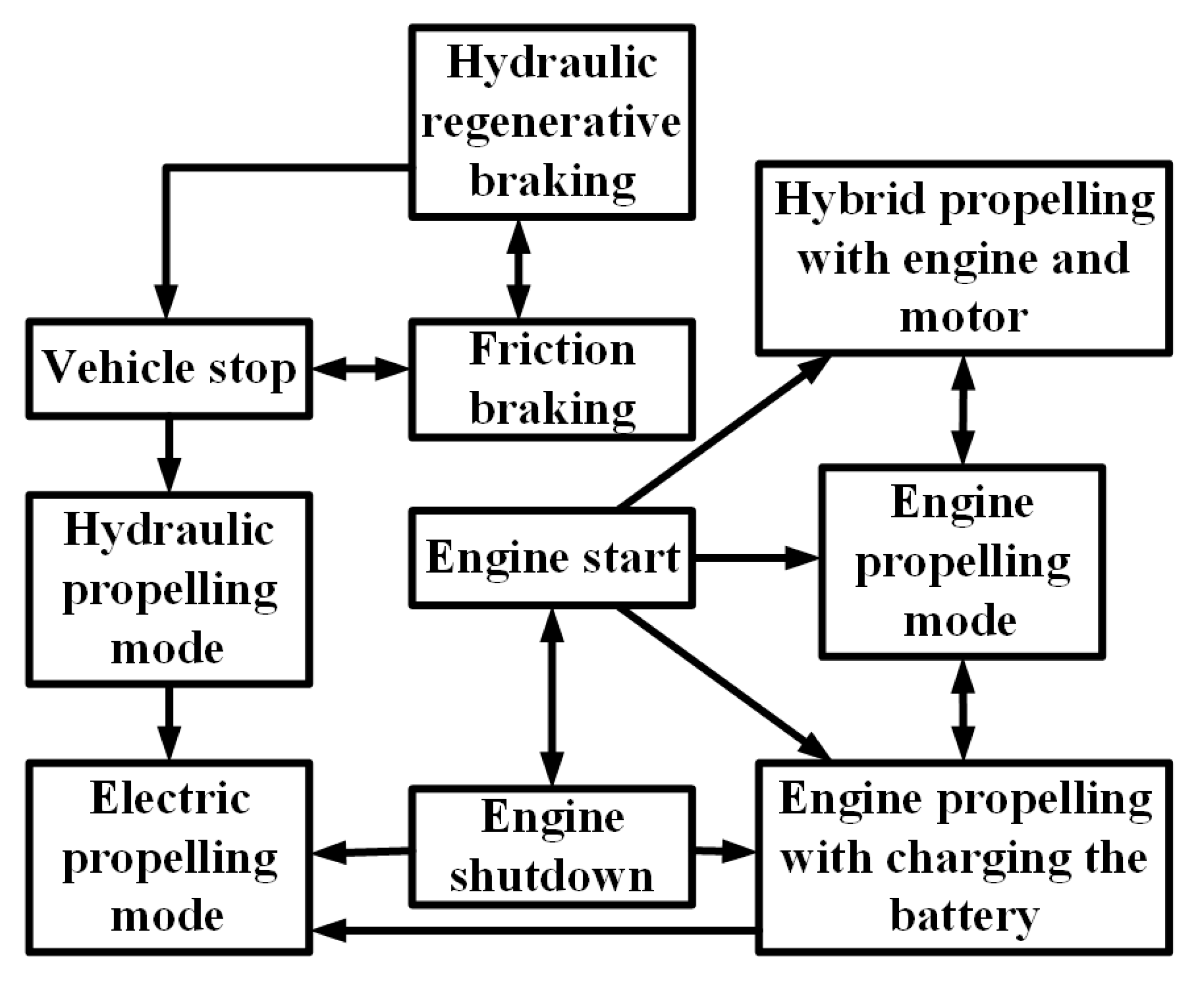
- Hui, S.; Lifu, Y.; Junqing, J.; Yanling, L. Control strategy of hydraulic/electric synergy system in heavy hybrid vehicles. Energy Convers. Manag. 2011, 52, 668–674. [Google Scholar] [CrossRef]
- Chen, Z.; Mi, C.C.; Xiong, R.; Xu, J.; You, C. Energy management of a power-split plug-in hybrid electric vehicle based on genetic algorithm and quadratic programming. J. Power Sources 2014, 248, 416–426. [Google Scholar] [CrossRef]
- Li, S.G.; Sharkh, S.M.; Walsh, F.C.; Zhang, C.N. Energy and battery management of a plug-in series hybrid electric vehicle using fuzzy logic. IEEE Trans. Veh. Technol. 2011, 60, 3571–3585. [Google Scholar] [CrossRef]
- Yuan, Z.; Teng, L.; Fengchun, S.; Peng, H. Comparative study of dynamic programming and Pontryagin’s minimum principle on energy management for a parallel hybrid electric vehicle. Energies 2013, 6, 2305–2318. [Google Scholar] [CrossRef]
- Bernard, J.; Delprat, S.; Guerra, T.M.; Büchi, F.N. Fuel efficient power management strategy for fuel cell hybrid powertrains. Control Eng. Pract. 2010, 18, 408–417. [Google Scholar] [CrossRef]
- Su, W.; Chow, M.Y. Performance evaluation of an EDA-based large-scale plug-in hybrid electric vehicle charging algorithm. IEEE Trans. Smart Grid 2012, 3, 308–315. [Google Scholar] [CrossRef]
- Mohamed, A.; Salehi, V.; Ma, T.; Mohammed, O. Real-time energy management algorithm for plug-in hybrid electric vehicle charging parks involving sustainable energy. IEEE Trans. Sustain. Energy 2014, 5, 577–586. [Google Scholar] [CrossRef]
- Worldwide EV Sales Are on The Move. Available online: http://evercharge.net/blog/infographic-worldwide-ev-sales-are-on-the-move/ (accessed on 8 May 2017).
- China’s Quota Threat Charges Up Electric Car Market | The Daily Star. Available online: http://www.thedailystar.net/business/chinas-quota-threat-charges-electric-car-market-1396066 (accessed on 8 May 2017).
- EV-Volumes—The Electric Vehicle World Sales Database. Available online: http://www.ev-volumes.com/news/china-plug-in-sales-2016-q4-and-full-year/ (accessed on 8 May 2017).
- EV-Volumes—The Electric Vehicle World Sales Database. Available online: http://www.ev-volumes.com/country/total-world-plug-in-vehicle-volumes/ (accessed on 8 May 2017).
- EV-Volumes—The Electric Vehicle World Sales Database. Available online: http://www.ev-volumes.com/country/usa/ (accessed on 8 May 2017).
- EAFO. Available online: http://www.eafo.eu/vehicle-statistics/m1 (accessed on 8 May 2017).
- Hossain, E.; Kabalci, E.; Bayindir, R.; Perez, R. Microgrid testbeds around the world: State of art. Energy Convers. Manag. 2014, 86, 132–153. [Google Scholar] [CrossRef]
- Bayindir, R.; Hossain, E.; Kabalci, E.; Perez, R. A comprehensive study on microgrid technology. Int. J. Renew. Energy Res. 2014, 4, 1094–1107. [Google Scholar]
- eHighway—Siemens Global Website. Available online: https://www.siemens.com/press/en/feature/2015/mobility/2015-06-eHighway.php?content[]=MO (accessed on 8 May 2017).
- Saponara, S.; Petri, E.; Fanucci, L.; Terreni, P. Sensor modeling, low-complexity fusion algorithms, and mixed-signal IC prototyping for gas measures in low-emission vehicles. IEEE Trans. Instrum. Meas. 2011, 60, 372–384. [Google Scholar] [CrossRef]
- Saponara, S.; Pasetti, G.; Costantino, N.; Tinfena, F.; D’Abramo, P.; Fanucci, L. A flexible LED driver for automotive lighting applications: IC design and experimental characterization. IEEE Trans. Power Electron. 2012, 27, 1071–1075. [Google Scholar] [CrossRef]
- Saponara, S.; Pasetti, G.; Tinfena, F.; Fanucci, L.; D’Abramo, P. HV-CMOS design and characterization of a smart rotor coil driver for automotive alternators. IEEE Trans. Ind. Electron. 2013, 60, 2309–2317. [Google Scholar] [CrossRef]
- Baronti, F.; Lazzeri, A.; Roncella, R.; Saletti, R.; Saponara, S. Design and characterization of a robotized gearbox system based on voice coil actuators for a Formula SAE Race Car. IEEE/ASME Trans. Mechatron. 2013, 18, 53–61. [Google Scholar] [CrossRef]
- Costantino, N.; Serventi, R.; Tinfena, F.; D’Abramo, P.; Chassard, P.; Tisserand, P.; Saponara, S.; Fanucci, L. Design and test of an HV-CMOS intelligent power switch with integrated protections and self-diagnostic for harsh automotive applications. IEEE Trans. Ind. Electron. 2011, 58, 2715–2727. [Google Scholar] [CrossRef]
- Saponara, S.; Fanucci, L.; Bernardo, F.; Falciani, A. Predictive diagnosis of high-power transformer faults by networking vibration measuring nodes with integrated signal processing. IEEE Trans. Instrum. Meas. 2016, 65, 1749–1760. [Google Scholar] [CrossRef]
- Abhishek, A.; Karthikeyan, V.; Sanjeevikumar, P.; Rajasekar, S.; Blaabjerg, F.; Asheesh, K.S. Optimal Planning of Electric Vehicle Charging Station at the Distribution System Using Hybrid Optimization Algorithm. Energy 2017, 133, 70–78. [Google Scholar]
- Febin Daya, J.L.; Sanjeevikumar, P.; Blaabjerg, F.; Wheeler, P.; Ojo, O.; Ahmet, H.E. Analysis of Wavelet Controller for Robustness in Electronic Differential of Electric Vehicles—An Investigation and Numerical Implementation. Electr. Power Compon. Syst. 2016, 44, 763–773. [Google Scholar] [CrossRef]
- Febin Daya, J.L.; Sanjeevikumar, P.; Blaabjerg, F.; Wheeler, P.; Ojo, O. Implementation of Wavelet Based Robust Differential Control for Electric Vehicle Application. IEEE Trans. Power Electron. 2015, 30, 6510–6513. [Google Scholar] [CrossRef]
- Sanjeevikumar, P.; Febin Daya, J.L.; Blaabjerg, F.; Mir-Nasiri, N.; Ahmet, H.E. Numerical Implementation of Wavelet and Fuzzy Transform IFOC for Three-Phase Induction Motor. Eng. Sci. Technol. Int. J. 2016, 19, 96–100. [Google Scholar]
- Dragonas, F.A.; Nerrati, G.; Sanjeevikumar, P.; Grandi, G. High-Voltage High-Frequency Arbitrary Waveform Multilevel Generator for DBD Plasma Actuators. IEEE Trans. Ind. Appl. 2015, 51, 3334–3342. [Google Scholar] [CrossRef]
- Mohan, K.; Febin Daya, J.L.; Sanjeevikumar, P.; Mihet-Popa, L. Real-time Analysis of a Modified State Observer for Sensorless Induction Motor Drive used in Electric Vehicle Applications. Energies 2017, 10, 1077. [Google Scholar]


| EV Type | Driving Component | Energy Source | Features | Problems |
|---|---|---|---|---|
| BEV |
|
|
|
|
| HEV |
|
|
|
|
| FCEV |
|
|
|
|
| Advantages | Efficient and optimized power-plant
Possibilities for modular power-plant Optimized drive line Possibility of swift ‘black box’ service exchange Long lifetime Mature technology Fast response Capable of attaining zero emission |
| Limitations | Large traction drive system
Requirement of proper algorithms Multiple energy conversion steps |
| Advantages | Capable of attaining zero emission Economic gain More flexibility |
| Limitations | Expensive Complex control Requirement of proper algorithms Need of high voltage to ensure efficiency |
| Parameters | Parallel HEV | Series HEV |
|---|---|---|
| Voltage | 14 V, 42 V, 144 V, 300 V | 216 V, 274 V, 300 V, 350 V, 550 V, 900 V |
| Power requirement | 3 KW–40 KW | >50 KW |
| Relative gain in fuel economy (%) | 5–40 | >75 |
| Parameters | Mid-Term | Long-Term | |
|---|---|---|---|
| Primary goals | Energy density (C/3 discharge rate) (Wh/L) | 135 | 300 |
| Specific energy (C/3 discharge rate) (Wh/kg) | 80 (Desired: 100) | 200 | |
| Power density (W/l) | 250 | 600 | |
| Specific power (80% DOD/30 s) (W/kg) | 150 (Desired: 200) | 400 | |
| Lifetime (year) | 5 | 10 | |
| Cycle life (80% DOD) (cycles) | 600 | 1000 | |
| Price (USD/kWh) | <150 | <100 | |
| Operating temperature (°C) | −30 to 65 | −40 to 84 | |
| Recharging time (hour) | <6 | 3 to 6 | |
| Fast recharging time (40% to 80% SOC) (hour) | 0.25 | ||
| Secondary goals | Self-discharge (%) | <15 (48 h) | <15 (month) |
| Efficiency (C/3 discharge, 6 h charge) (%) | 75 | 80 | |
| Maintenance | No maintenance | No maintenance | |
| Resistance to abuse | Tolerance | Tolerance | |
| Thermal loss | 3.2 W/kWh | 3.2 W/kWh |
| Battery Type | Components | Advantage | Disadvantage |
|---|---|---|---|
| Lead-acid |
|
|
|
| NiMH (Nickel-Metal Hydride) |
|
|
|
| Li-Ion (Lithium-Ion) |
|
|
|
| Ni-Zn (Nickel-Zinc) |
|
|
|
| Ni-Cd (Nickel-Cadmium) |
|
|
|
| Advantages Over | Lead-Acid | Ni-Cd (Nickel-Cadmium) | NiMH (Nickel–Metal Hydride) | Li-Ion (Lithium-Ion) | |
|---|---|---|---|---|---|
| Conventional | Polymer | ||||
| Lead-acid |
|
|
|
| |
| Ni-Cd (Nickel-Cadmium) |
|
|
|
| |
| NiMH (Nickel-Metal Hydride) |
|
|
|
| |
| Li-Ion (conventional) |
|
|
|
| |
| Li-Ion (polymer) |
|
|
|
| |
| Absolute advantages |
|
|
|
|
|
| Equalizer Type | Advantage | Disadvantage |
|---|---|---|
| Resistive |
|
|
| Capacitive |
|
|
| Basic Inductive |
|
|
| Cuk Inductive |
|
|
| Transformer based Inductive |
|
|
| Multiple transformer based Inductive |
|
|
| Equalizer Type | Equalizer Current | Current Distribution | Current Control | Current Ripple | Manufacture | Cost | Control |
|---|---|---|---|---|---|---|---|
| Resistive | ↓↓ | N/A | ↑ | ↑↑↑ | ↑↑↑ | ↑↑↑ | ↑↑↑ |
| Capacitive | ↓ | ↑ | ↓↓ | ↓↓ | ↑↑ | ↑↑ | ↑↑ |
| Basic Inductive | ↑↑ | ↑ | ↑ | ↑↑ | ↑ | ↓ | ↓ |
| Cuk | ↑↑ | ↑ | ↑ | ↑↑↑ | ↓ | ↓↓ | ↓ |
| Transformer | ↑ | ↑↑↑ | ↓↓ | ↓↓ | ↓↓ | ↓↓ | ↑↑ |
| Model | Total Energy (kWh) | Usable Energy (kWh) | Usable Energy (%) |
|---|---|---|---|
| i3 | 22 | 18.8 | 85 |
| C30 | 24 | 22.7 | 95 |
| B-Class | 36 | 28 | 78 |
| e6 | 61.4 | 57 | 93 |
| RAV4 | 41.8 | 35 | 84 |
| PAFC | AFC | MCFC | SOFC | SPFC | DMFC | |
|---|---|---|---|---|---|---|
| Working temp. (°C) | 150–210 | 60–100 | 600–700 | 900–1000 | 50–100 | 50–100 |
| Power density (W/cm2) | 0.2–0.25 | 0.2–0.3 | 0.1–0.2 | 0.24–0.3 | 0.35–0.6 | 0.04–0.25 |
| Estimated life (kh) | 40 | 10 | 40 | 40 | 40 | 10 |
| Estimated cost (USD/kW) | 1000 | 200 | 1000 | 1500 | 200 | 200 |
| Material | Density (kg/m3) | Tensile Strength (mpa) | Max Energy Density (mj/kg) | Cost (USD/kg) | |
|---|---|---|---|---|---|
| Monolithic material | 4340 steel | 7700 | 1520 | 0.19 | 1 |
| Composites | E-glass | 2000 | 100 | 0.05 | 11 |
| S2-glass | 1920 | 1470 | 0.76 | 24.6 | |
| Carbon T1000 | 1520 | 1950 | 1.28 | 101.8 | |
| Carbon AS4C | 1510 | 1650 | 1.1 | 31.3 | |
| Storage | Energy Density | Power Density |
|---|---|---|
| Battery | High | Low |
| Ultracapacitor | Low | High |
| Fuel cell | High | Low |
| Flywheel | Low | High |
| Storage System | Vehicles Using the System |
|---|---|
| Battery | Tesla Model S, Nissan Leaf |
| Fuel cell + battery | Toyota Mirai, Honda Clarity |
| Flywheel | Porsche 911GT3R Hybrid |
| Motor Type | Power (kW) | Base Speed | Maximum Speed | |
|---|---|---|---|---|
| HEV | BEV | |||
| IM | 57 | 93 | 3000 | 12,000 |
| SRM | 42 | 77 | 2000 | 12,000 |
| BLDC | 75 | 110 | 4000 | 9000 |
| Motor Type | Torque/Volume (Nm/m3) | Torque/Cu Mass (Nm/kg Cu) |
|---|---|---|
| PM motor | 28,860 | 28.7–48 |
| IM | 4170 | 6.6 |
| SRM | 6780 | 6.1 |
| Motor Type | Advantage | Disadvantage | Vehicles Used In |
|---|---|---|---|
| Brushed DC Motor |
|
| Fiat Panda Elettra (Series DC motor), Conceptor G-Van (Separately excited DC motor) |
| Permanent Magnet Brushless DC Motor (BLDC) |
|
| Toyota Prius (2005) |
| Permanent Magnet Synchronous Motor (PMSM) |
|
| Toyota Prius, Nissan Leaf, Soul EV |
| Induction Motor (IM) |
| Tesla Model S, Tesla Model X, Toyota RAV4, GM EV1 | |
| Switched Reluctance Motor (SRM) |
|
| Chloride Lucas |
| Synchronous Reluctance Motor (SynRM) |
|
| |
| PM assisted Synchronous Reluctance Motor |
| BMW i3 | |
| Axial Flux Ironless Permanent Magnet Motor |
| Renovo Coupe |
| Standard | Scope | |
|---|---|---|
| IEC 61851: Conductive charging system | IEC 61851-1 | Defines plugs and cables setup |
| IEC 61851-23 | Explains electrical safety, grid connection, harmonics, and communication architecture for DCFC station (DCFCS) | |
| IEC 61851-24 | Describes digital communication for controlling DC charging | |
| IEC 62196: Socket outlets, plugs, vehicle inlets and connectors | IEC 62196-1 | Defines general requirements of EV connectors |
| IEC 62196-2 | Explains coupler classifications for different modes of charging | |
| IEC 62196-3 | Describes inlets and connectors for DCFCS | |
| IEC 60309: Socket outlets, plugs, and couplers | IEC 60309-1 | Describes CS general requirements |
| IEC 60309-2 | Explains sockets and plugs sizes having different number of pins determined by current supply and number of phases, defines connector color codes according to voltage range and frequency. | |
| IEC 60364 | Explains electrical installations for buildings | |
| SAE J1772: Conductive charging systems | Defines AC charging connectors and new Combo connector for DCFCS | |
| SAE J2847: Communication | SAE J2847-1 | Explains communication medium and criteria for connecting EV to utility for AC level 1&2 charging |
| SAE J2847-2 | Defines messages for DC charging | |
| SAE J2293 | SAE J2293-1 | Explains total EV energy transfer system, defines requirements for EVSE for different system architectures |
| SAE J2344 | Defines EV safety guidelines | |
| SAE J2954: Inductive charging | Being developed | |
| AC Charging System | Supply Voltage (V) | Maximum Current (A) | Branch Circuit Breaker Rating (A) | Output Power Level (kW) |
|---|---|---|---|---|
| Level 1 | 120 V, 1-phase | 12 | 15 | 1.08 |
| 120 V, 1-phase | 16 | 20 | 1.44 | |
| Level 2 | 208 to 240 V, 1-phase | 16 | 20 | 3.3 |
| 208 to 240 V, 1-phase | 32 | 40 | 6.6 | |
| 208 to 240 V, 1-phase | ≤80 | Per NEC 635 | ≤14.4 | |
| Level 3 | 208/480/600 V | 150–400 | 150 | 3 |
| DC Charging System | DC Voltage Range (V) | Maximum Current (A) | Power (kW) |
|---|---|---|---|
| Level 1 | 200–450 | ≤80 | ≤36 |
| Level 2 | 200–450 | ≤200 | ≤90 |
| Level 3 | 200–600 | ≤400 | ≤240 |
| Wireless Charging System | Performance | Cost | Volume/Size | Complexity | Power Level | ||
|---|---|---|---|---|---|---|---|
| Efficiency | EMI | Frequency | |||||
| Inductive power transfer (IPT) | Medium | Medium | 10–50 kHz | Medium | Medium | Medium | Medium/High |
| Capacitive power transfer (CPT) | Low | Medium | 100–500 kHz | Low | Low | Medium | Low |
| Permanent magnet coupling power transfer (PMPT) | Low | High | 100–500 kHz | High | High | High | Medium/Low |
| Resonant inductive power transfer (RIPT) | Medium | Low | 1–20 MHz | Medium | Medium | Medium | Medium/Low |
| On-line inductive power transfer (OLPT) | Medium | Medium | 10–50 kHz | High | High | Medium | High |
| Resonant antennae power transfer (RAPT) | Medium | Medium | 100–500 kHz | Medium | Medium | Medium | Medium/Low |
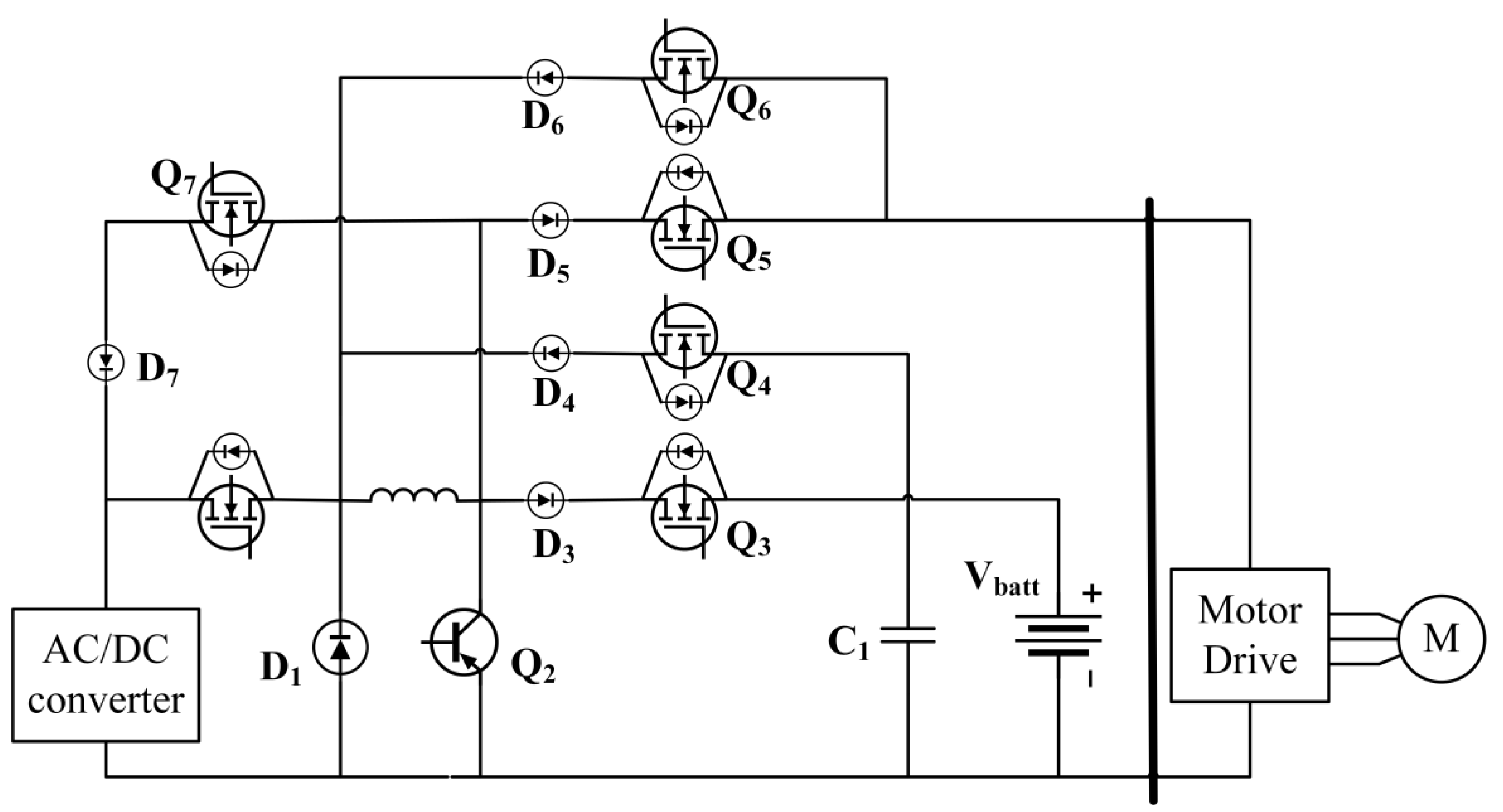
| Direction | Mode | T1 | T2 | T3 | T4 | T5 |
|---|---|---|---|---|---|---|
| Vdc to Vbatt | Boost | On | Off | Off | On | PWM |
| Vdc to Vbatt | Buck | PWM | Off | Off | On | Off |
| Vbatt to Vdc | Boost | Off | On | On | Off | PWM |
| Vbatt to Vdc | Buck | Off | On | PWM | Off | Off |
| Item | PSFB | LLC | SRC |
|---|---|---|---|
| Number of switch blocks | 4 | 4 | 4 |
| Number of diode blocks | 4 | 4 | 4 |
| Number of transformers | 1 | 1 | 2 |
| Number of inductors | 1 | 0 | 0 |
| Additional capacitor | Blocking capacitor | - | - |
| Output filter size | Small | - | Large |
| Configuration | Reference | Operation | Key Features | Application in EV |
|---|---|---|---|---|
| Buck converter | Bose [92] | Step down | Can operate in continuous or discontinuous mode | Sending power to the battery |
| Buck-Boost converter | Bose [92] | Step up and step down | Two quadrant operation of chopper | Regenerative action |
| Interleaved Boost PFC converter | Williamson et al. [46] | Step up with power factor correction | Relatively small input EMI filter | Charging |
| Bridgeless/Dual Boost PFC Converter | Williamson et al. [46] | Step up with power factor correction | Does not require rectifier input bridge | Charging |
| ZVS FB Converter with Capacitive Output Filter | Williamson et al. [46] | AC-DC conversion | Zero voltage switching | Charging |
| Technology | Characteristics |
|---|---|
| Inductive WPT |
|
| Capacitive WPT |
|
| Low frequency permanent magnet coupling power transfer (PMPT) |
|
| Resonant inductive power transfer (RIPT) |
|
| Online power transfer (OLPT) |
|
| Resonant antennae power transfer (RAPT) |
|
| V2G System | Description | Services | Advantages | Limitations |
|---|---|---|---|---|
| Unidirectional | Controls EV charging rate with a unidirectional power flow directed from grid to EV based on incentive systems and energy scheduling |
|
|
|
| Bidirectional | Bidirectional power flow between grid and EV to attain a range of benefits |
|
|
|
| Interaction with RES | Field of Application | Contribution |
|---|---|---|
| Solar PV | Smart home |
|
| Parking lot |
| |
| Grid distribution network |
| |
| Micro grid |
| |
| Wind turbine | Grid distribution network |
|
| Micro grid |
| |
| Solar PV and wind turbine | Smart home |
|
| Parking lot |
| |
| Grid distribution network |
| |
| Micro grid |
|
| Factor | Hurdles |
|---|---|
| Recharging | Weight of charger, durability, cost, recycling, size, charging time |
| Hybrid EV | Battery, durability, weight, cost |
| Hydrogen fuel cell | Cost, hydrogen production, infrastructure, storage, durability, reliability |
| Auxiliary power unit | Size, cost, weight, durability, safety, reliability, cooling, efficiency |
| Limitation | Probable Solution |
|---|---|
| Limited range | Better energy source and energy management technology |
| Long charging period | Better charging technology |
| Safety problems | Advanced manufacturing scheme and build quality |
| Insufficient charging stations | Placement of sufficient stations capable of providing services to all kinds of vehicles |
| High price | Mass production, advanced technology, government incentives |
| Storage System | Energy Converter | Recovered Energy | Application |
|---|---|---|---|
| Electric storage | Electric motor/generator | ~50% | BEV, HEV |
| Compressed gas storage | Hydraulic motor | >70% | Heavy-duty vehicles |
| Flywheel | Rotational kinetic energy | >70% | Formula One (F1) racing |
| Gravitational energy storage | Spring storage system | - | Train |
| References | Algorithm Based on | Application |
|---|---|---|
| Magallan et al. [176] | LuGre dynamic friction model | Driving control system in rear-wheel-drive EV |
| Kang et al. [177] | Optimization-based control allocation strategy | Driving control system in four-wheel-drive EV |
| Tahami et al. [25] | Fuzzy logic | Driving control system in all-wheel-drive EV |
| Wang et al. [178] | Proportional-integral (PI) closed loop control system | Driving control system in in-wheel-drive EV |
| Nam et al. [179] | Extended Kalman filtering (EKF) method | Driving control system in in-wheel-drive EV |
| Zhou et al. [180] | Particle filter and multi-model data fusion | SOC measurement for lithium polymer batteries |
| Moura et al. [175] | Markov process | Power splitting in mid-sized sedan PHEV |
| Hui et al. [181] | Torque control strategy | Heavy hybrid vehicles using a single energy source |
| Chen et al. [182] | Quadratic programming | Reduction of fuel consumption by effective battery current control |
| Li et al. [183] | Fuzzy logic | Attaining maximum fuel efficiency without excess discharging of battery |
| Yuan et al. [184] | Dynamic Programming and Pontryagin’s Minimum Principle | Efficient energy management in parallel HEV using Automatic Manual Transmission or AMT |
| Bernard et al. [185] | Non-causal optimization algorithm | Reduction of hydrogen consumption in FCEV |
| Geng et al. [174] | Equivalent consumption minimization strategy (ECMS) | Energy management in PHEV employing microturbine |
| Su et al. [186] | Estimation of distribution (EDA) algorithm | Intelligent charging of large fleet of PHEVs docked at a municipal charging station |
| Deilami et al. [140] | Maximum sensitivities selection (MSS) optimization | Load management system for intelligent charging |
| Mohamed et al. [187] | Fuzzy controller | V2G system for EV charging parks incorporating renewable generation |
| Geng et al. [120] | Pontryagin’s minimum principle, fuzzy logic | Load shifting while charging EVs in the distribution network |
| Richardson et al. [116] | Linear programming | Enabling high EV penetration in existing residential power system network |
| Sortomme et al [146] | Preferred operating point (POP) algorithm | Maximizing profit from EV charging through an aggregator |
© 2017 by the authors. Licensee MDPI, Basel, Switzerland. This article is an open access article distributed under the terms and conditions of the Creative Commons Attribution (CC BY) license (http://creativecommons.org/licenses/by/4.0/).
Share and Cite
Un-Noor, F.; Padmanaban, S.; Mihet-Popa, L.; Mollah, M.N.; Hossain, E. A Comprehensive Study of Key Electric Vehicle (EV) Components, Technologies, Challenges, Impacts, and Future Direction of Development. Energies 2017, 10, 1217. https://doi.org/10.3390/en10081217
Un-Noor F, Padmanaban S, Mihet-Popa L, Mollah MN, Hossain E. A Comprehensive Study of Key Electric Vehicle (EV) Components, Technologies, Challenges, Impacts, and Future Direction of Development. Energies. 2017; 10(8):1217. https://doi.org/10.3390/en10081217
Chicago/Turabian StyleUn-Noor, Fuad, Sanjeevikumar Padmanaban, Lucian Mihet-Popa, Mohammad Nurunnabi Mollah, and Eklas Hossain. 2017. "A Comprehensive Study of Key Electric Vehicle (EV) Components, Technologies, Challenges, Impacts, and Future Direction of Development" Energies 10, no. 8: 1217. https://doi.org/10.3390/en10081217
APA StyleUn-Noor, F., Padmanaban, S., Mihet-Popa, L., Mollah, M. N., & Hossain, E. (2017). A Comprehensive Study of Key Electric Vehicle (EV) Components, Technologies, Challenges, Impacts, and Future Direction of Development. Energies, 10(8), 1217. https://doi.org/10.3390/en10081217