Engineering Support for Handling Controller Conflicts in Energy Storage Systems Applications


Abstract
:1. Introduction
2. Related Work and Background
2.1. Conflicts Within Storage Systems Use Cases
2.2. Storage Systems Application Development
2.3. Rapid Prototyping of ESS Applications
3. Ontologies for Multi-Use ESS Conflicts Identification
3.1. Categorization of Controller Conflicts
3.2. Ontologies for Modeling ESS Applications
3.3. Formal Representation of the EMS-Ontology
3.4. Methodology for Identifying Controller Conflicts
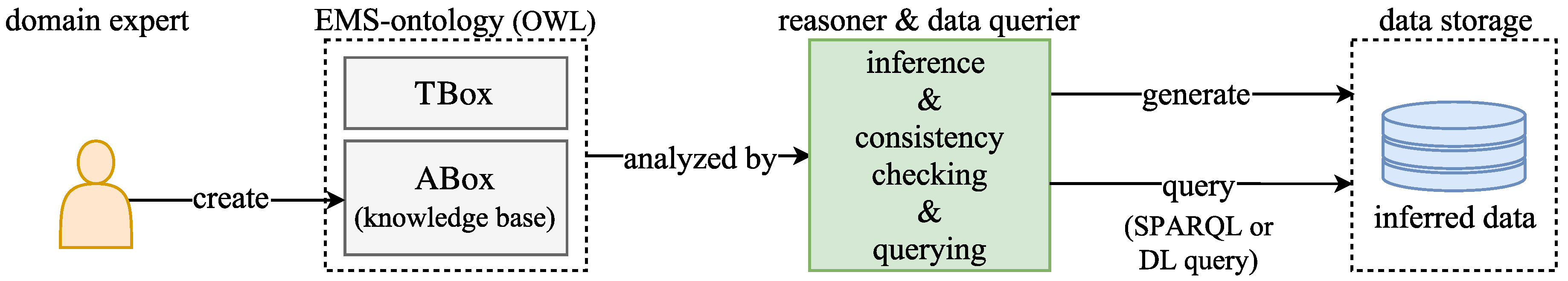
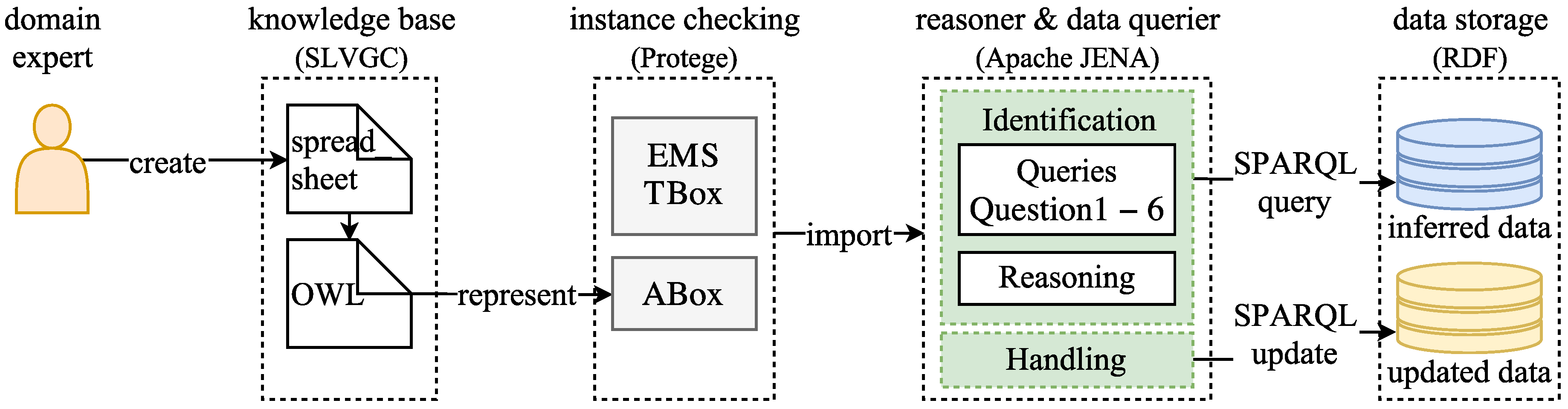
3.5. OWL and SPARQL to Evaluate the EMS-Ontology
4. Handling of Conflicts within ESS Applications
4.1. Handling of Solutions per Conflict Type
4.1.1. Set-Points Down-Regulation
4.1.2. Converter PQ Range Limiter
4.1.3. SOC Estimation and Capacity Allocation
4.1.4. Use Case Specific Solutions
4.2. Extended EMS-Ontology for Handling Conflicts
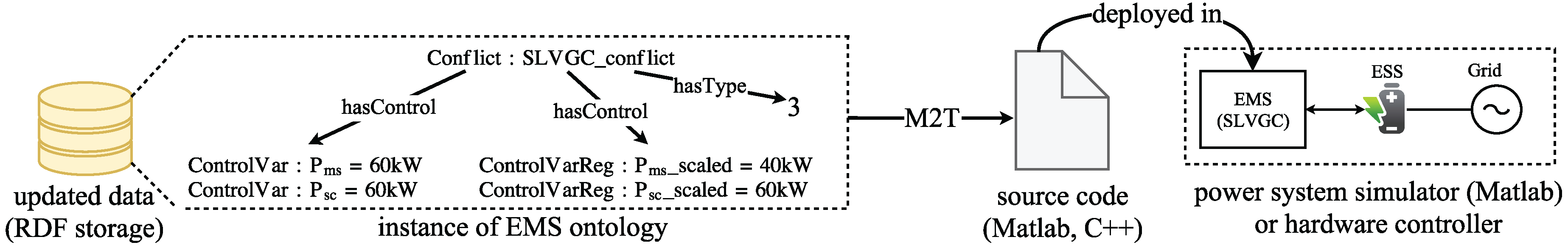
4.3. EMS-Ontology Exploited by the MDE Approach
5. Proof of Concept
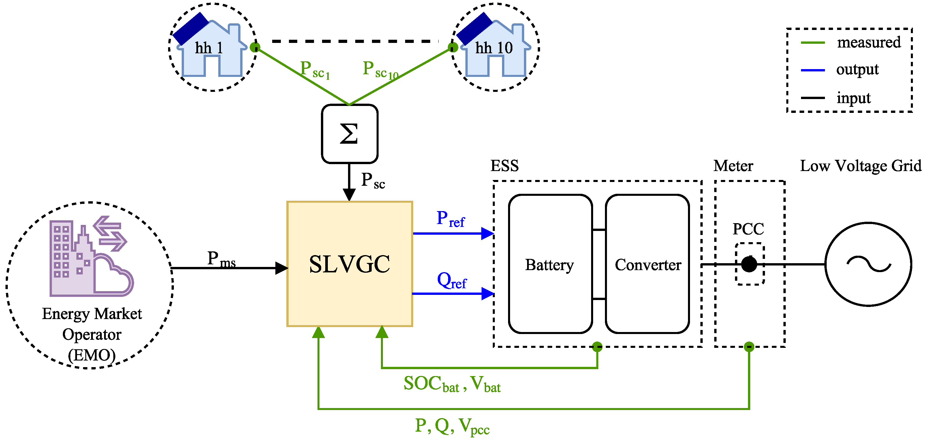
5.1. ESS Services and Setup
5.2. Applying the Ontology-Based Methodology
5.3. Exploiting Inferred Data
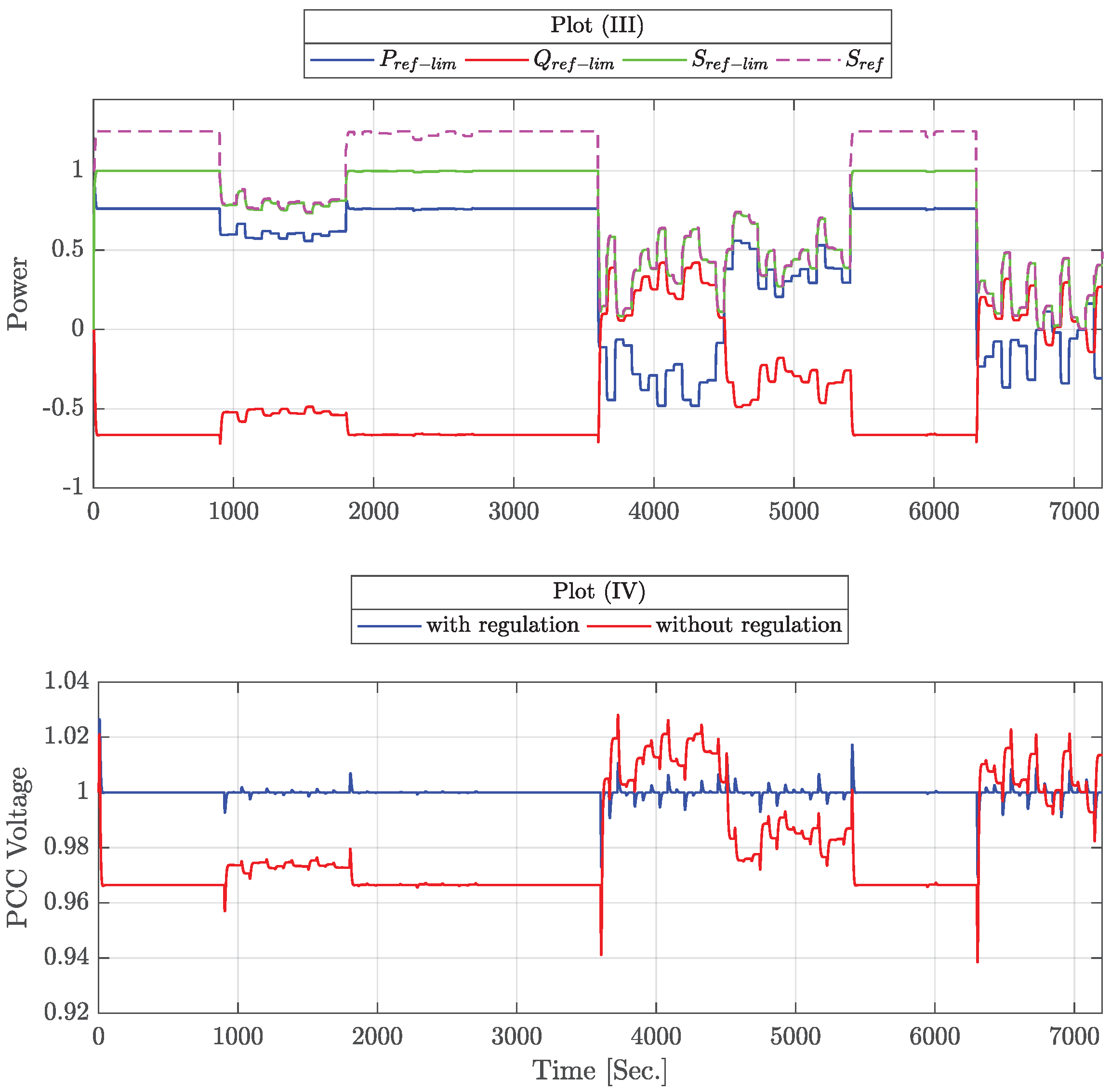
5.4. Simulation Result
6. Conclusions and Future Work
Acknowledgments
Author Contributions
Conflicts of Interest
Abbreviations
| Acronyms | |
| CHIL | Control-Hardware-in-the-Loop |
| DER | Distributed Energy Resources |
| DL | Description Logic |
| DSO | Distribution System Operator |
| EERA | European Energy Research Alliance |
| EMO | Energy Market Operator |
| EMS | Energy Management System |
| ESS | Energy Storage System |
| HLUC | High Level Use Case |
| IEC | International Electrotechnical Commission |
| IRP | International Reporting Project |
| M2M | Model-to-Model |
| M2T | Model-to-Text |
| MDD | Model-Driven Design |
| MDE | Model Driven Engineering |
| OWL | Web Ontology Language |
| PCC | Point of Common Coupling |
| PUC | Primary Use Case |
| PV | Photovoltaic |
| RDF | Resource Description Framework |
| SCADA | Supervisory Control and Data Acquisition |
| SGAM | Smart Grid Architecture Model |
| SLVGC | Smart Low Voltage Controller |
| SOC | State-of-charge |
| TSO | Transmission System Operator |
| UC | Use Case |
| Nomenclature | |
| Active power set by the service i | |
| Reactive power set by the service i | |
| Apparent power set-point of a battery inverter | |
| Active power set-point of a battery inverter | |
| Reactive power set-point of a battery inverter | |
| Maximum reactive power limitation of a battery inverter | |
| Maximum active power limitation of a battery inverter | |
| Maximum apparent power limitation of a battery inverter | |
| Down-regulated value of P adopted by the service i | |
| Down-regulated value of Q adopted by the service i | |
| V | Voltage of the grid |
| P | Active power injected/consumed at the PCC node |
| Q | Reactive power injected/consumed at the PCC node |
| Voltage at the point of common coupling | |
| R | Grid resistance |
| L | Grid inductance |
| Active power set by the self-consumption service | |
| Reactive power set by the grid support controller | |
| Active power set by the market service | |
| Down-regulated value of according to Set-point Down-Regulation strategy | |
| Down-regulated value of according to Set-point Down-Regulation strategy | |
| Down-regulated value of according to Converter PQ Range Limiter strategy | |
| Down-regulated value of according to Converter PQ Range Limiter strategy | |
| Down-regulated value of according to Converter PQ Range Limiter strategy | |
| Down-regulated value of according to Converter PQ Range Limiter strategy | |
| Down-regulated value of according to Converter PQ Range Limiter strategy | |
| State-of-charge of the self-consumption service | |
| State-of-charge of the market service |
Appendix A. TBox of the EMS-Ontology
Appendix B. ABox of the SLVGC Application
Appendix C. Querying the Ontology of the SLVGC Controller

| Multi-Objective Optimization (Conflict ) | |
|---|---|
| DL Query | Query Result |
| (1) Query to know if there is an optimization variable that is optimized by at least two different use case: OptimizationVar and (InvOptimize min 2 (PUC)) | |
| Maximal Limit Dependency of Control Variables (Conflict ) | |
|---|---|
| DL Query | Query Result |
| (1) Search limits of states that depends on other states: Limit and relatedTo min 1 State | |
| (2) Search state that owns the limit : State and hasLimit value Qlimit | |
| (3) Search control variables that control the state Q: ControlVar and Control value Q | |
| (4) Investigate the PUC that controls the state Q: PUC and Control value Q | |
| (5) Search state that is related to the limit : State and relatedTo value | |
| (6) Search control variables that control the state P: ControlVar and Control value P | |
| (7) Search PUC that controls the state P: PUC and Control value P | |
| Set-Point out of Limits (Conflict ) and Set-Point Sign Conflicts (Conflict ) | |
|---|---|
| SPARQL Query | Query Result |
| (1) Search a set-point that is set by at least two control variables: SELECT DISTINCT ?setpoint ?ControlVar WHERE {?setpoint onto:InvSendSetPoint ?ControlVar.} | |
| (2) Investigate the control variables that sets : SELECT DISTINCT ?controlvar WHERE {?controlvar onto:SendSetPoint ?value.} FILTER (?value=)} | |
| (3) Get the value of control variables that set the set-point : SELECT DISTINCT ?controlvar ?controlvalue WHERE { ?controlvar onto:SendSetPoint ?setpoint ?controlvar onto:hasValue ?controlvalue. FILTER (?setpoint=st:)} | } |
| (4) Get the sum of values of control variables and : SELECT (SUM(?controlvalue) as ?TotalSetpoint) WHERE {?controlvar onto:SendSetPoint ?setpoint.?controlvar onto:hasValue ?controlvalue. FILTER (?setpoint=st:)} GROUP BY ?setpoint | |
| (5) Find the limitations of the set-point : SELECT ?Max WHERE {?setpoint onto:hasLimit ?limit.?limit onto:hasMax ?Max. FILTER (?setpoint=st:)} | |
| Set-Point Set by at Least Two Use Cases (Conflict ) | |
|---|---|
| DL Query | Query Result |
| (1) Search set-point that is set by at least two control variables: SetPoint and InvSendSetPoint min 2 ControlVar | |
| (2) Identify the control variables that set the SetPoint : ControlVar and SendSetPoint value | |
| (3) Search the PUC that controls and : PUC and Control value Pms, PUC and Control value Psc | , |
| Interrelated Manipulated Variables (Conflict ) | |
|---|---|
| DL Query | Query Result |
| (1) Search if there are some variables to be regulated or optimized: OptimizationVar and InvOptimize min 1 PUC | |
| (2) Search the PUC that manipulates : PUC and Optimize value | |
| (3) Search the state that is related to : State and relatedTo value | |
| (4) Search the use cases that controls P: PUC and Control value P | , |
Appendix D. Parameters of the SLVGC Use Case
| Parameter | Value/Setting | Description |
|---|---|---|
| R | 0.07 Ohm | resistance of the low voltage line |
| L | 0.255 mH | inductance of the low voltage line |
| V | 230 V rms | low voltage grid |
| f | 50 Hz | nominal frequency of the grid |
| 100 kW | maximum active power of the ESS converter | |
| 100 kVAr | maximum reactive power of the ESS converter | |
| 100 VA | maximum apparent power of the ESS converter | |
| 660 V | nominal voltage of the battery | |
| 600 Ah | capacity of the battery | |
| 50% | initial SoC of the battery | |
| 50% | capacity allocated to the self-consumption use case | |
| 50% | capacity allocated to the market service use case |
References
- Liserre, M.; Sauter, T.; Hung, J. Future Energy Systems: Integrating Renewable Energy Sources into the Smart Power Grid Through Industrial Electronics. IEEE Ind. Electron. Mag. 2010, 4, 18–37. [Google Scholar] [CrossRef]
- Li, X.; Hui, D.; Lai, X. Battery Energy Storage Station (BESS)-Based Smoothing Control of Photovoltaic (PV) and Wind Power Generation Fluctuations. IEEE Trans. Sustain. Energy 2013, 4, 464–473. [Google Scholar] [CrossRef]
- Hollinger, R.; Diazgranados, L.M.; Braam, F.; Erge, T.; Bopp, G.; Engel, B. Distributed solar battery systems providing primary control reserve. IET Renew. Power Gener. 2016, 10, 63–70. [Google Scholar] [CrossRef]
- IEC. Draft IEC 61850-90-7 TR Communication Networks and Systems for Power Utility Automation; Technical Report; International Electrotechnical Commission (IEC): Geneva, Switzerland, 2011. [Google Scholar]
- Büdenbender, K.; Braun, M.; Stetz, T.; Strauss, P. Multifunctional PV Systems offering additional functionalities and improving grid integration. Int. J. Distrib. Energy Resour. Smart Grids 2011, 7, 109–128. [Google Scholar]
- Hänninen, S.; Kyritsis, A.; Abdulhadi, I.; Schwalbe, R.; Strasser, T.; Kosmecki, M.; Sobczak, B.; Rink, R.; Kedra, B.; Wilk, M.; et al. WP 6 Controllable Flexibility Detailed Requirements and Constraints for the Control of Flexibility. Technical Report; ELECTRA Internal Report R6.1; ELECTRA IRP. 2015. Available online: http://orbit.dtu.dk/files/125919193/20150116_R6.1_DetailedRequirementsandConstraintsfortheControlofFlexibility_V1.02.pdf (accessed on 28 August 2017).
- EERA. D4.3 Integration of Storage Resources to Smart Grids: Possible Services, D4.4 Control Algorithms for Storage Applications in Smart Grid; EERA Joint Programme on Smart Grids Sub-Programme 4 Electrical Energy Technologies; Technical Report; EERA: Brussels, Belgium, 2014. [Google Scholar]
- Von Appen, J.; Stetz, T.; Braun, M.; Schmiegel, A. Local Voltage Control Strategies for PV Storage Systems in Distribution Grids. IEEE Trans. Smart Grid 2014, 5, 1002–1009. [Google Scholar] [CrossRef]
- CEN-CENELEC-ETSI Smart Grid Coordination Group. Reference Architecture for the Smart Grid; Technical Report; CEN-CENELEC-ETSI: Brussels, Belgium, 2012. [Google Scholar]
- IEC. IEC 62559: Use Case Methodology; Technical Report; International Electrotechnical Commission (IEC): Geneva, Switzerland, 2015. [Google Scholar]
- Zanabria, C.; Pröstl Andrén, F.; Kathan, J.; Strasser, T. An approach for the handling of controller conflicts within multi-functional energy storage systems. In Proceedings of the 24th International Conference on Electricity Distribution (CIRED), Glasgow, UK, 12–15 June 2017. [Google Scholar]
- Bletterie, B.; Tayyebi, A.; Kadam, S.; Le Baut, J.; Stöckl, J.; Kathan, J.; Einfalt, A. A novel concept for combining distribution network and system support services for storage systems. In Proceedings of the 2017 IEEE Manchester PowerTech, Manchester, UK, 18–22 June 2017; pp. 1–6. [Google Scholar]
- Perera, B.; Ciufo, P.; Perera, S. Advanced point of common coupling voltage controllers for grid-connected solar photovoltaic (PV) systems. Renew. Energy 2016, 86, 1037–1044. [Google Scholar] [CrossRef]
- Consentec GmbH. Description of Load-Frequency Control Concept and Market for Control Reserves; Study Commissioned by the German TSOs; Consentec GmbH: Aachen, Germany, 2014. [Google Scholar]
- Braam, F.; Hollinger, R.; Engesser, M.L.; Müller, S.; Kohrs, R.; Wittwer, C. Peak shaving with photovoltaic-battery systems. In Proceedings of the Innovative Smart Grid Technologies Conference Europe (ISGT-Europe), Istanbul, Turkey, 12–15 October 2014; pp. 1–5. [Google Scholar]
- Riffonneau, Y.; Bacha, S.; Barruel, F.; Ploix, S. Optimal Power Flow Management for Grid Connected PV Systems With Batteries. IEEE Trans. Sustain. Energy 2011, 2, 309–320. [Google Scholar] [CrossRef]
- Andrén, F.; Lehfuss, F.; Strasser, T. A development and validation environment for real-time controller-hardware-in-the-loop experiments in Smart Grids. Int. J. Distrib. Energy Resour. Smart Grids 2013, 9, 27–50. [Google Scholar]
- Zanabria, C.; Andrén, F.P.; Kathan, J.; Strasser, T. Towards an integrated development of control applications for multi-functional energy storages. In Proceedings of the IEEE 21st International Conference on Emerging Technologies and Factory Automation (ETFA), Berlin, Germany, 6–9 September 2016; pp. 1–4. [Google Scholar]
- Faschang, M.; Schwalbe, R.; Einfalt, A.; Mosshammer, R. Controller hardware in the loop approaches supporting rapid prototyping of smart low voltage grid control. In Proceedings of the 2014 IEEE PES Innovative Smart Grid Technologies Conference Europe (ISGT-Europe), Istanbul, Turkey, 12–15 October 2014; pp. 1–5. [Google Scholar]
- Hitzler, P.; Krötzsch, M.; Rudolph, S. Foundations of Semantic Web Technologies; Chapman & Hall/CRC: London, UK, 2009. [Google Scholar]
- Schachinger, D.; Kastner, W.; Gaida, S. Ontology-based abstraction layer for smart grid interaction in building energy management systems. In Proceedings of the IEEE International Energy Conference (ENERGYCON), Leuven, Belgium, 4–8 April 2016; pp. 1–6. [Google Scholar]
- Samirmi, F.D.; Tang, W.; Wu, Q. Fuzzy Ontology Reasoning for Power Transformer Fault Diagnosis. Adv. Electr. Comput. Eng. 2015, 15, 107–114. [Google Scholar] [CrossRef]
- Baader, F. The Description Logic Handbook: Theory, Implementation and Applications; Cambridge University Press: Cambridge, UK, 2003. [Google Scholar]
- Brambilla, M.; Cabot, J.; Wimmer, M. Model-Driven Software Engineering in Practice. Synth. Lect. Softw. Eng. 2012, 1, 1–182. [Google Scholar] [CrossRef]
- Siegel, J. Developing in OMG’s New Model-Driven Architecture; Object Management Group (OMG): Needham, MA, USA, 2001. [Google Scholar]
- Dänekas, C.; Neureiter, C.; Rohjans, S.; Uslar, M.; Engel, D. Towards a model-driven-architecture process for smart grid projects. In Digital Enterprise Design & Management; Springer: Warsaw, Poland, 2014; pp. 47–58. [Google Scholar]
- Andrén, F.; Strasser, T.; Kastner, W. Engineering Smart Grids: Applying Model-Driven Development from Use Case Design to Deployment. Energies 2017, 10, 374. [Google Scholar] [CrossRef]
- Working Group Sustainable Processes (SG-CG/SP). CEN-CENELEC-ETSI Smart Grid Coordination Group—Sustainable Processes; Technical Report; CEN-CENELEC-ETSI: Brussels, Belgium, 2012. [Google Scholar]
- Kalibatiene, D.; Vasilecas, O. Survey on Ontology Languages. In Perspectives in Business Informatics Research; Grabis, J., Kirikova, M., Eds.; Springer: Berlin/Heidelberg, Germany, 2011; Volume 90, pp. 124–141. [Google Scholar]
- Tayyebi, A.; Bletterie, B.; Kupzog, F. Primary Control Reserve and Self-Sufficiency Provision with Central Battery Energy Storage System. In Proceedings of the NEIS Conference, Hamburg, Germany, 21–22 September 2017. in press. [Google Scholar]
- Hua, Y.; Zander, S.; Bordignon, M.; Hein, B. From AutomationML to ROS: A model-driven approach for software engineering of industrial robotics using ontological reasoning. In Proceedings of the 2016 IEEE 21st International Conference on Emerging Technologies and Factory Automation (ETFA), Berlin, Germany, 6–9 September 2016; pp. 1–8. [Google Scholar]
- Apache Jena. Ontology API, 2012. Available online: https://jena.apache.org/documentation/ontology/ (accessed on 12 March 2017).
- World Wide Web Consortium. SPARQL 1.1 Query Language, 2008. Available online: https://www.w3.org/TR/sparql11-query/ (accessed on 11 February 2017).
- Tayyebi, A. Modelling and Simulation of a Multifunctional PV Electrochemical Storage System. Master’s Thesis, University of Oviedo, Oviedo, Spain, 2016. [Google Scholar]
- Yazdani, A.; Iravani, R. Voltage-Sourced Converters in Power Systems: Modeling, Control, and Applications; John Wiley & Sons: Hoboken, NJ, USA, 2010. [Google Scholar]
- Bredillet, P.; Lambert, E.; Schultz, E. CIM, 61850, COSEM standards used in a model driven integration approach to build the smart grid service oriented architecture. In Proceedings of the First IEEE International Conference on Smart Grid Communications (SmartGridComm), Gaithersburg, MD, USA, 4–6 October 2010; pp. 467–471. [Google Scholar]
- Heussen, K.; Gehrke, O.; Niemann, H. On early conflict identification by requirements modeling of energy system control structures. In Proceedings of the IEEE 20th Conference on Emerging Technologies & Factory Automation (ETFA), Luxembourg City, Luxembourg, 8–11 September 2015; pp. 1–8. [Google Scholar]
- Uslar, M.; Heussen, K. Towards modeling future energy infrastructures—The ELECTRA system engineering approach. In Proceedings of the PES Innovative Smart Grid Technologies Conference Europe (ISGT-Europe), Ljubljana, Slovenia, 9–12 October 2016; pp. 1–6. [Google Scholar]
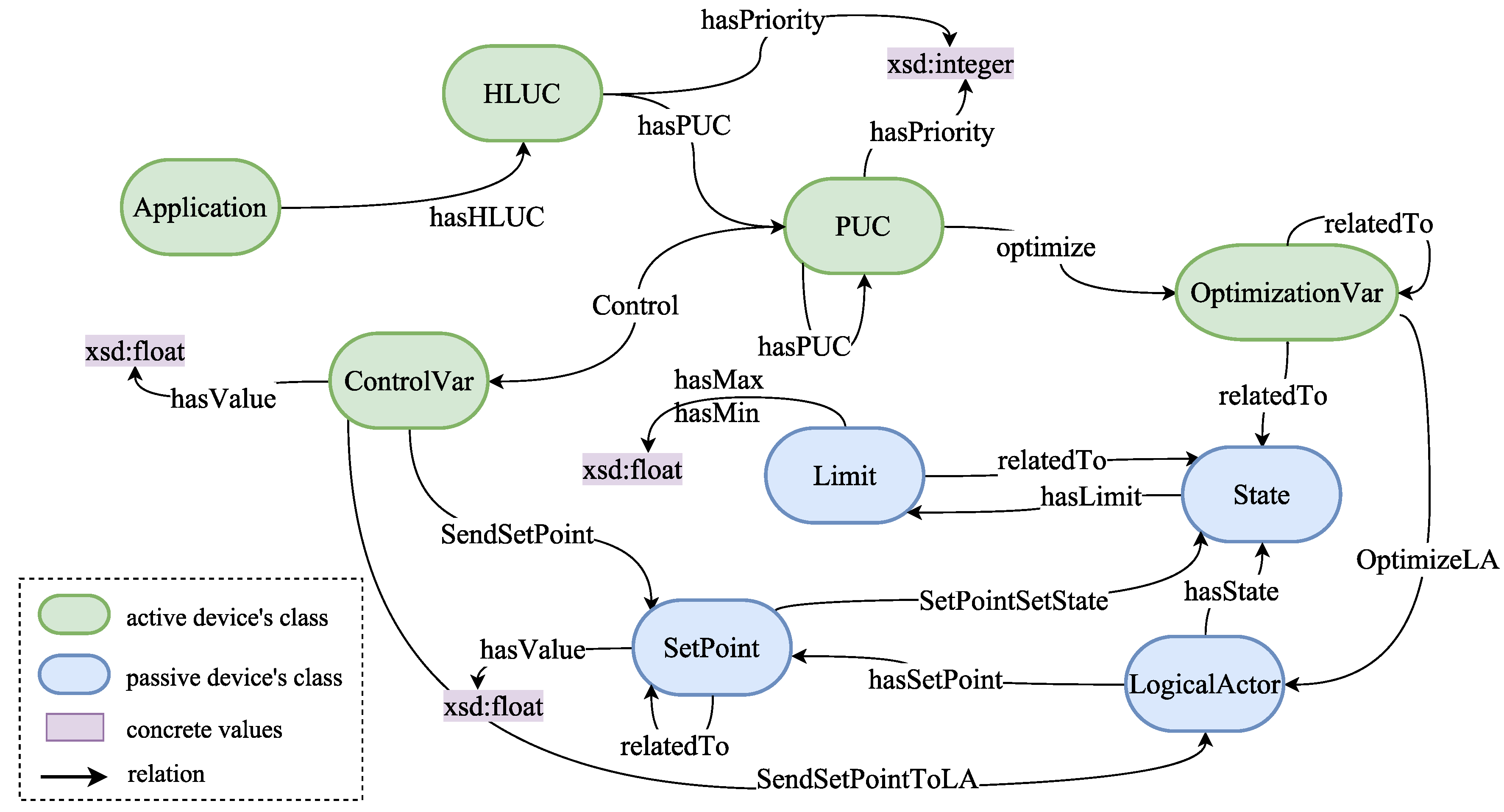
| Concept | Description |
|---|---|
| This concept represents EMS control applications. | |
| High Level Use Cases () involve the main functions covered by an EMS controller (frequency control, voltage control, etc.). | |
| Primary Use Cases () specify functions defined in a (e.g., data acquisition, PI control). | |
| This concept categorizes control variables sent by a (e.g., voltage control sends the control variable P to control injection of active power of an ESS). | |
| Represents optimization functions and manipulated variables of a or (e.g., a minimization of costs, minimizes a cost function defined by , in this case is classified as an ). | |
| Value that is set by a or and belongs to a (e.g., a frequency/voltage control sets the set-point active power (P) of an ESS) | |
| Represents all kind of systems and physical devices controlled by an (e.g., ESS). | |
| Variables or parameters that belong to a (e.g., SOC and active power of an ESS). | |
| Represent technical limitations of a (e.g., ESS converter maximal active power limit). |

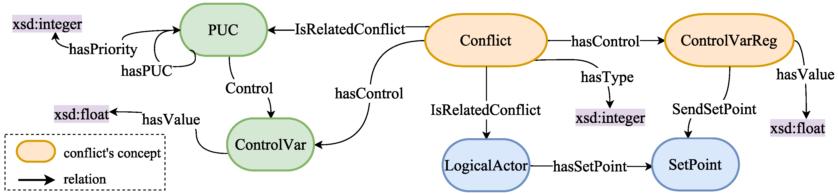
| Concept | Description |
|---|---|
| This concept enables the collecting of relevant information with respect to a categorized conflict. It means use cases in conflict, type of conflict and physical devices or systems categorized as that are involved in a conflict. | |
| The occurrence of needs to scale set-points values down. Thus, the representation of down-regulated values is done by the concept. Moreover, this concept has the total set-point value to be set in a . |

| Use Case/Name | Objective | Stakeholder | Description & Examples |
|---|---|---|---|
| electric energy time shift/ | market integration | market operator | Economical benefits are maximized. ESS is charged when the spot market prices are low and during off-peak times and usually discharged when prices are high. It is based on a daily optimization strategy [7]. |
| voltage control/ | power quality | DSO | The rise of voltage levels can be regulated by injecting reactive power or by consuming active power. ESS participates in voltage regulation by implementing different control strategies [8,13]. |
| primary control reserve/ | power system stability | TSO | A high penetration of DER may result in a change of the grid frequency. The ESS participates in the frequency regulation by injecting/consuming active power [3,14]. Such a service is usually used by the TSO. |
| peak-shaving/ | reduction of supply cost | end user | ESS is used to prevent high peaks of consumption. The ESS is discharged when a load higher than a specific set-point is switch on [15]. |
| minimization of prices/ | reduction of supply cost | end user | Electricity costs are minimized by an objective function. It takes into account the cash received from selling energy and the cash paid for energy consumed. Moreover, forecast on load consumption, DER device generation and electricity prices (€/kWh) are calculated [16]. |
| self-consumption/ | reduction of supply cost | end user | Local self-consumption is the main target. The difference of the local generation and demand is charged into the battery and discharged from it when the demand exceeds the local generation [7]. |
| Conflict Name/Type | Description & Examples |
|---|---|
| Multi-objective optimization/ | Two UCs are optimizing the functions and respectively. This entails a conflict when and need to be manipulated simultaneously. For instance, an EMS supports to the stabilization of the grid frequency () and to the minimization of energy prices (). An over frequency event would require a reduction of the active power (P). In the meantime, requires to increase P, then a coordination of control schemes is needed. |
| Maximal limit dependency of control variables/ | Two UCs are controlling and respectively. Additionally, the limits of depend on the value of (i.e., ). For instance, an EMS contributes to voltage regulation () by setting the reactive power (Q). Besides of this the EMS receives set-points to deliver active power (P) in a context of provision. The limits of P depend on Q according to . Hence, an alignment of services is suitable to avoid the saturation of P and Q . |
| Set-point out of limits/ | This conflict occurs when at least two UCs control the same variable and the total set-point value exceeds the limits. For instance an EMS provides Primary Control Reserve (PCR) and market service () by receiving set-points from EMO and TSO to control P. Even when each set-point respects the limits of P an overall violation of the set-points is possible. |
| Set-point sign conflicts/ | This conflict is based on the tracking of active power provision by monitoring the State of Charge (SOC) of the ESS. On this basis, when more than one service affects the value of P by two set-points with opposite signs, the tracking of single-services is lost. For instance, an EMS provides and , then the value of P is set. When the total set-point is zero, the SOC remains the same leading to a wrongly non-provision of the services conclusion. |
| Set-point set by at least two UCs/ | At least two different use cases have the intention of controlling the same variable of a system. |
| Interrelated manipulated variables/ | A UC is controlling a variable to manipulate whereas a second UC is controlling to manipulate . Additionally one of the following statements is true: or . It means that the manipulated variable or is affected by the first UC and the second one. For instance, an EMS provides voltage control () by injecting/consuming reactive power (Q). In the meantime, the TSO requires to balance the active power (P) in a context. As a consequence, voltage of the grid is regulated by however it is also affected by . An analysis of the whole multi-functional system (voltage control and PCR) is required. |
| Question/Conflict Type | DL/SPARQL Notation |
|---|---|
| Question 1: What are the variables that are optimized or regulated by at least two different services?/ | |
| Question 2: What are the states that are controlled by a use case application and its limits are in turn controlled by a second control application?/ | |
| Question 3: Does a set of variables exist which intends to control a set-point of an ESS, causing a violation of technical limits imposed to this set-point?/ | supported with SPARQL (see Appendix C) |
| Question 4: Are there a set of control variables that control a determined set-point of an ESS and the multiplication of their values is negative?/ | supported with SPARQL (see Appendix C) |
| Question 5: What are the variables that control a same set-point of an ESS?/ | |
| Question 6: What are the variables that are manipulated by a service and are affected by a second use case?/ |
| Conflict/Type | Detected | Conclusion Derived from Queries | Handling Solution |
|---|---|---|---|
| Multi-objective optimization/ | X | There is not any variable that is intended to be optimized or regulated by two different use cases then conflict is not identified. Control strategies regarding self-consumption and market services are run externally, thus the SLVGC application receives set-points from household and EMO. It could be the case that those services are in conflict but as the SLVGC application has no further information regarding those services then is dismissed. | Not required |
| Maximal limit dependency of control variables/ | ✓ | The limit of Q is defined by the state P (). This state P is controlled by the use cases self-consumption and market service through the control variables and . Additionally, the state Q is controlled by voltage control use case through . A conflict involving the control variables and is detected. Then a coordination between the services in conflict is required to avoid a saturation of P and Q. | Converter PQ range limiter |
| Set-point out of limits/ | ✓ | The set-point is set by two control variables: and . The total value to be set exceeds the active power limit , then a conflict is identified | Down-regulation of set-points |
| Set-point sign conflicts/ | X | The values of control variables and have the same sign then a conflict is dismissed. However those values evolve over time, thus the EMS-ontology cannot predict the conflict . Identification of conflict should take place during real-time operation or simulation of the SLVGC application. | SOC estimation and capacity allocation |
| Set-point set by at least two use cases/ | ✓ | The controllers market service and self-consumption have the intention of setting the set-point of the ESS, then conflict is detected. This conflict is not considered harmful by the domain expert. Thus, no handling solutions are executed. | Not required |
| Interrelated manipulated variables/ | ✓ | The use cases market service and self-consumption control the state P. Additionally the value of this state affects the PCC voltage (). Thus, is affected bv market service and self-consumption use cases. On the other hand, is manipulated by voltage control to regulate the PCC voltage, then is identified. | Reactive power voltage controller |
© 2017 by the authors. Licensee MDPI, Basel, Switzerland. This article is an open access article distributed under the terms and conditions of the Creative Commons Attribution (CC BY) license (http://creativecommons.org/licenses/by/4.0/).
Share and Cite
Zanabria, C.; Tayyebi, A.; Pröstl Andrén, F.; Kathan, J.; Strasser, T. Engineering Support for Handling Controller Conflicts in Energy Storage Systems Applications. Energies 2017, 10, 1595. https://doi.org/10.3390/en10101595
Zanabria C, Tayyebi A, Pröstl Andrén F, Kathan J, Strasser T. Engineering Support for Handling Controller Conflicts in Energy Storage Systems Applications. Energies. 2017; 10(10):1595. https://doi.org/10.3390/en10101595
Chicago/Turabian StyleZanabria, Claudia, Ali Tayyebi, Filip Pröstl Andrén, Johannes Kathan, and Thomas Strasser. 2017. "Engineering Support for Handling Controller Conflicts in Energy Storage Systems Applications" Energies 10, no. 10: 1595. https://doi.org/10.3390/en10101595
APA StyleZanabria, C., Tayyebi, A., Pröstl Andrén, F., Kathan, J., & Strasser, T. (2017). Engineering Support for Handling Controller Conflicts in Energy Storage Systems Applications. Energies, 10(10), 1595. https://doi.org/10.3390/en10101595