Article

Thermo-Economic Performance Analysis of a Regenerative Superheating Organic Rankine Cycle for Waste Heat Recovery

Key Lab of Condition Monitoring and Control for Power Plant Equipment, North China Electric Power University, Ministry of Education, Baoding 071003, China
*
Author to whom correspondence should be addressed.
Energies 2017, 10(10), 1593; https://doi.org/10.3390/en10101593
Submission received: 28 July 2017 / Revised: 6 October 2017 / Accepted: 9 October 2017 / Published: 13 October 2017
(This article belongs to the Section I: Energy Fundamentals and Conversion)

Abstract

:
The Organic Rankine Cycle (ORC) is a promising form of technology for recovering low-grade waste heat. In this study, a regenerative ORC system is established to recover the waste flue gas of 160 °C. Focusing on thermodynamic and economic performance while simultaneously considering the limitations of volume flow ratio (VFR) and the effect of superheat, working fluid selection and parameter optimization have been investigated. The optimization of the evaporation temperature is carried out by analyzing the variation of net power output and specific investment cost (SIC). Then, the net power output, specific net power output, total exergy destruction rate, VFR, total capital cost, and levelized electricity cost (LEC) are selected as criteria, and a fuzzy multi-criteria evaluation method is adopted to select a more suitable working fluid and determine the optimal degree of superheat. In addition, the preheating coefficient, latent heat coefficient, superheating coefficient, and internal heat coefficient were proposed to explore the effect of working fluid critical temperature on thermal efficiency. Research studies demonstrate that there is an optimal evaporation temperature, maximizing net power output and minimizing the SIC. Isohexane and butane have greater specific net power output due to greater latent heat. A suitable degree of superheat is not only conducive to improving the working capacity of working fluids, but also reduces the VFR, total capital cost, SIC, and LEC for different working fluids. Thus, the system’s thermodynamic and economic performance—as well as the operational stability—are improved. Among the six working fluids, butane exhibits the best comprehensive performance, and its optimal evaporation temperature and degree of superheat are 100 °C and 5 °C, respectively.

1. Introduction

The Organic Rankine Cycle (ORC) has been widely investigated due to its advantages with respect to the recovery of low-grade heat sources such as waste flue gas heat, solar energy, and geothermal energy. The key superiority of such technology is that organic fluids generally have a lower boiling temperature and higher evaporation pressure compared with water, which can be reached more easily; therefore, it is much easier for the ORC to convert low-grade heat into electricity [1,2,3,4,5,6].
ORC technology is more mature in terms of the utilization of waste heat than other options, including Stirling [7], thermofluidic heat engines [8], and the Up-THERM heat converter [9]. However, there are still inherent limitations to the amount of energy that can be extracted from the waste heat sources due to the low temperature. Challenges, like low thermal efficiency and low maximum power-producing potential, result from low heat source temperature. Thus, in order to address these challenges, extensive research studies have been performed on working fluid selection and optimization of the system. Roy et al. [10,11] conducted a study of a basic ORC and a regenerative ORC using R12, R123, R134a, and R717as working fluids under different heat source temperature conditions. The thermal efficiency and net power output were the optimization indicators, and it was found that of the four working fluids, R123 produced the maximum net power output and thermal efficiency. A novel design method called the “thermodynamic inverse problem” was proposed by Chen et al. [12], which directly relates the turbine power output with thermal efficiency. The new method provides a new strategy for fully coupling the ORC with the low-grade waste heat sources. Gao et al. [13] investigated the performance of both superheated and saturated ORC systems using nine working fluids. The entire heating process of working fluids was divided into three parts (preheating, latent heat, and superheating) to compare the thermal efficiency of different working fluids. Several investigations focusing on the effect of working fluid properties on thermal efficiency have been carried out [14,15,16,17], and it was concluded that the higher critical temperature of working fluids, the greater thermal efficiency of the ORC system. Larjola [18] indicated that higher power output and lower irreversibility were obtained when the heating curve of the working fluids ‘follows’ better the cooling curve of the heat source. Therefore, two methods including replacing subcritical ORC with supercritical ORC [19,20] and replacing pure working fluids with zeotropic mixture working fluids [21,22,23,24] were put forward to enable a closer thermal match between the heat source and working fluids.
In order to improve ORC system thermal efficiency, both regeneration and turbine bleeding was incorporated to modify the basic ORC [25]. For dry working fluids, the expansion process in turbines terminates in the superheat region. Hence, prior to directing the superheated vapor to the condenser, it is beneficial to incorporate an internal heat exchanger (IHE) in the system to regenerate the working fluid exiting the pump. In this method, the average evaporating temperature increases, while the condensation temperature decreases. According to Carnot, a higher thermal efficiency is obtained [15,26,27,28]. Javanshir et al. [2] evaluated the thermal efficiency and net power output of the regenerative ORC using 14 different dry working fluids. The results showed that regeneration can decrease the difference in thermal efficiencies among different working fluids but it does not change the specific net power output. In a small-scale ORC system, simpler system architectures are usually preferred due to the limitations of capital cost and safety factors [29]. Thus, turbine bleeding regeneration is not appropriate for a small-scale ORC system because of its complicated system architecture. In this paper, the regenerative ORC system is adopted for recovery of low grade-waste flue gas.
The brief reviews presented above are mainly focused on thermodynamic performance, however working fluid selection and parametric optimization are not merely determined by thermodynamic performance. Economic factors should be considered simultaneously. Lemmens [30] estimated the price of an ORC based on cost-engineering techniques. The investment of heat exchangers account for a large proportion of the total system capital cost [31]. Zhang et al. [32] compared the thermo-economic performance of an ORC system based on different heat exchanger configurations. Heberle [24,33], Feng et al. [22], and Oyewunmi and Markides [34] carried out thermo-economic comparison between zeotropic mixtures and pure working fluids. The results showed that the mixtures present better thermodynamic performance but worse economic performance than the pure working fluids. Wang et al. [35] took exergy efficiency and overall capital cost as optimization objectives simultaneously, and the non-dominated sorting genetic algorithm II (NSGA-II) was used to solve the multi-objective optimization problems. The net present value (NPV) and payback period (PBP) as technology–economy indicators were applied to evaluate the economic performance of an Organic Rankine Cycle in cement production [36]. Integration of the ORC system with other thermal systems attracted the attention of some researchers, and thermo-economic analyses of these integration systems were carried out [37,38].
Many efforts have been made with respect to working fluid selection and parametric optimization, considering thermodynamic or economic factors. However, very few similar works focus on discussing the limitation of volume flow ratio (VFR) [28,39,40], a factor which has a significant influence on turbine design and manufacture. In this study, a turbine is selected as expander in the investigated regenerative ORC system. The limitations of VFR need to be considered in the working fluid selection and in parametric optimization. The optimization of the evaporation temperature and the degree of superheat is carried out by analyzing the variation of thermodynamic and economic criteria. A suitable working fluid is determined simultaneously. Moreover, the preheating coefficient, latent heat coefficient, superheating coefficient, and internal heat coefficient were put forward to reveal the link between the working fluid critical temperature and the thermal efficiency.

2. Mathematic and Physical Models

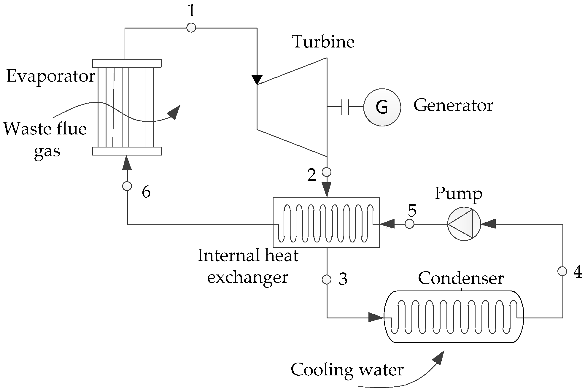
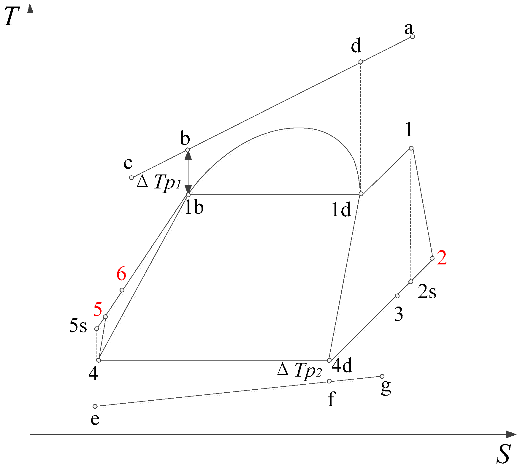
2.1. Structure and Working Principles of the System

The basic layout of the components of a regenerative ORC system for waste heat recovery is depicted in Figure 1. The system consists of an evaporator driven by the waste flue gas, a turbine, an internal heat exchanger (IHE), a condenser, and a working fluid pump. The thermodynamic process for such a regenerative ORC system is illustrated in a typical T–s diagram, as shown in Figure 2. Firstly, the organic working fluid from a condenser is compressed by the pump to become a high-pressure liquid, and then it is heated in an internal heat exchanger by utilizing the sensible heat of turbine exhaust. Secondly, the working fluid is fed to the evaporator, where it is vaporized and converts to superheated vapor. In the above-mentioned processes, the organic working fluid consecutively passes through a subcooled liquid state, a saturated liquid state, a saturated vapor state, and a superheated vapor state. The high-pressure superheated vapor enters a turbine and its enthalpy is converted into mechanical work with a decrement in pressure and temperature. Ideally, this is an isentropic expansion process of 1–2 s. However, because the turbine efficiency never reaches 100%, the real state at the exit of turbine is demonstrated by point 2. Afterwards, turbine exhaust flows through the internal heat exchanger and condenser to be liquefied and condensed into a saturated liquid.

2.2. Thermodynamic Model

To simplify the thermodynamic analysis of the regenerative ORC, a set of general assumptions is introduced in this study:
(1)
The regenerative ORC system is under steady state.
(2)
Heat losses to or from the environment as well as the kinetic and potential energy changes are neglected.
(3)
A saturated liquid state is supposed at the condenser outlet.
(4)
Pressure drops in the evaporator, condenser, internal heat exchanger, and related pipelines are ignored.
Based on the above assumptions as well as mass and energy balances, the mathematical model of each component of the regenerative system was established. According to the models, the ORC simulation is performed with a combination of MATLAB (R2013a, MathWorks, Natick, MA, USA) and REFPROP 8.0 (NIST, Gaithersburg, MD, USA) software. The net power output, thermal efficiency, heat recovery efficiency, VFR, specific net power output, total exergy destruction rate, total capital cost, SIC, and LEC are calculated as the system performance indicators.
Evaporator (6-1): Working fluid absorbs heat from the waste flue gas, which is an isobaric process. The heat transfer rate from the heat source is:
Q eva = m f ( h 1 h 6 ) = m gas c p ( T a T b )
The exergy destruction rate in the evaporator can be written as:
I eva = T amb m f [ ( s 1 s 6 ) ( h 1 h 6 ) / T H ]
where TH is the temperature of the heat source, taking the arithmetic mean temperature of the flue gas inlet and outlet temperature.
T H = ( T a + T c ) / 2
Turbine (1-2): The superheated vapor expands in the turbine to generate power. The isentropic efficiency of the turbine is given by:
η s , T = ( h 1 h 2 ) / ( h 1 h 2 s )
The power generated the turbine is expressed as:
W T = m f ( h 1 h 2 ) = m f ( h 1 h 2 s ) η s , T
The exergy destruction rate in the turbine can be expressed as:
I T = m f T amb ( s 2 s 1 )
Internal heat exchanger (2-3/5-6): In this process, the high pressure working fluid exiting from the pump is heated by the turbine exhaust. The energy balance for the internal heat exchanger can be expressed as:
Q IHE = m f ( h 2 h 3 ) = m f ( h 5 h 6 )
The effectiveness of internal heat exchanger can be written as:
ε = ( T 2 T 3 ) / ( T 2 T 5 )
The exergy destruction rate in the internal heat exchanger is evaluated as:
I IHE = m f T amb [ ( s 6 s 5 ) + ( s 3 s 2 ) ]
Condenser (3-4): The low pressure vapor flows out the internal heat exchanger and is led to the condenser where it is condensed to the saturated liquid. The condensation heat is expressed as
Q con m f ( h 3 h 4 )
The exergy destruction rate in the condenser can be given as:
I con = m f T amb [ ( s 4 s 3 ) + ( h 3 h 4 ) / T L ]
where TL is the temperature of the cold source, taking the arithmetic mean temperature of the cooling water inlet and outlet temperature.
T L = ( T g + T e ) / 2
Pump (4-5): In an ideal case, it is an isentropic pumping process (4–5 s). Because the pumping isentropic efficiency never reaches 100%, the practical process is an entropy-increasing one. The isentropic efficiency of the pump is defined as:
η s , p = ( h 5 s h 4 ) / ( h 5 h 4 )
The power consumed by the pump is expressed as:
W p = m f ( h 5 h 4 ) = m f ( h 5 s h 4 ) / η s , p
The exergy destruction rate in the pump is given by:
I p = m f T amb ( s 5 s 4 )
The total exergy destruction rate of the cycle is calculated by:
I Toatl = I eva + I T + I IHE + I con + I p = m f T amb [ ( h 1 h 6 ) / T H + ( h 3 h 4 ) / T L ]
The net power produced by the ORC is expressed as:
W net = W T W p
In order to evaluate the working capacities of various working fluids objectively, the specific net power output as a new index is introduced.
P net = W net / m f
The ORC thermal efficiency is the ratio of the net power output to the input heat.
η the = W net / Q eva
The power consumed by the pump is relatively small compared with the turbine power output and input heat, thus it can be neglected to simplify the theoretic analysis of thermal efficiency. The ORC thermal efficiency can be expressed as Equation (20) according to the first law of thermodynamic.
η the ( Q eva Q con ) / Q eva = 1 Q con / Q eva
Q eva = Q l + γ H + Q sup Q IHE
where Ql is the heat received by the liquid working fluid, γ H is the latent heat at evaporating temperature, and Qsup is the heat transfer to the superheated vapor.
Q l = m f ( h 1 b h 5 )
γ H = m f ( h 1 d h 1 b )
Q sup = m f ( h 1 h 1 d )
Therefore, the thermal efficiency of the cycle can be written as:
η the 1 Q con / ( Q l + γ H + Q sup Q IHE )
There is a low degree of superheat at the condenser inlet because of the incorporation of an internal heat exchanger. Therefore, the most part of the heat transferred to the cold source is the latent heat at condensing temperature. For a given condensing temperature, the latent heat is constant for each working fluid. Through thermodynamic derivation Equation (25) is further expressed as:
η the 1 1 / ( δ l + δ H + δ sup δ IHE )
The power consumed by the pump is neglected in the thermal efficiency theoretical analysis process, and this simplification does not lose generality. Therefore, Equation (26) can be used to analyze the variation of the thermal efficiency.
The heat recovery efficiency is defined as the heat received from the waste heat divided by the maximum usable energy released by the waste heat source.
ϕ = Q eva / Q max = ( T a T c ) / ( T a T 5 )
Substituting Equation (10)–(18) yields:
W net = Q eva η the = Q max ϕ η the
The volume flow ratio (VFR) is very important for turbine design, which has a significant influence on turbine efficiency and geometry [40]. This factor accounts for the effects of volume expansion and compressibility [28,39]. Then, the parameter was investigated in other works to study the characters of the turbine in the ORC system [28,39,40]. The VFR is defined as the specific volume variation of working fluid across the turbine [28], and a moderate VFR is preferred in the ORC system.
VFR = v out / v in

2.3. Economical Model

In the ORC system, the overall capital cost is assigned to each individual component. Shell-tube heat exchangers are employed in the regenerative ORC system. Due to the various heat transfer coefficients caused by different working fluid phase state, the evaporator is divided into two single-phase flow regions and one two-phase flow region, and the condenser is divided into one single-phase flow region and one two-phase flow region [41]. The heat transfer area can be calculated by
A i = Q i / ( U i × Δ T m )
where ΔTm is the logarithmic mean temperature difference which is expressed as:
Δ T m = Δ T max Δ T min ln ( Δ T max / Δ T min )
where ΔTmax and ΔTmin are the maximum and minimum temperature difference at the inlet or outlet of heat exchangers, respectively.
The mean overall heat transfer coefficient of each heat exchanger, Ui, is defined as [33]:
1 U i = 1 α i , out + 1 α i , in d out d in + d out 2 λ ln ( d out / d in )
For the single-phase region in the tube side, the heat transfer coefficient is calculated according to the correlation from [42]:
N u = 0.027 P r 0.33 R e 0.8
For the single-phase region on the shell side, the heat transfer coefficient is predicted according to [43]:
N u = 0.36 P r 0.33 R e 0.55
For the two-phase region of evaporator, a correlation derived from Stephan and Abdelsalam [44] is applied:
N u = 207 ( q d λ l T s ) 0.745 ( ρ g ρ l ) 0.581 ( μ l a l ) 0.533
The condensation heat transfer coefficient in plain tubes is calculated by [45]:
N u = 0.032 P r l 0.4 R e l 0.8 [ ( 1 x ) 0.8 + 3.8 x 0.76 ( 1 x ) 0.04 p * 0.38 ]
where x is the vapor mass quality and p* is the reduced pressure (p* = pORC/pcrit).
The capital cost estimation for each component of the regenerative ORC system is expressed as [20,32]
C BM = C b F bm
log 10 C b = K 1 + K 2 log 10 Z + K 3 ( log 10 Z ) 2
F bm = B 1 + B 2 F m F p
log 10 F p = C 1 + C 2 log 10 P + C 3 ( log 10 P ) 2
In these equations, Z is the related parameter representing capacity or size of the ORC components. To be specific, Z refers to the heat transfer area for the heat exchanger, while it corresponds to power input or output for the pump or turbine respectively. K1, K2, K3, B1, B2, C1, C2, and C3 represent constant coefficients for the cost evaluation of different components and are listed in Table 1. Generally, there are inherent uncertainties resulting in deviations between actual and estimated capital costs. The preliminary cost estimation techniques mentioned have an accuracy ranging from −20% to +30% [30].
Therefore, the total capital cost of the ORC system in 1996 was:
C 1996 = C BM , eva + C BM , con + C BM , IHE + C BM , T + C BM , p
According to the chemical engineering plant cost index (CEPCI) values at different periods and considering the time value of money simultaneously, the total capital cost of the ORC system in 2014 was calculated by:
C 2014 = C 1996 × C E P C I 2014 / C E P C I 1996
where CEPCI1996 and CEPCI2014 are the chemical engineering plant cost index in 1996 and 2014 respectively, CEPCI1996 = 382, and CEPCI2014 = 586.77 [48].
The specific investment cost (SIC) is the cost of ORC per net power output:
SIC = C 2014 W net
The capital recovery cost (CRF) is estimated as the following relation [49,50]:
CRF = i ( 1 + i ) T y ( 1 + i ) T y 1
where i is the interest rate and is set as 5%, and Ty is the plant life time and is set as 20 years [22,32,36].
The levelized electricity cost (LEC) is defined as the cost of generating electricity for a particular system. It is merely an approximate evaluation of the main components’ investment and the cost of operation and maintenance. The LEC is usually selected as evaluation criterion to optimize the system economic performance. Its calculation ignores the field capital cost and the field O&M cost for simplification, and it can be expressed as [51,52]:
LEC = CRF × C 2014 + C o m W net × T op
where Com is the operation and maintenance cost of the system which is set as 1.5% of the total capital cost, and Top is the system annual operation time and is set as 8000 h/a.
Thermodynamic and economic performance are two important factors in the working fluid selection and parametric optimization. In this paper, the optimization of the evaporation temperature is carried out by analyzing the variation of net power output and specific investment cost (SIC). Then, the net power output, specific net power output, total exergy destruction rate, VFR, total capital cost, and levelized electricity cost (LEC) are selected as criteria, and a fuzzy multi-criteria evaluation method is adopted to select a more suitable working fluid and determine the optimal degree of superheat.

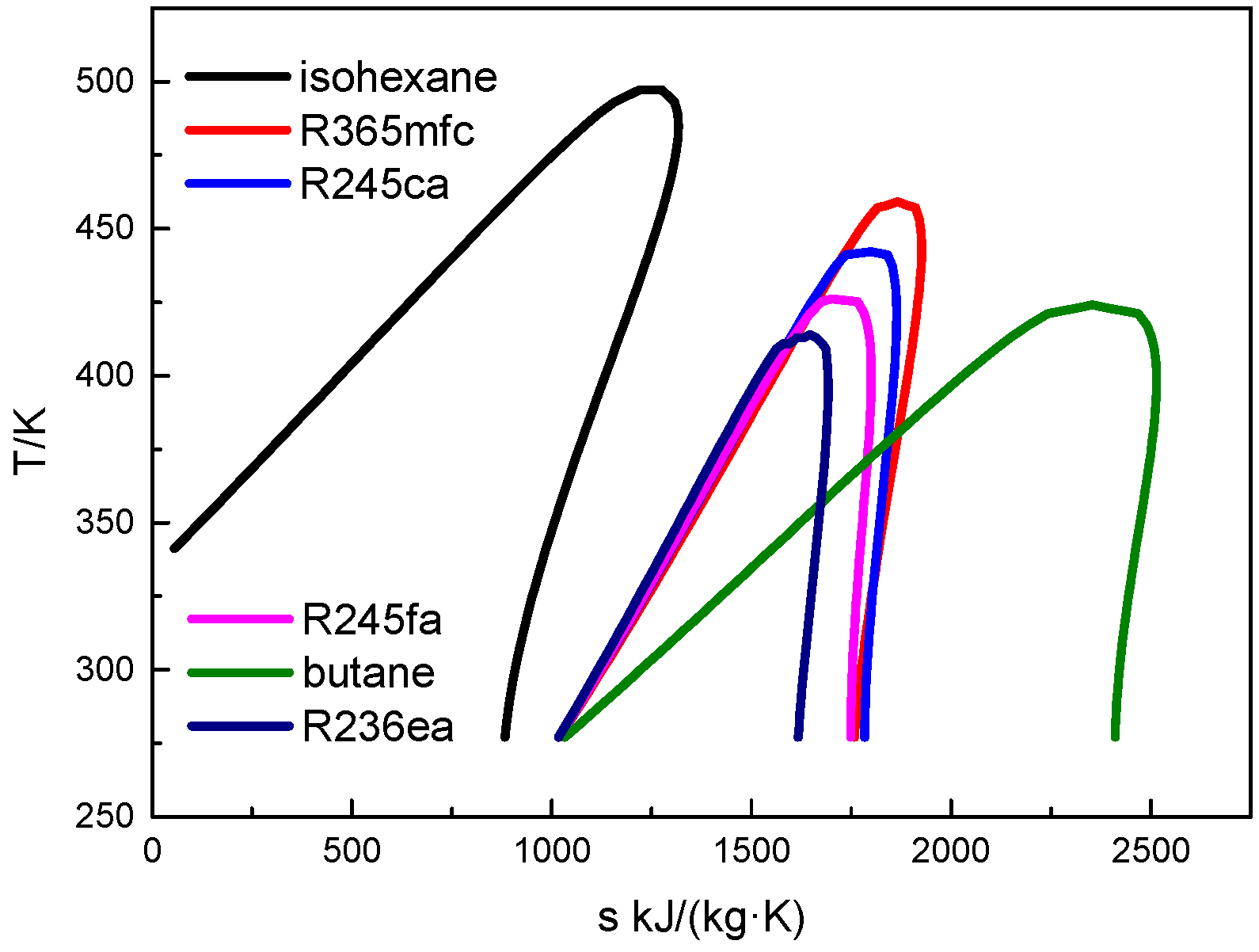
3. Working Fluid Selection and Basic Calculation Parameters

The low-grade waste flue gas is used as heat source to drive the regenerative ORC system. The waste flue gas parameters and other basic simulation conditions are summarized in Table 2.
The organic working fluids are of key importance in the regenerative ORC system, which has a significant influence on the optimal achievable performance. Six working fluids: R236ea, butane, R245fa, R245ca, R365mfc, and isohexane with an increasing critical temperature have been selected as working fluid candidates, and their characteristics are shown in Table 3. The thermodynamic properties of working fluids are taken from the REFPROP 8.0 (NIST, Gaithersburg, MD, USA) software developed by National Institute of Standards and Technology [53]. Figure 3 shows the T–s plots of the selected working fluids. The six working fluids have zero ozone depletion potential, and the autoignition temperatures of isohexane and butane are higher than the waste heat flue gas temperature.

4. Results and Discussion

In this section, the influences of evaporation temperature and degree of superheat on the system performance are evaluated. 5 °C is selected as calculation step in the optimization process. The net power output, thermal efficiency, heat recovery efficiency, VFR, specific net power output, total capital cost in 2014, SIC and LEC are calculated to select a suitable working fluid and optimize the operation parameters. For the source of waste heat, adding the evaporator to the exhaust stack will increase the back pressure, and the increasing value is about 300–600 Pa [32] which is only 0.29–0.59% of atmospheric pressure. The increment of blower power to circulate the exhaust is much less than the power consumed by the pump. Therefore, the effect of adding the ORC on the source of the waste heat is neglected in this paper.

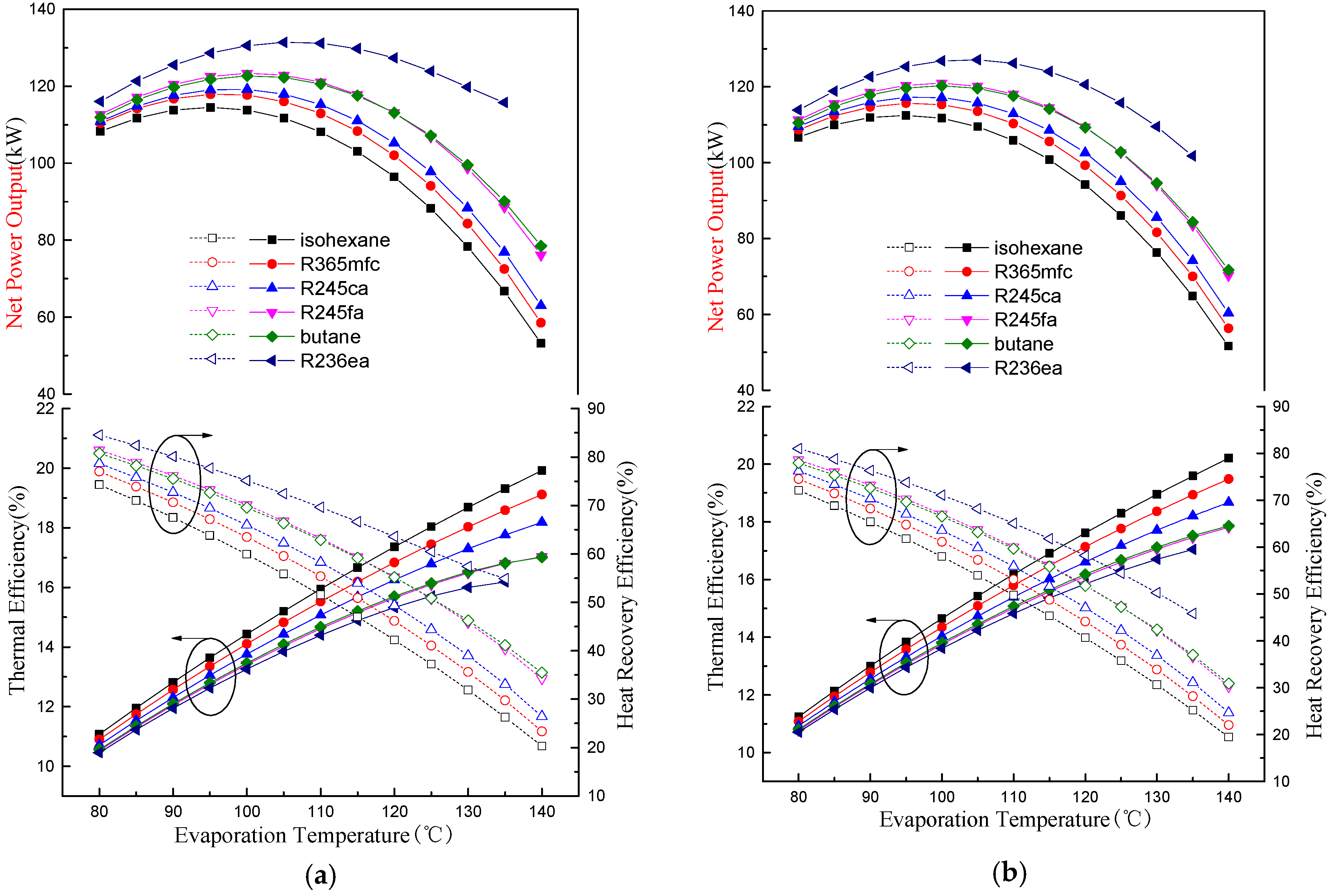
4.1. Thermodynamic Performance Analysis

Figure 4 presents the variation trends of the net power output, thermal efficiency, and heat recovery efficiency with the evaporation temperature at four different degrees of superheat conditions. The regenerative ORC system net power output is the product of the enthalpy gradient in the turbine and the working fluid mass flow rate. At each given degree of superheat, an increment in evaporation temperature results in a higher pressure drop between the turbine inlet and outlet, and the enthalpy gradient in the turbine increases accordingly. However, the mass flow rate of working fluid decreases as the evaporation temperature increases, as shown in Figure 5. Thus, the combined effect of increasing the enthalpy gradient and decreasing the mass flow rate of the working fluid will lead to a curve that has a maximum point of net power output as shown in Figure 4. According to Equation (28), the variation trends of the net power output curve can also be explained through comparing the slope between the thermal efficiency curves and heat recovery efficiency curves. The thermal efficiency generally increases while the heat recovery efficiency decreases with increment in evaporation temperature. In addition, as the evaporation temperature increases, the slope of thermal efficiency curves reduces but that of heat recovery efficiency curves increases. In the low evaporation temperature range, the slope of the thermal efficiency curves is greater than that of heat recovery efficiency curves, thus the net power output increases. As the evaporation temperature increases, the slope of thermal efficiency curves and heat recovery efficiency curves equal each other, hence partial derivatives of the product of thermal efficiency and heat recovery efficiency (Φ·ηthe) to the evaporation temperature become zero, and then the maximum net power output is obtained. The slope of the heat recovery curves is greater than that of thermal efficiency curves as the evaporation temperature increases further, and therefore the net power output is reduced.
With an increment in the degree of superheat, the enthalpy gradient in the turbine increases while the mass flow rate of the working fluid decreases, as shown in Figure 5. The enthalpy gradient increases slower than the decrease in mass flow rate, and thus the net power output decreases with the increase of degree of superheat. Additionally, the net power output curves become flatter as the degree of superheat increases, which is conducive to improving operational stability.
As mentioned above, an increment in evaporation temperature or degree of superheat leads to a decrease in mass flow rate of working fluids, as shown in Figure 5. Therefore, the temperature of waste flue gas at the evaporator outlet increases due to the limitation of pinch point temperature difference. According to Equation (27), the heat recovery efficiency decreases accordingly.
It can also be found that under the same operation conditions, the higher critical temperature of working fluids is, the higher thermal efficiency will be obtained, which is consistent with the previous studies carried out by Liu et al. [14] and Aljundi [15]. The reason lies in the fact that the higher the critical temperature of working fluids is, the greater latent the heat of evaporation becomes. The working fluid latent heat coefficient (δH) becomes larger accordingly, as shown in Figure 6. It is worthwhile noting that thermal efficiency acts as an increasing function of the latent heat coefficient according to Equation (26). Therefore, as the critical temperature of working fluid increases, the latent heat coefficient increases and the thermal efficiency simultaneously rises.
The VFR is an important parameter for the turbine, which has a major impact on the turbine isentropic efficiency and dimensions. Built-in VFR refers to the VFR under nominal working conditions, and the turbine will be manufactured according to this value. A low built-in VFR is desirable since it is advantageous to improve the mass flow rate of working fluid through the turbine, and the leakage loss decreases accordingly [54]. Furthermore, a lower built-in VFR is conducive to reduce the structural complexity and the manufacturing costs of the turbine. However, a too-low built-in VFR will lead to the turbine exhaust vapor at a high pressure state, hence the under-expansion phenomenon of working fluid appears in the turbine. As a result, the system irreversibility increases and thermal efficiency reduces. A high built-in VFR needs a large variation rate of rotor blade height between the inlet and outlet, and manufacturing costs and difficulties increase [40]. Therefore, a moderate VFR which achieves a tradeoff between lower structural complexity and less under-expansion irreversibility is essential [39]. Figure 7 displays the variations of VFR with evaporation temperature at four different degrees of superheat conditions. In order to validate the correctness and reliability of the VFR calculation results, the VFR values of isohexane, R365mfc, R245ca, R245fa, and butane (R600) with 0 °C degree of superheat were compared with their respective results in Li and Ren [39]. A good agreement between the present VFR values and the results of Li and Ren [39] was noted. VFR = 8.0 represented by dashed lines as shown in Figure 7 was taken as a reference value [39], and the VFR values of the selected working fluids should not exceed it much more.
Since the condensing temperature is given in the regenerative ORC system, the condensing pressure is constant for each working fluid. Additionally, the evaporation pressure increases with the evaporation temperature. Therefore, the VFR increases with evaporation temperature, as shown in Figure 7. With the degree of superheat increasing, the variation rate of VFR with evaporation temperature reduces slightly, which improves the operational stability under off-design operating conditions. As can be seen from Figure 7, butane has the lowest VFR and VFR increase rate among the six working fluids.
It can be observed from Figure 4 that there is an optimal evaporation temperature producing the maximum net power output, and the optimal evaporation temperature for all working fluids is between about 95 and 100 °C. In addition, the VFR of all working fluids except isohexande and R365mfc is less than 8 within this temperature range. Therefore, taking the evaporation temperature at 95 °C and 100 °C as examples, the specific net power output is depicted as in Figure 8 to compare the working capacities of different working fluids objectively. Evidently, the specific net power output of isohexane and butane is much greater than the other four working fluids. This can be explained by the fact that the latent heat of these two working fluids is much greater than the other four at the same evaporation temperature, as shown in Table 4. Therefore, the mass flow rates of both isohexane and butane are far less than those of the remaining four working fluids in the identical heat source conditions, as shown in Figure 5. Taking butane and R236ea as examples, the mass flow rate of butane is less than half of that of R236ea in the same operational conditions, while the net power output difference between these two working fluids is within 25%. Thus, the specific net power output of butane is much greater than that of R236ea. It can also be noticed that there is a slight improvement in specific net power output with an increment of the degree of superheat. This is mainly due to the fact that an increase in the degree of superheat results in an increment of enthalpy gradient in the turbine.
Figure 9 shows the total exergy destruction rate for different working fluids at a 95 °C and 100 °C evaporation temperature. It is shown that the total exergy destruction rate decreases with the increasing degree of superheat. It can be explained by the fact that the temperature difference between the heat source and working fluid narrows with the increasing degree of superheat, which reduces the exergy destruction rate in the evaporator. Additionally, the increasing of the degree of superheat allows mass flow rate to decrease. These two factors result in lower total exergy destruction. The total exergy destruction rate also decreases with the increasing of evaporation temperature as shown in Figure 9.

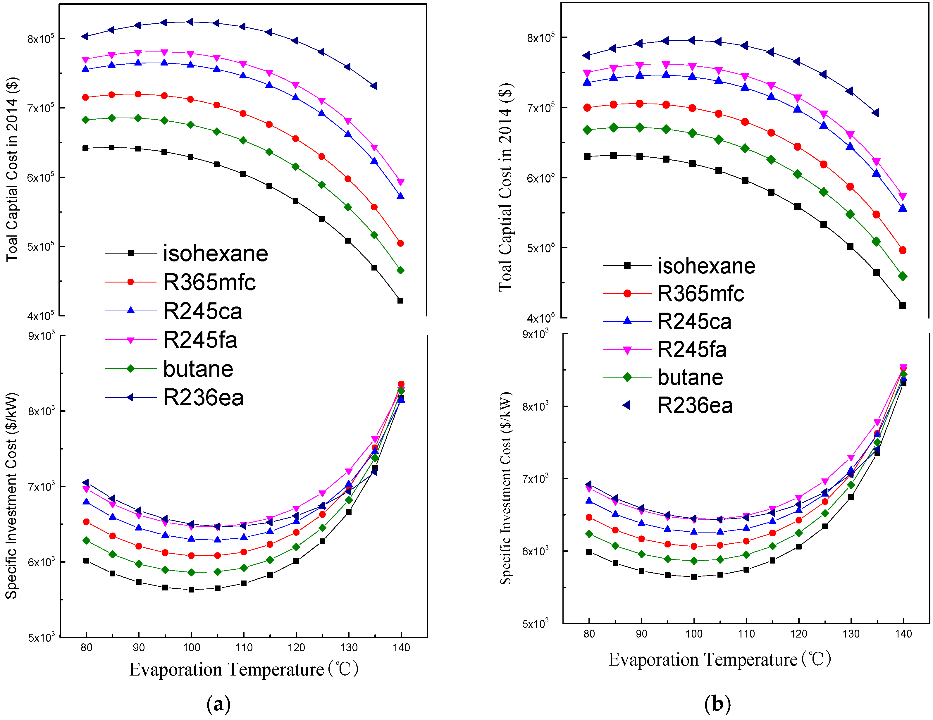
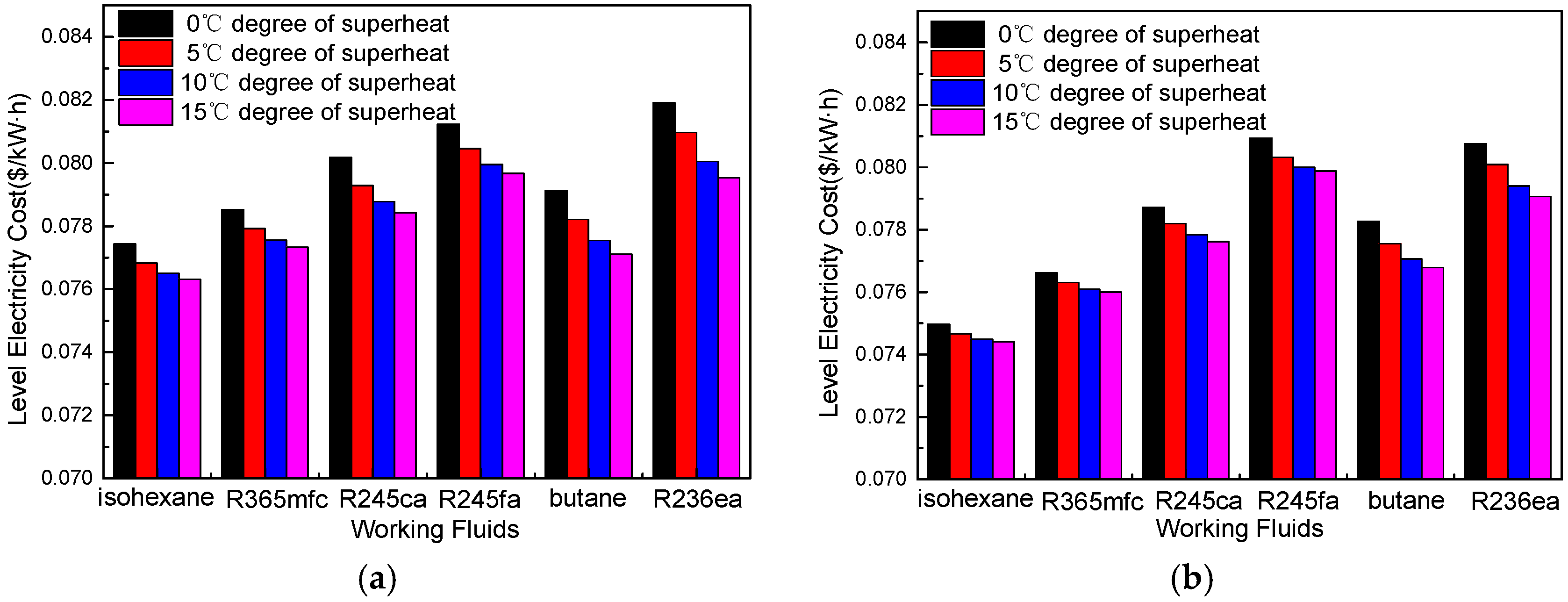
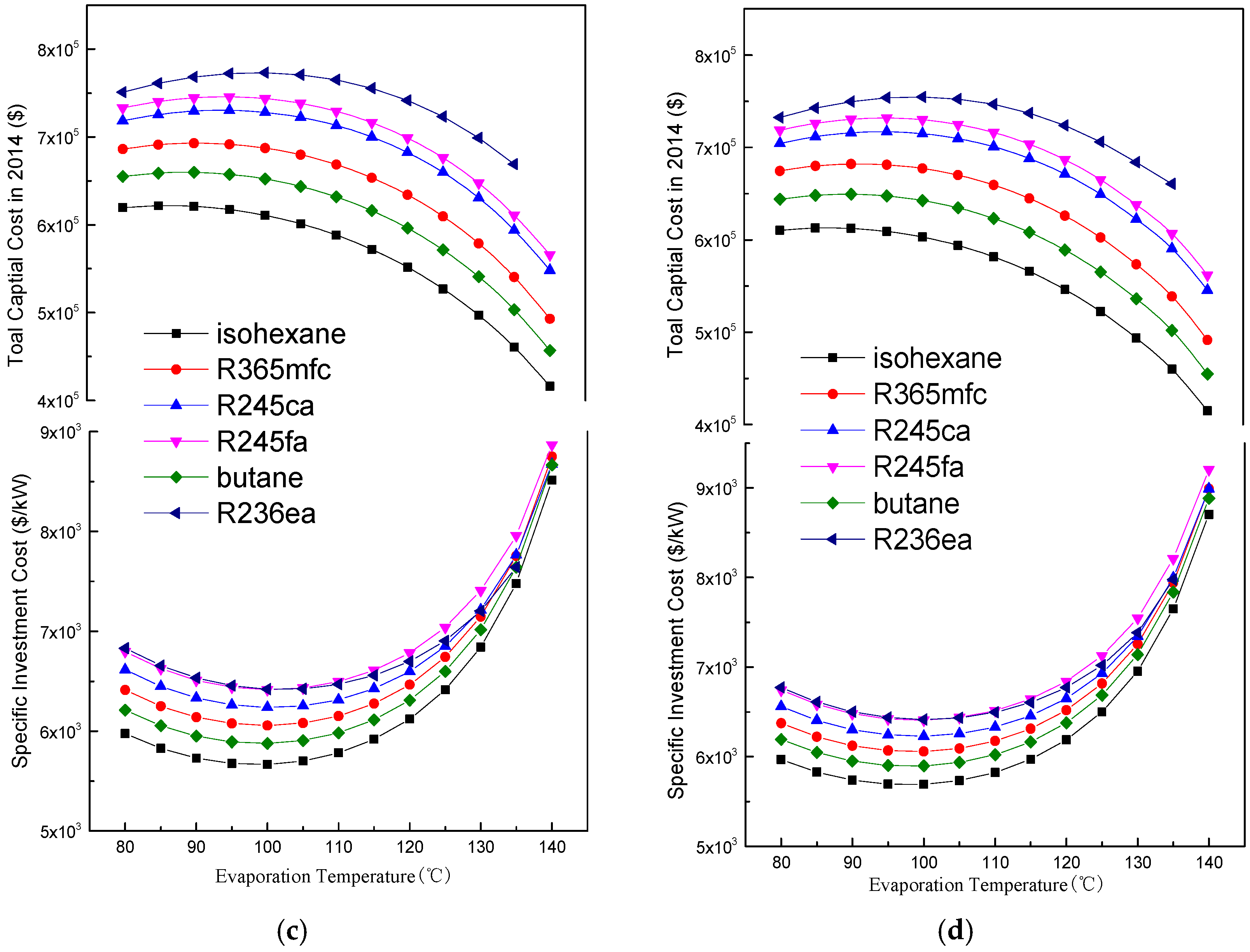
4.2. Economic Performance Analysis

Figure 10 depicts the variations of total capital cost and specific investment cost (SIC) with the evaporation temperature using four different degrees of superheat conditions. First, the total capital cost increases slightly with the evaporation temperature, and then it reaches a maximum. Finally, the total capital cost decreases with the evaporation temperature. In the low evaporation temperature range, the net power output increases with the evaporation temperature as shown in Figure 4. According to Equation (38), the capital cost of turbine increases. The mass flow rate of the working fluid decreases as the evaporation temperature increases as shown in Figure 5. The required heat exchanger area is reduced. Therefore, the capital cost of the heat exchanger decreases. In the low evaporation temperature range, the increase in capital cost of the turbine is slightly faster than the decrease in capital cost of the heat exchanger, and thus the total capital cost increases slightly with the evaporation temperature. As the evaporation temperature increases, the net power output starts to decrease, and the capital cost of turbine decreases accordingly. Therefore, the total capital cost decreases with the increment of the evaporation temperature. As the degree of superheat increases, both the net power output and mass flow rate decrease, and thus the total capital cost decrease accordingly.
In the evaluation of the specific investment cost (SIC) in the ORC system, as the evaporation temperature increases, the values of SIC first are reduced for these working fluids, reaching a minimum at certain evaporation temperatures. Then, the SIC tends to increase at a relatively higher evaporation temperature. It is noteworthy that both the net power output and the total capital cost decrease with an increasing degree of superheat. Moreover, the decrease in net power output is slower than that of the total capital cost for smaller evaporation temperature. Thus, the SIC decreases with an increment in the degree of superheat in smaller evaporation temperatures. However, at a higher evaporation temperature, the decrease in net power output is faster than that of the total capital cost. Thus, the SIC increases with the increment in degree of superheat for higher evaporation temperature. It is obvious that isohexane and butane have smaller values of SIC due to their low total capital cost.
Level electricity cost is an efficient criterion for evaluating the regenerative ORC system economic performance. It can be observed from Figure 10 that there is an optimal evaporation temperature giving a minimum SIC, and all working fluid optimal evaporation temperatures are between about 95 °C and 100 °C. Figure 11 presents variation of LEC with degree of superheat for six working fluids at 95 °C and 100 °C evaporation temperatures, respectively. Obviously, the LEC of the six working fluids has the same behavior, decreasing with the increment of degree of superheat. Furthermore, the decreasing rate decreases gradually. The maximum reduction of LEC is obtained with degrees of superheat ranging from 0 °C to 5 °C. The six working fluids, ordered in accordance with LECs from highest to lowest, are as follows: R236ea, R245fa, R245ca, butane, R365mfc, and isohexane.

4.3. Suitable Working Fluids and Optimal Parameters

Working fluid selection is a cumbersome process since there is no general criterion for evaluating the working fluid properties and its ORC system performance. As for working fluid selection and parameter optimization, not only thermodynamic and economic performance but also VFR limitation should be considered. Therefore, a fuzzy multi-criteria evaluation method is adopted to select a suitable working fluid, and the criteria weights are determined using entropy weight [55,56,57]. The net power output, specific net power output, total exergy destruction rate, VFR, total capital cost, and LEC are selected as criteria. Taking the evaporation temperature at 100 °C as example, the six working fluids are compared using the fuzzy multi-criteria evaluation method. The criteria weights are determined using entropy weight according to the following steps:
Step 1: Normalize the evaluation criteria value to obtain the evaluation matrix R = (rij)n*m.
Step 2: Calculate the proportion of criteria j of each working fluid i p ij = r ij / i = 1 m r ij .
Step 3: Calculate the entropy sj and the entropy weight wj of the jth criteria.
s j = 1 ln n i = 1 m p ij ln p ij
w j = ( 1 s j ) j = 1 n ( 1 s j )
Step 4: Calculate the evaluation matrixes for different working fluids at each degree of superheat.
B = ( w 1 ,   w 2 ,     w n ) × [ r 11 r 12 r 1 m r 21 r 22 .... r 2 m .... .... r n 1 r n 2 .... r nm ]
Assume that the i corresponding to different working fluids, and the isohexane, R365mfc, R245ca, R245fa, butane, and R236ea are numbered 1, 2, 3, 4, 5, and 6 respectively. Assume that the j corresponding to different evaluation criteria, and the net power output, specific net power output, total exergy destruction rate, VFR, total capital cost, and LEC are numbered 1, 2, 3, 4, 5, and 6 respectively. The evaluation matrixes for different working fluids are: 0 °C degree of superheat: B0 = [0.573, 0.336, 0.271, 0.250, 0.798, 0.259]; 5 °C degree of superheat: B5 = [0.581, 0.334, 0.282, 0.265, 0.814, 0.266]; 10 °C degree of superheat: B10 = [0.571, 0.316, 0.288, 0.288, 0.844, 0.285]; 15 °C degree of superheat: B15 = [0.573, 0.309, 0.293, 0.301, 0.861, 0.290];
It can be seen that the fifth working fluid (butane) is more suitable for the regenerative ORC system than other working fluids. As shown in Figure 4, the thermal efficiency of butane is lower than that of isohexane, R365mfc, and R245ca, while its heat recovery efficiency is higher than for these three working fluids. A good tradeoff is obtained between the thermal efficiency and heat recovery efficiency, making the net power output of butane keep a high level. The ‘high thermal efficiency, low net power output’ phenomenon in the conventional working fluids selection process is avoided successfully. The VFR of butane is the lowest among the six working fluids at the same evaporation temperature; additionally, its VFR variation rate is the lowest as well. Both characteristics not only reduce the difficulty of turbine design and manufacture, but also improve the operational stability. Compared with remaining working fluids, the low VFR of butane can enlarge the operation range of evaporation temperature under the same VFR limitations (dashed lines as depicted in Figure 7). As far as specific net power output is concerned, butane has a slightly lower output than isohexane, while it is much greater than that of R365mfc, R245ca, R245fa, and R236ea, which indicates its superior working capacity. Butane has the lowest total exergy destruction among the selected working fluids. In terms of economic performance, butane has the second smallest total capital cost and SIC among the six working fluids. As far as LEC, butane is superior to R245ca, R245fa, and R236ea but is inferior to isohexane and R365mfc. As for net power output, specific net power output, total exergy destruction rate, VFR, total capital cost, and LEC, butane is not able to attain every single criterion optimum value simultaneously. However, a reasonable compromise is attained by butane, leading to it obtaining a better comprehensive performance among the six working fluids. The optimum evaporation temperature for butane is 100 °C.
The fuzzy multi-criteria evaluation method is also adopted to determine the optimal degree of superheat. i corresponds to different degree of superheat, and 0, 5, 10, and 15 °C are numbered 1, 2, 3, and 4, respectively. The evaluation criteria are not changed. The evaluation matrixes of butane for different degrees of superheat are [0.649, 0.828, 0.432, 0.272]. It is obvious that the 5 °C degree of superheat (the second) is more suitable for butane. A slight degree of superheat is conducive to an improvement of the ORC system’s comprehensive performance. The net power output decreases, while thermal efficiency and specific net power output increase with the increment in degree of superheat. Therefore, a proper degree of superheat is beneficial to improving the working capacity of working fluids. Superheat is also conducive to reducing the total exergy destruction rate. As mentioned above, the increase in degree of superheat results in a decrease in VFR and its variation rate. Therefore, a proper degree of superheat not only reduces the difficulty in turbine design and manufacture, but also improves the operational stability under off-design operating conditions. Superheat reduces the total capital cost, SIC, and LEC as well, improving system economic performance.

5. Conclusions

Based on thermodynamic and economic performance, simultaneously considering the limitations of VFR and the effect of superheat, the working fluid selection and parameter optimization have been investigated with respect to a regenerative ORC system. The optimization of the evaporation temperature is carried out by analyzing the variation of net power output and specific investment cost (SIC). Then, the net power output, specific net power output, total exergy destruction rate, VFR, total capital cost, and LEC are selected as criteria, and a fuzzy multi-criteria evaluation method is adopted to select a more suitable working fluid and determine the optimal degree of superheat. The main conclusions drawn from the present study are summarized as follows:
(1)
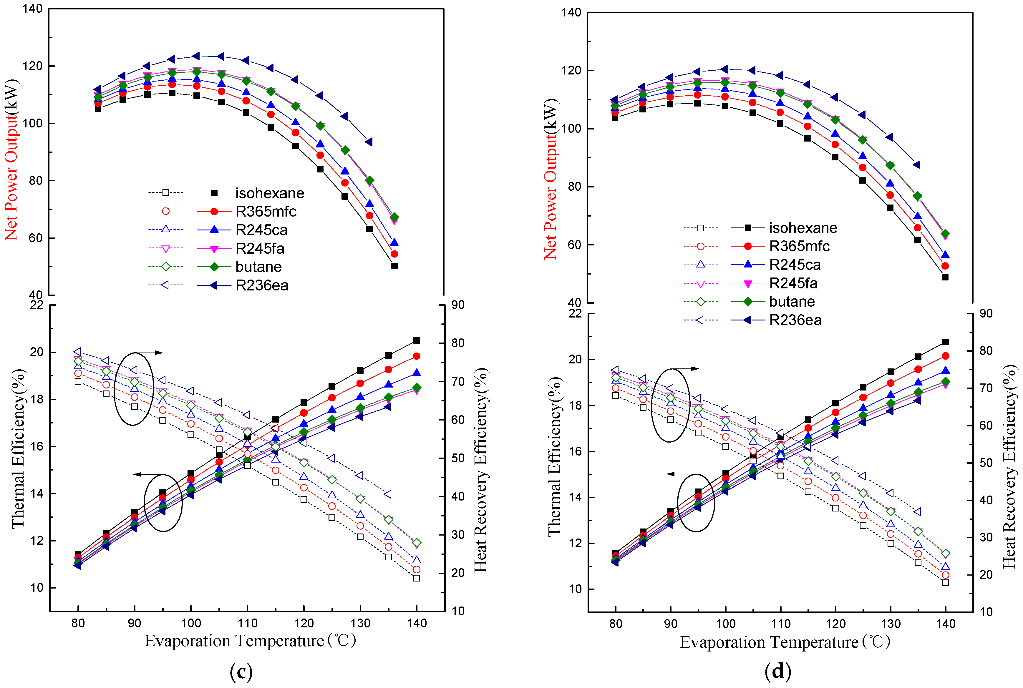
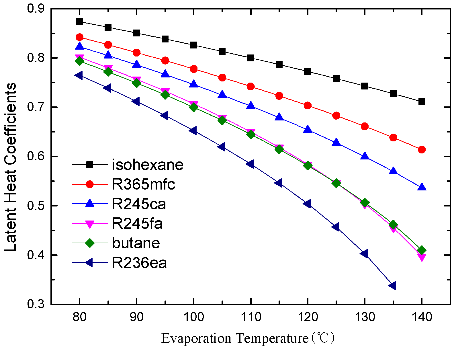
There is an optimal evaporation temperature giving a maximum net power output and a minimum SIC. The specific net power output of isohexane and butane is much greater than the other four working fluids due to their greater latent heat.
(2)
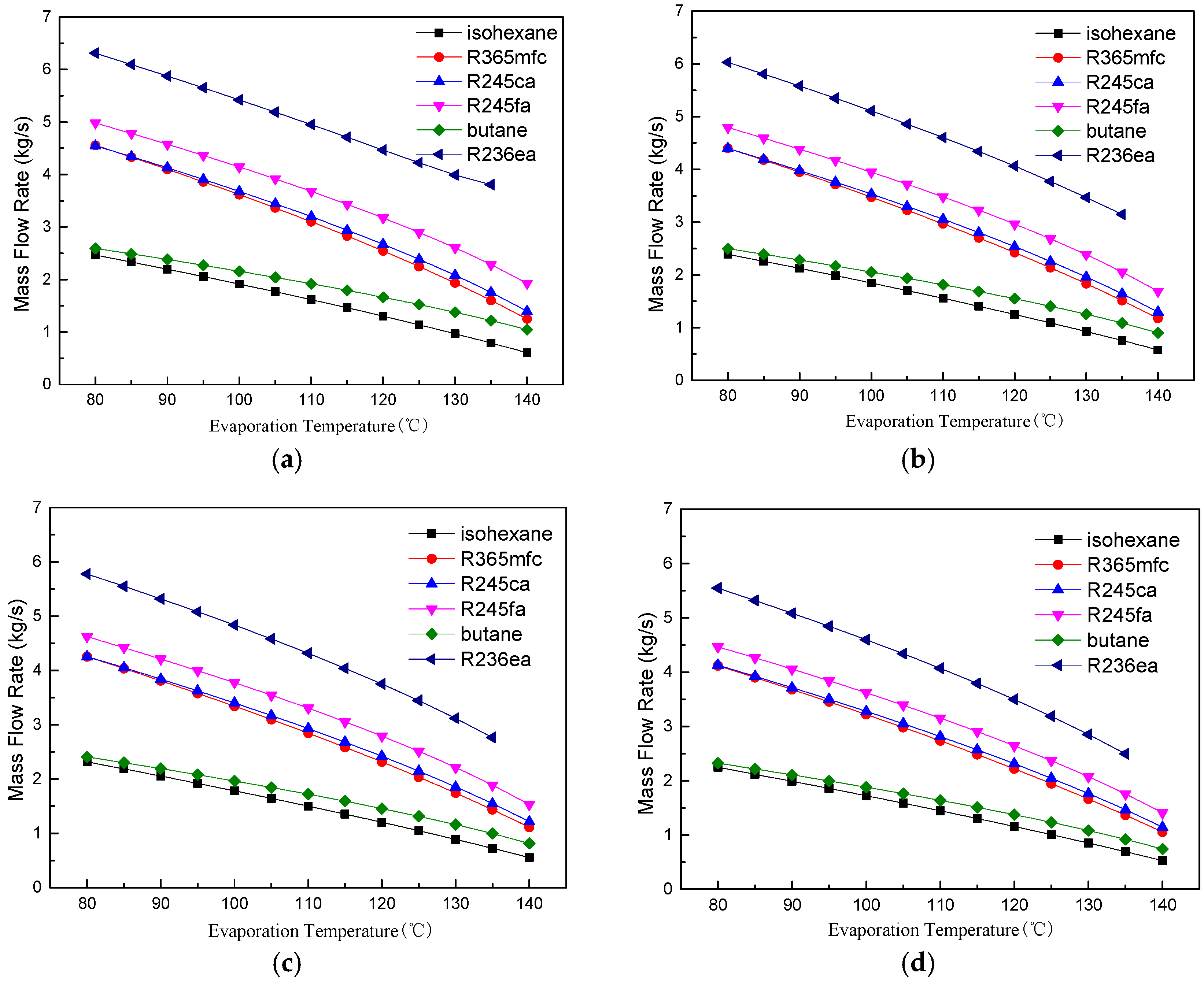
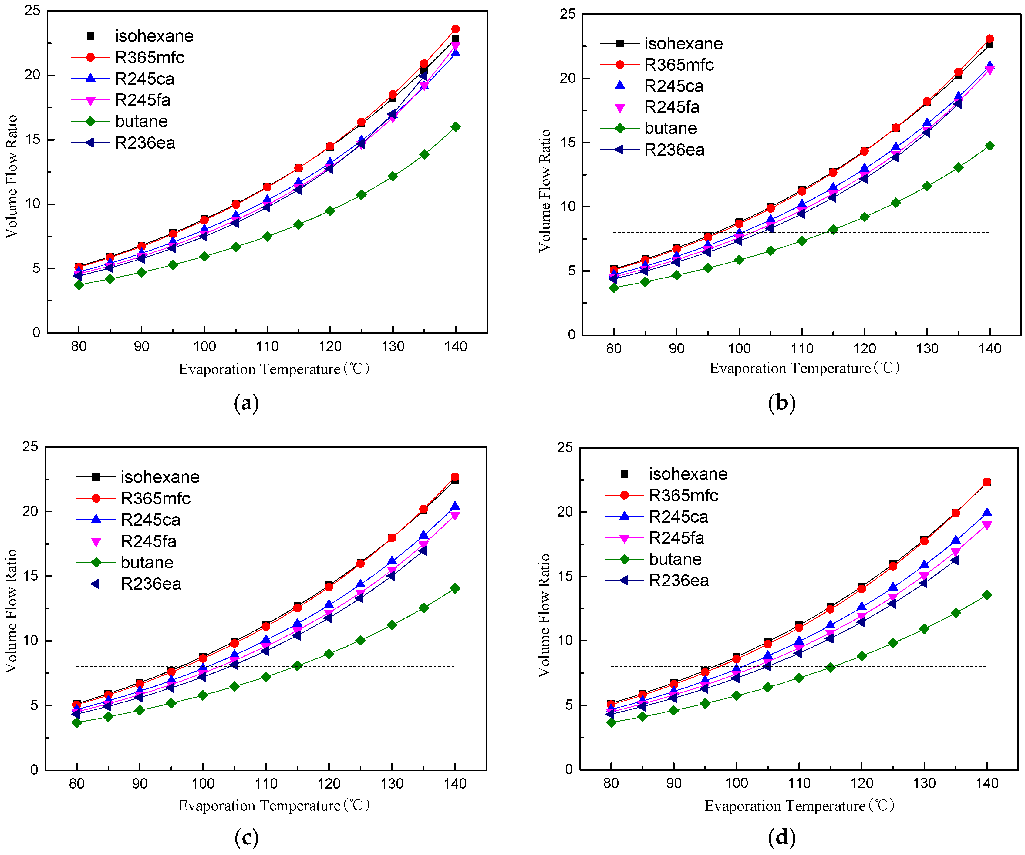
The evaporation temperature operation range is affected by the VFR. Butane has the lowest VFR and the largest evaporation temperature operation range among the six working fluids.
(3)
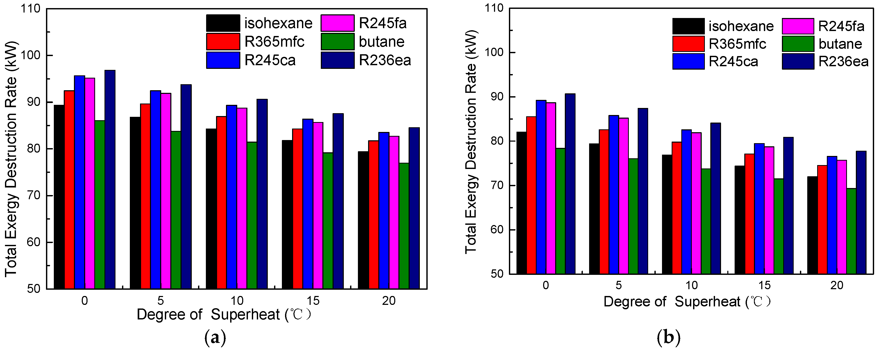
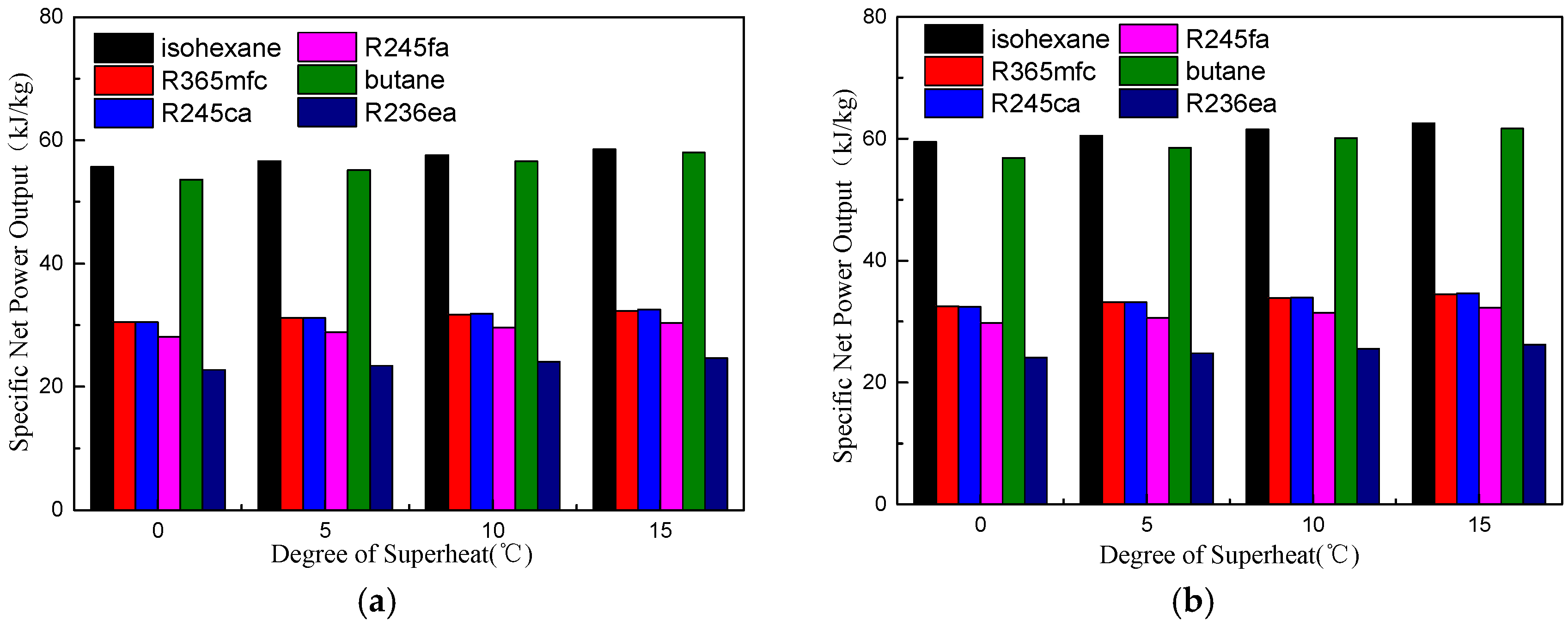
A suitable degree of superheat is necessary since it is not only conducive to improving the working capacity of working fluids, but also reduces the total exergy destruction rate, VFR, total capital cost, SIC, and LEC for different working fluids. The system’s thermodynamic and economic performance, as well as the operational stability, are improved.
(4)
Compared with other working fluids, butane shows the best comprehensive performance for the regenerative ORC system. Furthermore, the optimal evaporation temperature and degree of superheat are 100 °C and 5 °C, respectively.

Acknowledgments

The authors would like to thank the National Natural Science Foundation of China (51306059), National Science and Technology Support Program of China (2014BAA06B01), and Fundamental Research Funds for the Central Universities (2017XS120).

Author Contributions

All authors contributed to this work. Peng Li is the main author of this work. Zhonghe Han guided the analysis and the writing of the paper. Xu Han and Zhongkai Mei assisted with the modeling. Zhi Wang provided suggestions with respect to article modification.

Conflicts of Interest

The authors declare no conflict of interest.

Abbreviations

CEPCIChemical engineering plant cost index
ComOperation and maintenance cost
CRFCapital recovery cost
GWPGreenhouse warming potential
LECLevel energy cost
NPVNet present value
NSGA-IINon-dominated sorting genetic algorithm II
ODPOzone depletion potential
ORCOrganic Rankine Cycle
PBPPayback period
SICSpecific investment cost
TopSystem operation time
VFRVolume flow ratio
Nomenclature
aThermal diffusivity
AArea (m2)
BEvaluation matrixes
CInvestment cost ($)
CbBasic cost of each equipment ($)
CBMBare module equipment cost ($)
cpSpecific heat (kJ/kg·K)
dDiameter (m)
FbmAggregate multiplication
FmMaterial factor
FpPressure factor
hSpecific enthalpy (kJ/kg)
iInterest rate
IExergy destruction rate (kW)
K1, K2, K3, B1, B2, C1, C2, C3Constant coefficients for cost evaluation
mMass flow rate (kg/s)
NuNusselt number
p
PPressure
p*Reduced pressure
PnetSpecific net power output (kJ/kg)
PrPrandtl number
qHeat flux density (J/m2·s)
QHeat transfer rate (kW)
ReReynolds number
sEntropy (kJ/kg·K); Shannon Entropy
TTemperature (°C)
TopSystem operation time
TsSaturation temperature (°C)
TyPlant life time
UOverall heat transfer coefficient (W/m2·K)
vSpecific volume (m3/kg)
wEntropy weight
WPower work (kW)
xVapor mass quality
Subscripts
1-6State points corresponding to Figure 1 and Figure 2
1b, 1d, 2s, 4d, 5s, a-gState points corresponding to Figure 2
ambAmbient
conCondenser
evaEvaporator
fWorking fluid
gGaseous
gasWaste flue gas
HHeat source
IHEInternal heat exchanger
iDifferent regions in heat exchanger
inInlet; inside
lLiquid
LCold source
maxMaximum
minMinimum
netNet
outOutlet; outside
pPump
sIsentropic
supSuperheated vapor
TotalTotal exergy destruction rate
TTurbine
theThermal
Greek Letters
αHeat transfer coefficient (W/m2·K)
γHLatent heat (kJ/kg)
δHLatent heat coefficient
δIHEInternal heat coefficient
δlPreheating coefficient
δsupSuperheating coefficient
εEffectiveness of internal heat exchanger
ηEfficiency
λThermal conductivity(W/m·K)
μViscosity (m2/s)
ρDensity (kg/m3)
ΔTmLogarithmic mean temperature (°C)

References

  1. Feng, Y.Q.; Hung, T.C.; He, Y.L.; Wang, Q.; Wang, S.; Li, B.X.; Lin, J.R.; Zhang, W. Operation Characteristic and Performance Comparison of Organic Rankine Cycle (ORC) for Low-grade Waste Heat Using R245fa, R123 and Their Mixtures. Energy Convers. Manag. 2017, 144, 153–163. [Google Scholar] [CrossRef]
  2. Javanshir, A.; Sarunac, N.; Razzaghpanah, Z. Thermodynamic Analysis of a Regenerative Organic Rankine Cycle Using Dry Fluids. Appl. Therm. Eng. 2017, 123, 852–864. [Google Scholar] [CrossRef]
  3. Girgin, I.; Ezgi, C. Design and Thermodynamic and Thermoeconomic Analysis of an Organic Rankine Cycle for Naval Surface Ship Applications. Energy Convers. Manag. 2017, 148, 623–634. [Google Scholar] [CrossRef]
  4. Dai, Y.; Wang, J.; Gao, L. Parametric Optimization and Comparative Study of Organic Rankine Cycle (ORC) for Low Grade Waste Heat Recovery. Energy Convers. Manag. 2009, 50, 576–582. [Google Scholar] [CrossRef]
  5. Xu, G.; Song, G.; Zhu, X.; Gao, W.; Li, H.; Quan, Y. Performance Evaluation of a Direct Vapor Generation Supercritical ORC System Driven by Linear Fresnel Reflector Solar Concentrator. Appl. Therm. Eng. 2015, 80, 196–204. [Google Scholar] [CrossRef]
  6. Liu, Z.; Xu, W.; Qian, C.; Chen, X.; Jin, G. Investigation on the Feasibility and Performance of Ground Source Heat Pump (GSHP) in Three Cities in Cold Climate Zone, China. Renew. Energy 2015, 84, 89–96. [Google Scholar] [CrossRef]
  7. Ceperley, P.H. A Pistonless Stirling Engine—The Traveling Wave Heat Engine. J. Acoust. Soc. Am. 1979, 66, 1508–1513. [Google Scholar] [CrossRef]
  8. Markides, C.N.; Smith, T.C.B. A Dynamic Model for the Efficiency Optimization of an Oscillatory Low Grade Heat Engine. Energy 2011, 36, 6967–6980. [Google Scholar] [CrossRef]
  9. Kirmse, C.J.W.; Oyewunmi, O.A.; Haslam, A.J.; Markides, C.N. Comparison of a Novel Organic-fluid Thermofluidic Heat Converter and an Organic Rankine Cycle Heat Engine. Energies 2016, 9, 47. [Google Scholar] [CrossRef]
  10. Roy, J.; Mishra, M.; Misra, A. Performance Analysis of an Organic Rankine Cycle with Superheating under Different Heat Source Temperature Conditions. Appl. Energy 2011, 88, 2995–3004. [Google Scholar] [CrossRef]
  11. Roy, J.; Misra, A. Parametric Optimization and Performance Analysis of a Regenerative Organic Rankine Cycle Using R-123 for Waste Heat Recovery. Energy 2012, 39, 227–235. [Google Scholar] [CrossRef]
  12. Chen, Q.; Xu, J.; Chen, H. A New Design Method for Organic Rankine Cycles with Constraint of Inlet and Outlet Heat Carrier Fluid Temperatures Coupling with the Heat Source. Appl. Energy 2012, 98, 562–573. [Google Scholar] [CrossRef]
  13. Gao, W.; Li, H.; Xu, G.; Quan, Y. Working Fluid Selection and Preliminary Design of a Solar Organic Rankine Cycle System. Environ. Prog. Sustain. Energy 2015, 34, 619–626. [Google Scholar] [CrossRef]
  14. Liu, B.T.; Chien, K.H.; Wang, C.C. Effect of Working Fluids on Organic Rankine Cycle for Waste Heat Recovery. Energy 2004, 29, 1207–1217. [Google Scholar] [CrossRef]
  15. Aljundi, I.H. Effect of Dry Hydrocarbons and Critical Point Temperature on the Efficiencies of Organic Rankine Cycle. Renew. Energy 2011, 36, 1196–1202. [Google Scholar] [CrossRef]
  16. Li, J.; Alvi, J.Z.; Pei, G.; Ji, J.; Li, P.; Fu, H. Effect of Working Fluids on the Performance of a Novel Direct Vapor Generation Solar Organic Rankine Cycle System. Appl. Therm. Eng. 2016, 98, 786–797. [Google Scholar] [CrossRef]
  17. Invernizzi, C.; Iora, P.; Silva, P. Bottoming Micro-Rankine Cycles for Micro-gas Turbines. Appl. Therm. Eng. 2007, 27, 100–110. [Google Scholar] [CrossRef]
  18. Larjola, J. Electricity from Industrial Waste Heat Using High-speed Organic Rankine Cycle (ORC). Int. J. Prod. Econ. 1995, 41, 227–235. [Google Scholar] [CrossRef]
  19. Wu, S.; Li, C.; Xiao, L.; Liu, C.; Li, Y. A Comparative Study on Thermo-economic Performance between Subcritical and Transcritical Organic Rankine Cycles under Different Heat Source Temperatures. Chin. Sci. Bull. 2014, 59, 4379–4387. [Google Scholar] [CrossRef]
  20. Lecompte, S.; Lemmens, S.; Huisseune, H.; van den Broek, M.; De Paepe, M. Multi-objective Thermo-economic Optimization Strategy for ORCs Applied to Subcritical and Transcritical Cycles for Waste Heat Recovery. Energies 2015, 8, 2714–2741. [Google Scholar] [CrossRef] [Green Version]
  21. Wang, X.; Zhao, L. Analysis of Zeotropic Mixtures Used in Low-temperature Solar Rankine Cycles for Power Generation. Sol. Energy 2009, 83, 605–613. [Google Scholar] [CrossRef]
  22. Feng, Y.; Hung, T.; Greg, K.; Zhang, Y.; Li, B.; Yang, J. Thermoeconomic Comparison between Pure and Mixture Working Fluids of Organic Rankine Cycles (ORCs) for Low Temperature Waste Heat Recovery. Energy Convers. Manag. 2015, 106, 859–872. [Google Scholar] [CrossRef]
  23. Wu, Y.; Zhu, Y.; Yu, L. Thermal and Economic Performance Analysis of Zeotropic Mixtures for Organic Rankine Cycles. Appl. Therm. Eng. 2016, 96, 57–63. [Google Scholar] [CrossRef]
  24. Heberle, F.; Brüggemann, D. Thermo-economic Analysis of Zeotropic Mixtures and Pure Working Fluids in Organic Rankine Cycles for Waste Heat Recovery. Energies 2016, 9, 226. [Google Scholar] [CrossRef]
  25. Desai, N.B.; Bandyopadhyay, S. Process Integration of Organic Rankine Cycle. Energy 2009, 34, 1674–1686. [Google Scholar] [CrossRef]
  26. Saleh, B.; Koglbauer, G.; Wendland, M.; Fischer, J. Working Fluids for Low-temperature Organic Rankine Cycles. Energy 2007, 32, 1210–1221. [Google Scholar] [CrossRef]
  27. Li, W.; Feng, X.; Yu, L.; Xu, J. Effects of Evaporating Temperature and Internal Heat Exchanger on Organic Rankine Cycle. Appl. Therm. Eng. 2011, 31, 4014–4023. [Google Scholar] [CrossRef]
  28. Liu, Q.; Duan, Y.; Yang, Z. Performance Analyses of Geothermal Organic Rankine Cycles with Selected Hydrocarbon Working Fluids. Energy 2013, 63, 123–132. [Google Scholar] [CrossRef]
  29. Tocci, L.; Pal, T.; Pesmazoglou, I.; Franchetti, B. Small Scale Organic Rankine Cycle (ORC): A Techno-Economic Review. Energies 2017, 10, 413. [Google Scholar] [CrossRef]
  30. Lemmens, S. Cost Engineering Techniques and Their Applicability for Cost Estimation of Organic Rankine Cycle Systems. Energies 2016, 9, 485. [Google Scholar] [CrossRef]
  31. Xiao, L.; Wu, S.Y.; Yi, T.T.; Liu, C.; Li, Y.R. Multi-objective Optimization of Evaporation and Condensation Temperatures for Subcritical Organic Rankine Cycle. Energy 2015, 83, 723–733. [Google Scholar] [CrossRef]
  32. Zhang, C.; Liu, C.; Wang, S.; Xu, X.; Li, Q. Thermo-economic Comparison of Subcritical Organic Rankine Cycle Based on Different Heat Exchanger Configurations. Energy 2017, 123, 728–741. [Google Scholar] [CrossRef]
  33. Heberle, F.; Brüggemann, D. Thermo-economic Evaluation of Organic Rankine Cycles for Geothermal Power Generation Using Zeotropic Mixtures. Energies 2015, 8, 2097–2124. [Google Scholar] [CrossRef]
  34. Oyewunmi, O.A.; Markides, C.N. Thermo-economic and Heat Transfer Optimization of Working-fluid Mixtures in a Low-temperature Organic Rankine Cycle system. Energies 2016, 9, 448. [Google Scholar] [CrossRef]
  35. Wang, J.; Yan, Z.; Wang, M.; Li, M.; Dai, Y. Multi-objective Optimization of an Organic Rankine Cycle (ORC) for Low Grade Waste Heat Recovery Using Evolutionary Algorithm. Energy Convers. Manag. 2013, 71, 146–158. [Google Scholar] [CrossRef]
  36. Wang, H.; Xu, J.; Yang, X.; Miao, Z.; Yu, C. Organic Rankine Cycle Saves Energy and Reduces Gas Emissions for Cement Production. Energy 2015, 86, 59–73. [Google Scholar] [CrossRef]
  37. Li, R.; Wang, H.; Yao, E.; Zhang, S. Thermo-Economic Comparison and Parametric Optimizations among Two Compressed Air Energy Storage System Based on Kalina Cycle and ORC. Energies 2016, 10, 15. [Google Scholar] [CrossRef]
  38. Patel, B.; Desai, N.B.; Kachhwaha, S.S.; Jain, V.; Hadia, N. Thermo-economic Analysis of a Novel Organic Rankine Cycle Integrated Cascaded Vapor Compression–absorption System. J. Clean. Prod. 2017, 154, 26–40. [Google Scholar] [CrossRef]
  39. Li, Y.; Ren, X.D. Investigation of the Organic Rankine Cycle (ORC) System and the Radial-inflow Turbine Design. Appl. Therm. Eng. 2016, 96, 547–554. [Google Scholar] [CrossRef]
  40. Costall, A.W.; Hernandez, A.G.; Newton, P.J.; Martinez-Botas, R.F. Design Methodology for Radial Turbo Expanders in Mobile Organic Rankine Cycle Applications. Appl. Energy 2015, 157, 729–743. [Google Scholar] [CrossRef]
  41. Feng, Y.; Zhang, Y.; Li, B.; Yang, J.; Shi, Y. Sensitivity Analysis and Thermoeconomic Comparison of ORCs (Organic Rankine Cycles) for Low Temperature Waste Heat Recovery. Energy 2015, 82, 664–677. [Google Scholar] [CrossRef]
  42. Sieder, E.N.; Tate, G.E. Heat Eransfer and Pressure Drop of Liquids in Tubes. Ind. Eng. Chem. 1936, 28, 1429–1435. [Google Scholar] [CrossRef]
  43. Kern, D.Q. Process Heat Transfer; McGraw-Hill: New York, NY, USA, 1950. [Google Scholar]
  44. Stephan, K.; Abdelsalam, M. Heat-transfer Correlations for Natural Convection Boiling. Int. J. Heat Mass Transf. 1980, 23, 73–87. [Google Scholar] [CrossRef]
  45. Shah, M.M. A General Correlation for Heat Transfer During Film Condensation Inside Pipes. Int. J. Heat Mass Transf. 1979, 22, 547–556. [Google Scholar] [CrossRef]
  46. Turton, R.; Bailie, R.C.; Whiting, W.B.; Shaeiwitz, J.A. Analysis, Synthesis and Design of Chemical Processes, 4th ed.; Pearson Education: Ann Arbor, MI, USA, 2013. [Google Scholar]
  47. Shengjun, Z.; Huaixin, W.; Tao, G. Performance Comparison and Parametric Optimization of Subcritical Organic Rankine Cycle (ORC) and Transcritical Power Cycle System for Low-temperature Geothermal Power Generation. Appl. Energy 2011, 88, 2740–2754. [Google Scholar] [CrossRef]
  48. Mignard, D. Correlating the Chemical Engineering Plant Cost Index with Macro-economic Indicators. Chem. Eng. Res. Des. 2014, 92, 285–294. [Google Scholar] [CrossRef]
  49. Nafey, A.; Sharaf, M. Combined Solar Organic Rankine Cycle with Reverse Osmosis Desalination Process: Energy, Exergy, and Cost Evaluations. Renew. Energy 2010, 35, 2571–2580. [Google Scholar] [CrossRef]
  50. El-Emam, R.S.; Dincer, I. Exergy and Exergoeconomic Analyses and Optimization of Geothermal Organic Rankine Cycle. Appl. Therm. Eng. 2013, 59, 435–444. [Google Scholar] [CrossRef]
  51. Li, Y.R.; Du, M.T.; Wu, C.M.; Wu, S.Y.; Liu, C. Potential of Organic Rankine Cycle Using Zeotropic Mixtures as Working Fluids for Waste Heat Recovery. Energy 2014, 77, 509–519. [Google Scholar] [CrossRef]
  52. Cayer, E.; Galanis, N.; Nesreddine, H. Parametric Study and Optimization of a Transcritical Power Cycle Using a Low Temperature Source. Appl. Energy 2010, 87, 1349–1357. [Google Scholar] [CrossRef]
  53. National Institute of Standards and Technology (NIST). REFPROP: Reference Fluid Thermodynamic and Transport Properties; NIST: Boulder, CO, USA, 2007.
  54. Li, J.; Li, P.; Pei, G.; Alvi, J.; Li, J. Analysis of a Novel Solar Electricity Generation System Using Cascade Rankine Cycle and Steam Screw Expander. Appl. Energy 2016, 165, 627–638. [Google Scholar] [CrossRef]
  55. Li, L.; Liu, F.; Li, C. Customer Satisfaction Evaluation Method for Customized Product Development Using Entropy Weight and Analytic Hierarchy Process. Comput. Ind. Eng. 2014, 77, 80–87. [Google Scholar] [CrossRef]
  56. Chen, T.; Jin, Y.; Qiu, X.; Chen, X. A Hybrid Fuzzy Evaluation Method for Safety Assessment of Food-waste Feed Based on Entropy and the Analytic Hierarchy Process Methods. Expert Syst. Appl. 2014, 41, 7328–7337. [Google Scholar] [CrossRef]
  57. Feng, Y.; Hung, T.C.; Zhang, Y.; Li, B.; Yang, J.; Shi, Y. Performance Comparison of Low-grade ORCs (Organic Rankine Cycles) Using R245fa, Pentane and Their Mixtures Based on the Thermoeconomic Multi-Objective Optimization and Decision Makings. Energy 2015, 93, 2018–2029. [Google Scholar] [CrossRef]
Figure 1. Schematic diagram of the regenerative Organic Rankine Cycle (ORC) system for low-temperature waste heat.
Energies 10 01593 g001
Figure 2. Typical T–s diagram for the regenerative ORC system.
Energies 10 01593 g002
Figure 3. The T–s plots of working fluids.
Energies 10 01593 g003
Figure 4. Variations of net power output, thermal efficiency, and heat recovery efficiency with evaporation temperature at four different degrees of superheat: (a) 0 °C degree of superheat; (b) 5 °C degree of superheat; (c) 10 °C of superheat; and (d) 15 °C degree of superheat.
Energies 10 01593 g004aEnergies 10 01593 g004b
Figure 5. Variations of mass flow rate with evaporation temperature at four different degrees of superheat: (a) 0 °C degree of superheat; (b) 5 °C degree of superheat; (c) 10 °C degree of superheat; and (d) 15 °C degree of superheat.
Energies 10 01593 g005
Figure 6. Latent heat coefficients of different working fluids.
Energies 10 01593 g006
Figure 7. Variations of variation flow ratio with evaporation temperature at four different degrees of superheat: (a) 0 °C degree of superheat; (b) 5 °C degree of superheat; (c) 10 °C degree of superheat; and (d) 15 °C degree of superheat.
Energies 10 01593 g007
Figure 8. Comparisons of specific net power output for different working fluids at two evaporation temperatures: (a) Evaporation temperature at 95 °C; and (b) Evaporation temperature at 100 °C.
Energies 10 01593 g008
Figure 9. Comparisons of total exergy destruction rate for different working fluids at two evaporation temperatures: (a) Evaporation temperature at 95 °C; and (b) Evaporation temperature at 100 °C.
Energies 10 01593 g009
Figure 10. Variations of total capital cost in 2014 and specific investment cost with evaporation temperature at four different degrees of superheat conditions: (a) 0 °C degree of superheat; (b) 5 °C degree of superheat; (c) 10 °C degree of superheat; and (d) 15 °C degree of superheat.
Energies 10 01593 g010aEnergies 10 01593 g010b
Figure 11. Variation of LEC with degree of superheat for six working fluids at two evaporation temperatures: (a) Evaporation temperature at 95 °C; and (b) Evaporation temperature at 100 °C.
Energies 10 01593 g011
Table 1. Coefficients required for cost evaluation of each component [46,47].
ComponentsK1K2K3C1C2C3B1B2FmFbm
Heat exchanger3.21380.26880.0796−0.06490.05020.014741.801.501.25-
Pump3.38920.05360.1538−0.39350.3957−0.00221.891.351.5-
Turbine3.51400.589000000003.50
Table 2. Waste flue gas parameters and simulation conditions assumed for the ORC System.
ItemUnitValue
Waste flue gas temperature°C160
Mass flow of waste flue gas temperaturekg·s−110
Pinch point temperature difference in evaporator°C5
Pinch point temperature difference in IHE°C5
Pinch point temperature difference in condenser°C5
Condensing temperature°C30
Cooling water inlet temperature°C20
Environmental temperature°C20
Turbine isentropic efficiency%85
Pump isentropic efficiency%85
Table 3. Properties of the six organic working fluids.
Working FluidsMolecular Weight (g·mol−1)Normal Boiling Point (°C)Critical Temperature (°C)Critical Pressure (MPa)
Isohexane86.17560.21224.553.040
R365mfc148.07540.15186.853.266
R245ca134.04925.13174.423.925
R245fa134.04815.14154.013.651
Butane58.122−0.49151.983.923
R236ea152.0396.19139.293.502
Note: Normal boiling point: boiling at 1 bar.
Table 4. Latent heat of working fluids at two evaporation temperature.
Working FluidsLatent Heat at 95 °C (kJ/kg)Latent Heat at 100 °C (kJ/kg)
Isohexane295.54291.17
R365mfc157.38154.04
R245ca155.59151.44
R245fa139.32134.48
Butane267.66258.26
R236ea107.57102.76

