Abstract
The transformer is one of the most discussed and important components of electrical power systems because of its reliability, durability and energy conversion capability. It is also useful in load sharing, which reduces system burden, but is also responsible for a sufficient number of losses, as it is used in different types of electric appliances that require voltage conversion. The no-load losses of transformers have gained much attention from research perspective because of its operating cost throughout its lifetime. Many studies were carried out to achieve the highest possible efficiency, decreasing certain losses by using different methods and materials. However, the local market in Pakistan is far behind in the field of efficient core material manufacturing of transformers, which is why consumers are unable to obtain efficient electric appliances. Due to these loss-making appliances, the overall residential load increases and the consumers are charged with heavy electricity bills. This proposed study discusses core losses, different core comparisons, T/F efficiency and advancement in the core material. To accomplish a core comparison, two locally available core materials are used to fabricate two different T/F, and some tests such as open-circuit and short-circuit tests are performed to discover their losses, thermal degradation, and output efficiencies.
1. Introduction
For the last few decades, the demand for electric energy has increased exponentially, along with rapid population growth and industrialization. With this ever-increasing demand, the transformer has become one of the most important components because of its energy conversion and load-sharing nature []. Along with all of these benefits, much improvement is still required in terms of the designing and material selection of Transformer cores []. The absence of the proper designing and selection of material for manufacturing the core causes an adverse impact on the overall system in terms of efficiency, losses and thermal degradation [,]. There are different losses that can be counted during the manufacturing of T/F; however, core losses are very crucial [,,]. Nowadays, many elements are used in the fabrication of the core of transformer to overcome the loss of magnetization and demagnetization. Due to the addition of these new materials, the conditional assessment of the transformer is completed by using comparative studies on core loss. Core losses in T/F can be calculated by using the mathematical representation of the hysteresis loop during the arbitrary current [,,,,], whereas hysteresis losses do not mainly depend on frequency and temperature. For the computation of the core losses of T/F, an equivalent conductivity method, numerical analysis method, and finite modelling of electromagnetic effects are developed in simulation. In this proposed study, two transformers were fabricated using two different core materials, and short-circuit and open-circuit tests were carried out.
1.1. Transformer Core Selection and Assembly
The core is constructed on the factor of maximum flux passed through it, along with minimum magnetizing and eddy current. The permeability of air is 2000 times less than the steel core, and thus most of cores are made up of silicon steel (0.3–0.5 mm), whereas the thickness is dependent upon the output efficiency. The selection of the core is a very crucial step which is dependent on the type, size, rating and efficiency of the transformer and their usage location. To reduce the cost factor during core selection and assembly, we normally use different shapes (E or I), whereas some cores are made in C and T shapes. For assembly, the cores are put together as solid and rigid structures and clamped using bolts. Proper insulation is the key step in the transformer assembly process as it minimizes the core and eddy current losses, which automatically increase the output efficiency of transformer.
1.2. Types of Core Lamination
There are many types of core laminations, as shown in Figure 1 (E-I Shape, L-L Shape, U-I Shape), and the uses of these types of core laminations vary.
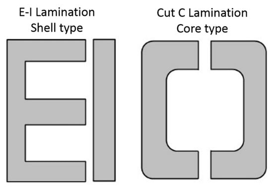
Figure 1.
Types of different core laminations.
2. Research Flow Diagram
In Figure 2, the first step of the research is shown, which is the selection of cores from different materials; in this study, two cores are selected for analysis (iron and silicon). Both of these cores are theoretically and practically tested, verified in the fabrication section, and losses are calculated. A transformer loss analysis is carried out on the basis of the output after the loss calculation of each core. A comperhensive analysis is conducted based on this result.
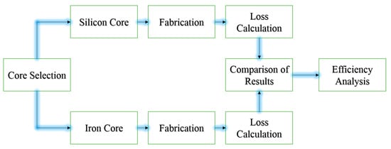
Figure 2.
Research flow diagram.
3. Methodology
A transformer is manufactured by considering many aspects. In the beginning, we assumed some design constants and set some design parameters. The theoretical design was established first. Then, we made a practical design and compared the two designs. Next, the design of the transformer is explained step by step. Theoretically, we set design parameters according to the type of material. We set the core dimensions, type of core, type of winding, size of winding, resistances and reactance.
3.1. Design of Core
The E-I core is normally used, and is shown in Figure 3. This core has three limbs and two yokes. The central limb has a double width because it has a double flux, as opposed to the other cores. We used a bobbin of 1.5 × 1.5 in2 for 500 VA transformers, and the width of central limb was 1.5 inch. The width of the side limb was 0.75 inch; the width of the window was equal to the width of the side limb; the width of yoke was also equal to the width of the side limb; and the height of window was three times the width of the window.
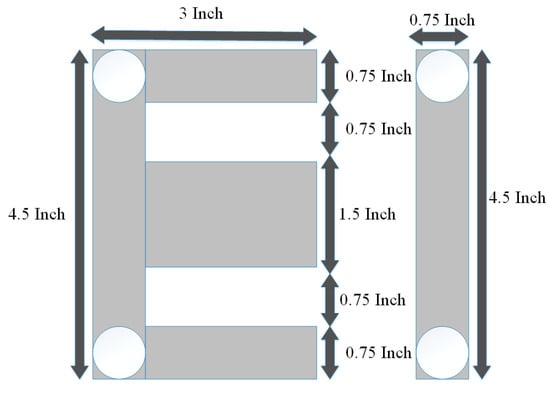
Figure 3.
EI Core Dimensions.
Winding Design
The coil was wound on the rectangular shape bobbin. There could be many layers of coil wound on the bobbin according to the number of turns. There was a different number of wires according to SWG (standard wire gauge) used in winding:
For Primary 23, no SWG was used because it could easily bear a 4.7 A current:
For Secondary 16, no SWG was used because it could bear a current of 22 A.
Table 1 given below describes the theoretical calculations of primary and secondary turns during the transformer designing.

Table 1.
Theoretical calculation of primary and secondary turns during core design.
4. Results and Discussion
Table 2 shows the different parameters related to the core analysis and requirements needed to design and manufacture the transformer core. In the table, the optimum efficiency is shown for both the theoretical and practical model, which reveals that the silicon-based cores have a relatively high core efficiency in both cases (theoretical and practical) as compared with the iron core. This demonstrates that there is room for improvement in the selection of core material, whereas Figure 4 shows the practical efficiency comparison between two different cores. Amorphous alloy-based cores with the addition of boron in the silicon core were recently proposed, because they have an efficient resistive nature against eddy current losses and improve the thermal stability and lifetime of T/F. Elements such as nickel and cobalt may be added to further increase the thermal stability, permeability, and T/F life span of these cores.
Table 2.
Core analysis under different parameters.
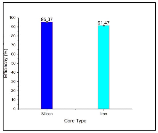
Figure 4.
Output Core Efficiency (%).
5. Conclusions
From the results, it is clear that the silicon core is much better than the iron core due to its special properties. The silicon core has lower core losses and a higher efficiency than the iron core. There is a low difference in cost, but a large difference in efficiency between the silicon core and iron core. Therefore, cost difference should be dismissed, and the silicon core should be used and preferred over the iron core. Moreover, the amorphous alloy core should be introduced to the local market in order to manufacture more efficient appliances and reduce the overall residential load.
Conflicts of Interest
The authors declare no conflict of interest.
References
- Dawood, K.; Komurgoz, G.; Isik, F. Modeling of Distribution Transformer for Analysis of Core Losses of Different Core Materials Using FEM. In Proceedings of the 2019 8th International Conference on Modeling Simulation and Applied Optimization (ICMSAO), Manama, Bahrain, 15–17 April 2019; pp. 1–5. [Google Scholar]
- Zhang, B.; Yan, N.; Du, J.; Han, F.; Wang, H. A Novel Approach to Investigate the Core Vibration in Power Transformers. IEEE Trans. Magn. 2018, 54, 1–4. [Google Scholar] [CrossRef]
- Dawood, K.; Cinar, M.A.; Alboyaci, B.; Sonmez, O. Modelling and Analysis of Transformer Using Numerical and Analytical Methods. In Proceedings of the 2017 18th International Symposium on Electromagnetic Fields in Mechatronics, Electrical and Electronic Engineering (ISEF) Book of Abstracts, Lodz, Poland, 14–16 September 2017. [Google Scholar]
- Bermúdez, A.; Gómez, D.; Salgado, P. Eddy-Current Losses in Laminated Cores and the Computation of an Equivalent Conductivity. IEEE Trans. Magn. 2008, 44, 4730–4738. [Google Scholar] [CrossRef]
- Bhatt, N.; Kaur, S.; Tayal, N. Transformer Loss Calculation and LV Winding Loss Reduction Using Finite Element Method. Anveshana’s Int. J. Res. Eng. Appl. Sci. 2016, 1, 34–38. [Google Scholar]
- Digalovski, M.; Petkovska, L.; Cvetkovski, G.; Lefley, P. Iron Loss Optimisation of a Distribution Transformer. IET Conf. Publ. 2014, 2014, 1–2. [Google Scholar]
- Roshen, W. Ferrite Core Loss for Power Magnetic Components Design. IEEE Trans. Magn. 1991, 27, 4407–4415. [Google Scholar] [CrossRef]
- Huo, C.; Wang, Y.; Wu, S.; Yang, Y.; Zhao, Z. Residual Flux Density Measurement Method for Transformer Core Considering Relative Differential Permeability. IEEE Trans. Magn. 2021, 57, 7–10. [Google Scholar] [CrossRef]
- Li, H.; Wang, L.; Li, J.; Zhang, J. An Improved Loss-Separation Method for Transformer Core Loss Calculation and Its Experimental Verification. IEEE Access 2020, 8, 204847–204854. [Google Scholar] [CrossRef]
Publisher’s Note: MDPI stays neutral with regard to jurisdictional claims in published maps and institutional affiliations. |
© 2021 by the authors. Licensee MDPI, Basel, Switzerland. This article is an open access article distributed under the terms and conditions of the Creative Commons Attribution (CC BY) license (https://creativecommons.org/licenses/by/4.0/).