
Determine the Optimum Efficiency of Transformer Cores Using Comparative Study Method †


Abstract
:1. Introduction
1.1. Transformer Core Selection and Assembly
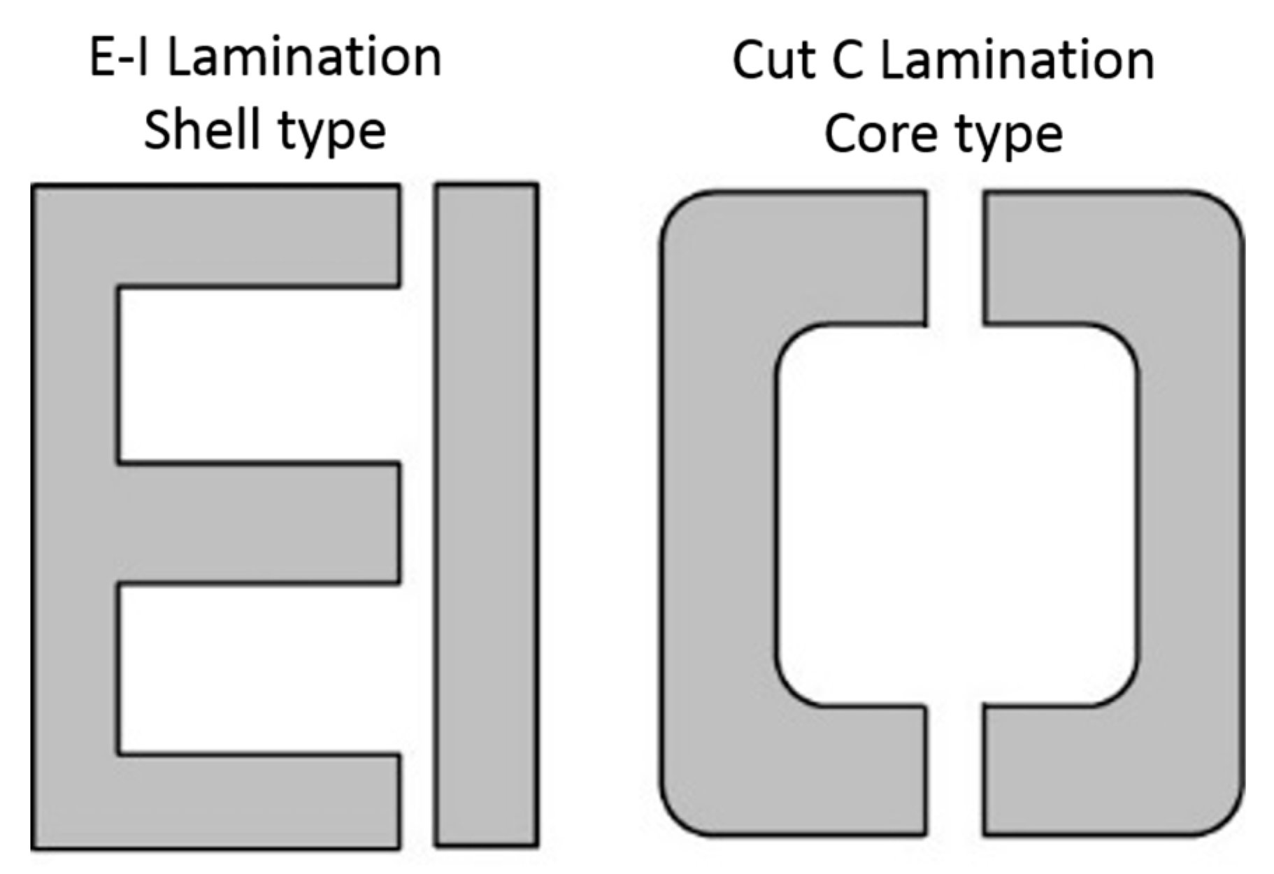
1.2. Types of Core Lamination
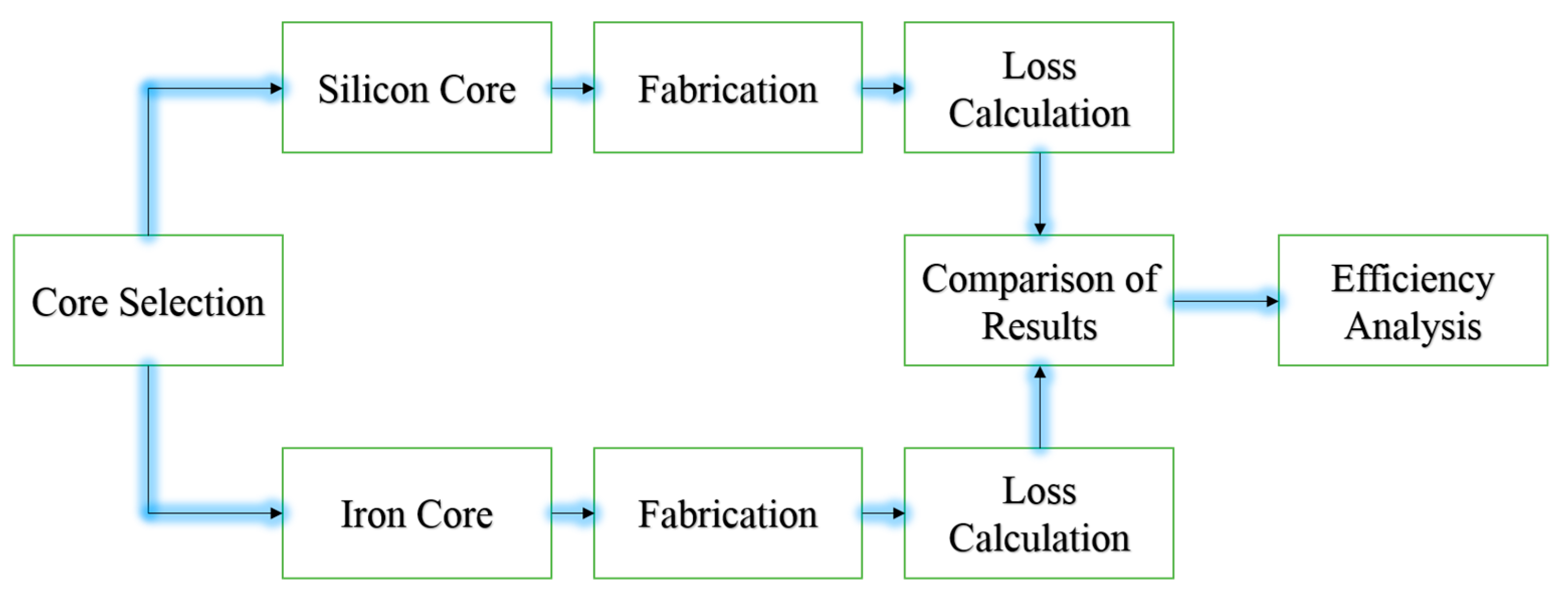
2. Research Flow Diagram
3. Methodology
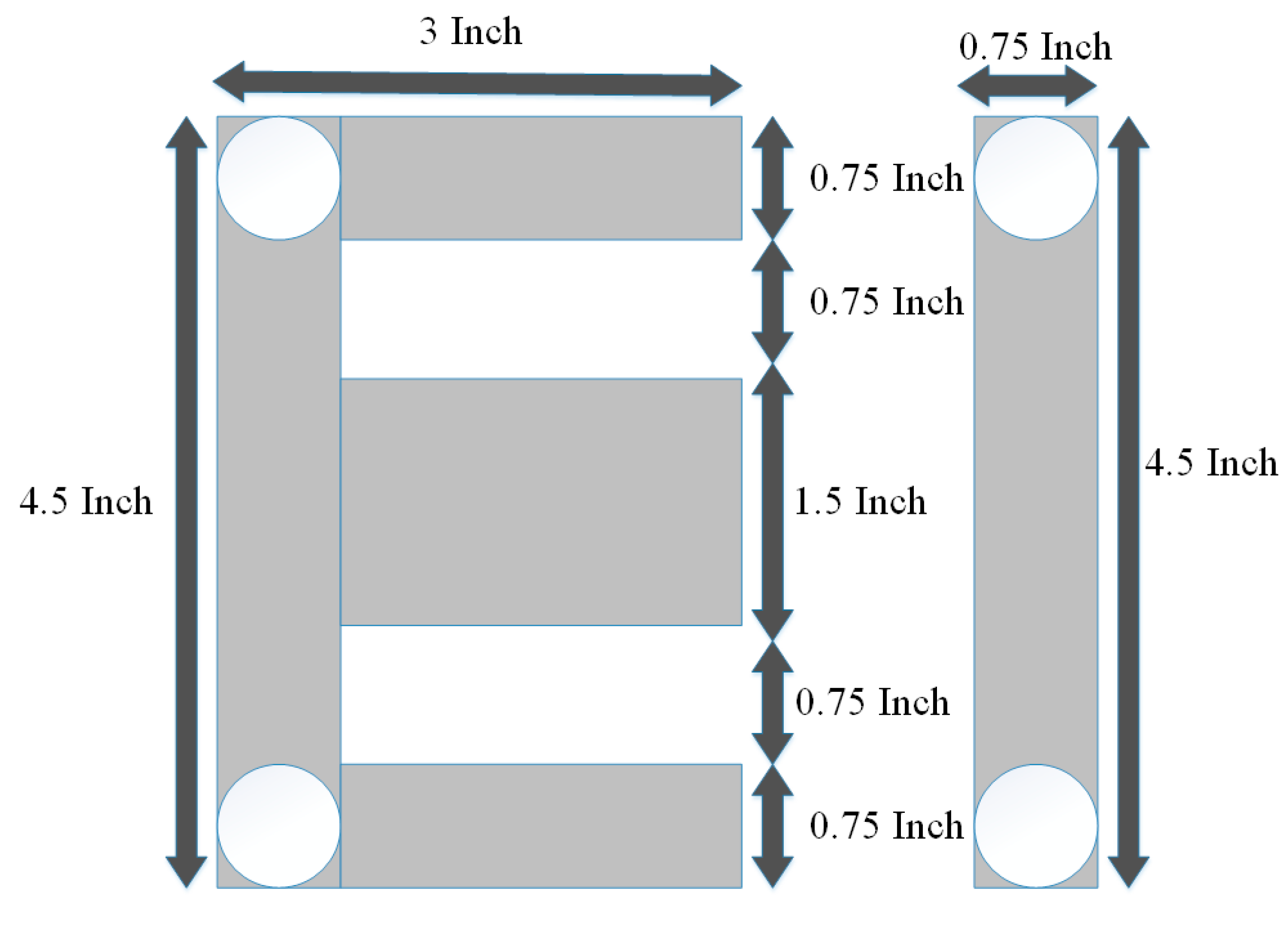
3.1. Design of Core
Winding Design
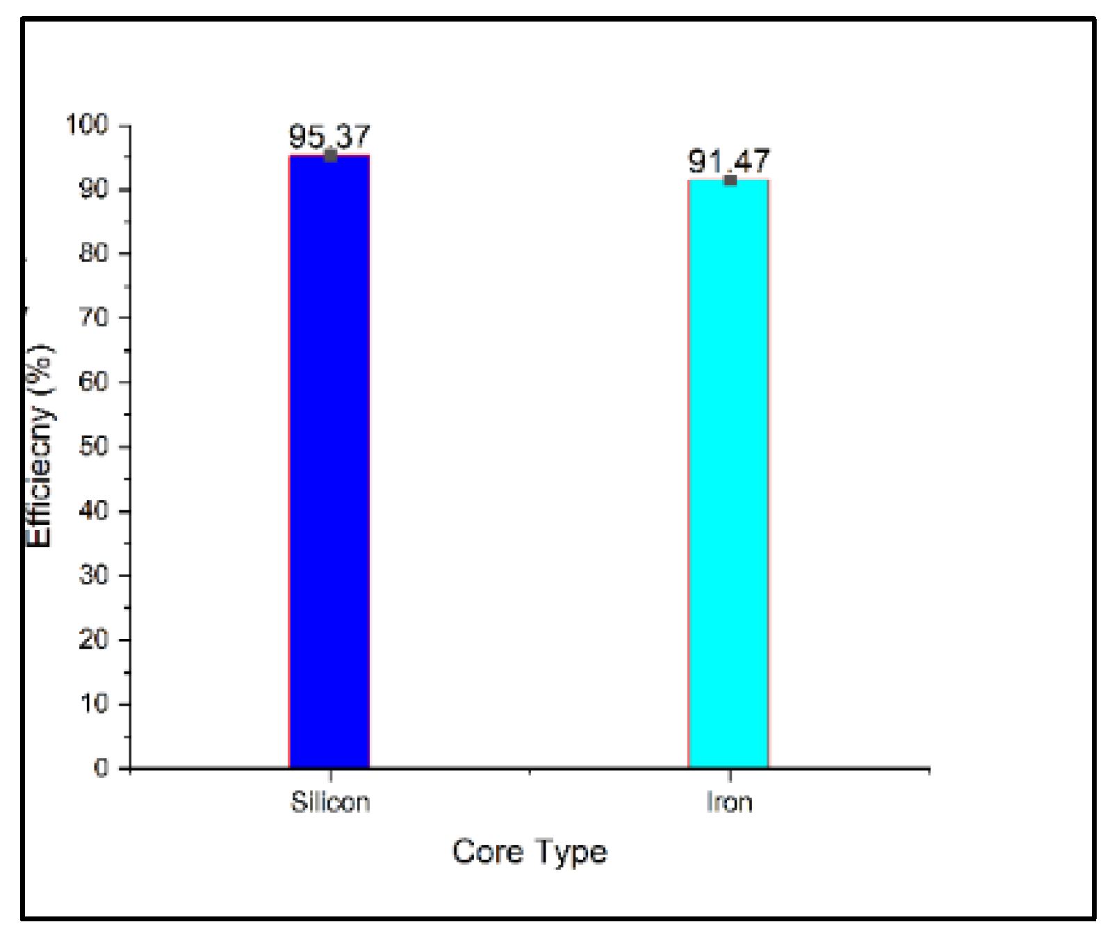
4. Results and Discussion
5. Conclusions
Conflicts of Interest
References
- Dawood, K.; Komurgoz, G.; Isik, F. Modeling of Distribution Transformer for Analysis of Core Losses of Different Core Materials Using FEM. In Proceedings of the 2019 8th International Conference on Modeling Simulation and Applied Optimization (ICMSAO), Manama, Bahrain, 15–17 April 2019; pp. 1–5. [Google Scholar]
- Zhang, B.; Yan, N.; Du, J.; Han, F.; Wang, H. A Novel Approach to Investigate the Core Vibration in Power Transformers. IEEE Trans. Magn. 2018, 54, 1–4. [Google Scholar] [CrossRef]
- Dawood, K.; Cinar, M.A.; Alboyaci, B.; Sonmez, O. Modelling and Analysis of Transformer Using Numerical and Analytical Methods. In Proceedings of the 2017 18th International Symposium on Electromagnetic Fields in Mechatronics, Electrical and Electronic Engineering (ISEF) Book of Abstracts, Lodz, Poland, 14–16 September 2017. [Google Scholar]
- Bermúdez, A.; Gómez, D.; Salgado, P. Eddy-Current Losses in Laminated Cores and the Computation of an Equivalent Conductivity. IEEE Trans. Magn. 2008, 44, 4730–4738. [Google Scholar] [CrossRef]
- Bhatt, N.; Kaur, S.; Tayal, N. Transformer Loss Calculation and LV Winding Loss Reduction Using Finite Element Method. Anveshana’s Int. J. Res. Eng. Appl. Sci. 2016, 1, 34–38. [Google Scholar]
- Digalovski, M.; Petkovska, L.; Cvetkovski, G.; Lefley, P. Iron Loss Optimisation of a Distribution Transformer. IET Conf. Publ. 2014, 2014, 1–2. [Google Scholar]
- Roshen, W. Ferrite Core Loss for Power Magnetic Components Design. IEEE Trans. Magn. 1991, 27, 4407–4415. [Google Scholar] [CrossRef]
- Huo, C.; Wang, Y.; Wu, S.; Yang, Y.; Zhao, Z. Residual Flux Density Measurement Method for Transformer Core Considering Relative Differential Permeability. IEEE Trans. Magn. 2021, 57, 7–10. [Google Scholar] [CrossRef]
- Li, H.; Wang, L.; Li, J.; Zhang, J. An Improved Loss-Separation Method for Transformer Core Loss Calculation and Its Experimental Verification. IEEE Access 2020, 8, 204847–204854. [Google Scholar] [CrossRef]


| Silicon Core | Iron Core |
|---|---|
| Ai = 2.25 inch2 = 0.001451 m2 | Ai = 2.25 inch2 = 0.001451 m2 |
| Bm = 1.3 wb/m2 | Bm = 1 wb/m2 |
| Te = 1/4.44 × f × B × A | Te = 1/4.44 × f × B × A |
| =1/4.44 × 50 × 1.3 × 0.001451 | =1/4.44 × 50 × 1 × 0.00145 |
| =2.38 turn/v | =3.104 turn/v |
| Primary turns = 2.38 × 220 = 525 | Primary turns = 3.104 × 220 = 683 |
| Secondary turns = 2.38 × 24 = 57 | Secondary turns = 3.104 × 24 = 74.5 |
| Corez Materials | Analysis Mode | Rc Ω | Xm Ω | Req Ω | Xeq Ω | Pcore W | Pcu W | % |
|---|---|---|---|---|---|---|---|---|
| Silicon | Theoretical | 3500 | 4600 | 50 | 15 | 13.81 | 5.73 | 95.62 |
| Practical | 3448.2 | 4551 | 51.35 | 17.9 | 14 | 6.62 | 95.37 | |
| Iron | Theoretical | 1700 | 2100 | 50 | 20 | 28.47 | 5.57 | 92.15 |
| Practical | 1587.3 | 1964 | 53.40 | 24.2 | 30.4 | 6.89 | 91.47 |
Publisher’s Note: MDPI stays neutral with regard to jurisdictional claims in published maps and institutional affiliations. |
© 2021 by the authors. Licensee MDPI, Basel, Switzerland. This article is an open access article distributed under the terms and conditions of the Creative Commons Attribution (CC BY) license (https://creativecommons.org/licenses/by/4.0/).
Share and Cite
Zahoor, N.; Dogar, A.A.; Hussain, A. Determine the Optimum Efficiency of Transformer Cores Using Comparative Study Method. Eng. Proc. 2021, 12, 35. https://doi.org/10.3390/engproc2021012035
Zahoor N, Dogar AA, Hussain A. Determine the Optimum Efficiency of Transformer Cores Using Comparative Study Method. Engineering Proceedings. 2021; 12(1):35. https://doi.org/10.3390/engproc2021012035
Chicago/Turabian StyleZahoor, Nabeel, Abid Ali Dogar, and Akhtar Hussain. 2021. "Determine the Optimum Efficiency of Transformer Cores Using Comparative Study Method" Engineering Proceedings 12, no. 1: 35. https://doi.org/10.3390/engproc2021012035
APA StyleZahoor, N., Dogar, A. A., & Hussain, A. (2021). Determine the Optimum Efficiency of Transformer Cores Using Comparative Study Method. Engineering Proceedings, 12(1), 35. https://doi.org/10.3390/engproc2021012035