

Feasibility Study for Monitoring an Ultrasonic System Using Structurally Integrated Piezoceramics


Abstract
1. Introduction
2. Materials and Methods
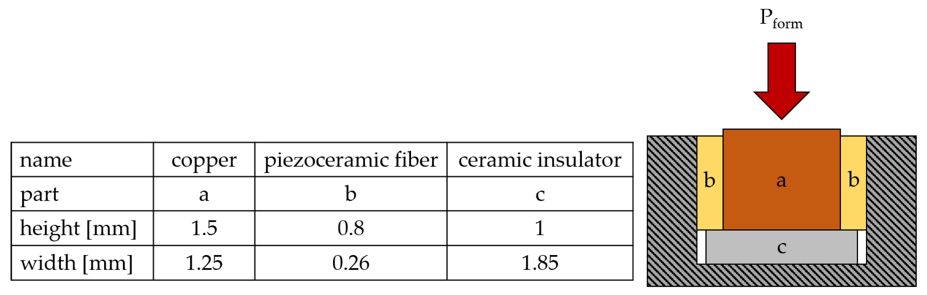
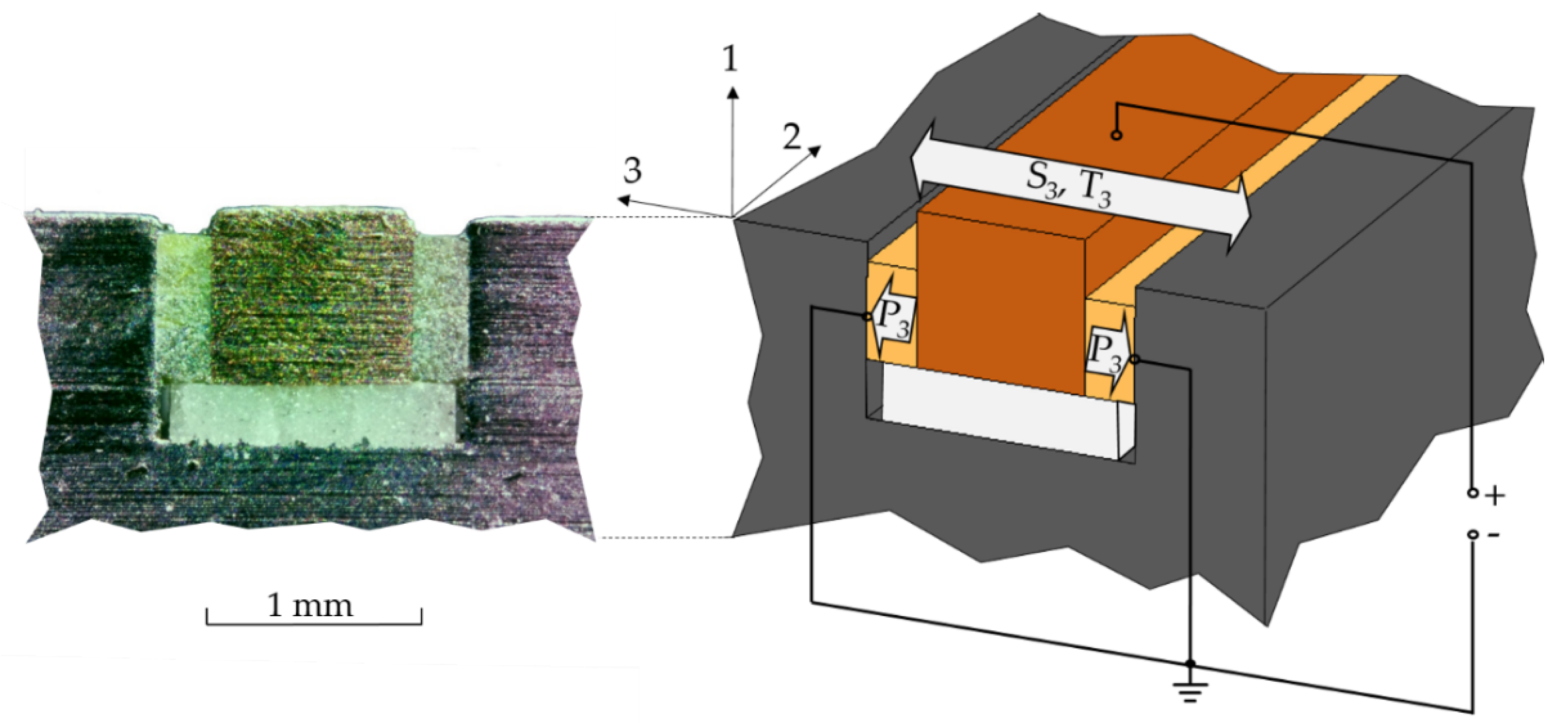
2.1. Structurally Integrated Piezoceramic
2.2. Ultrasonic System
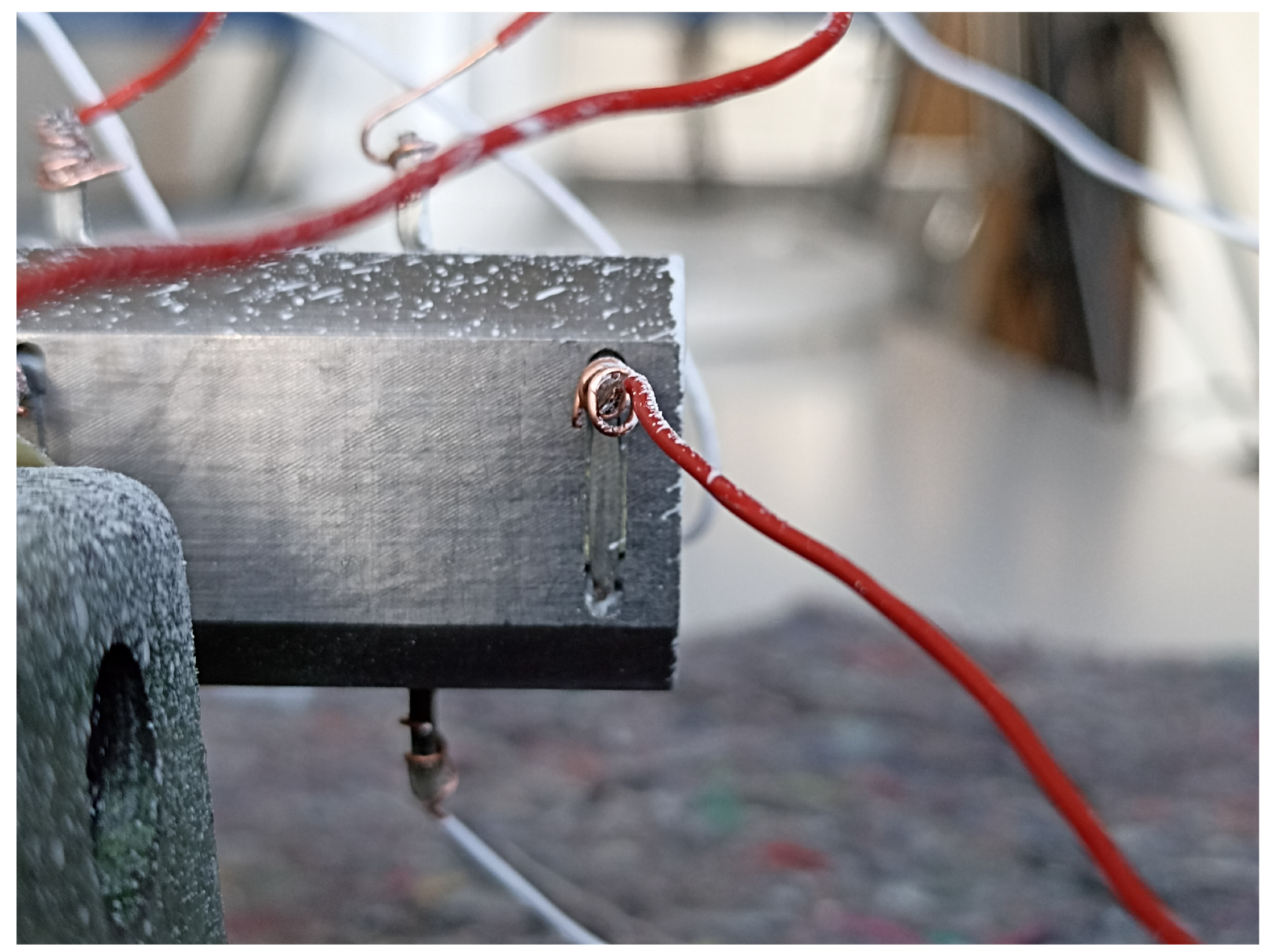
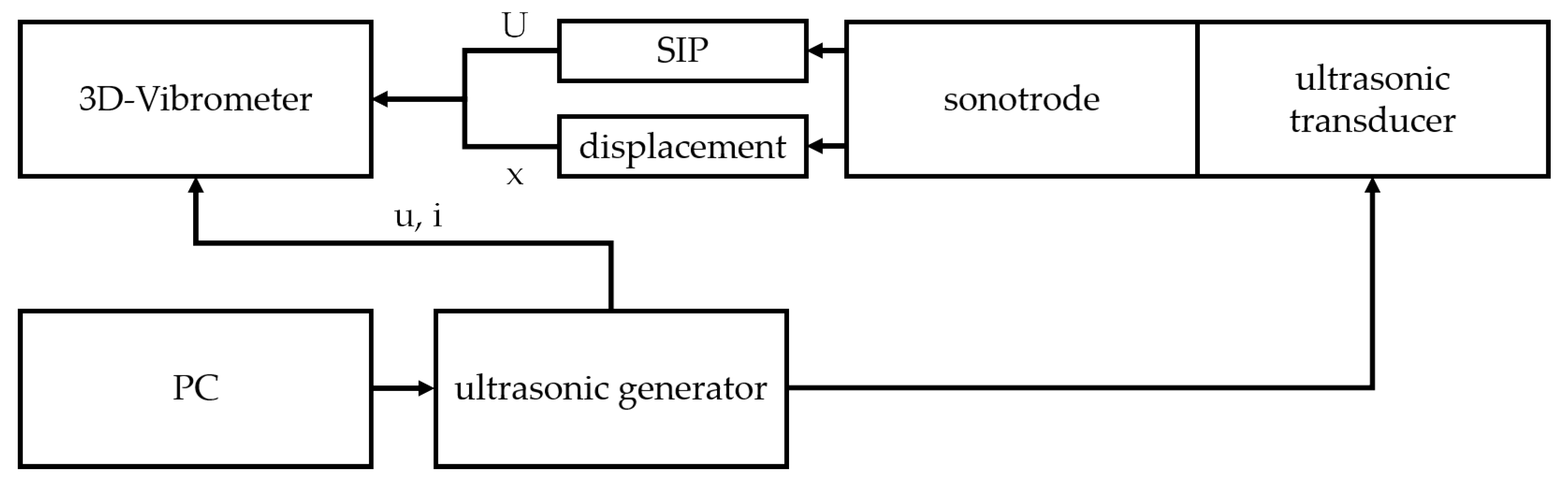
2.3. Experimental Setup
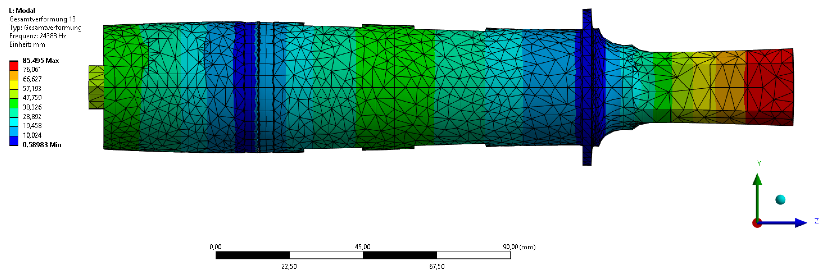
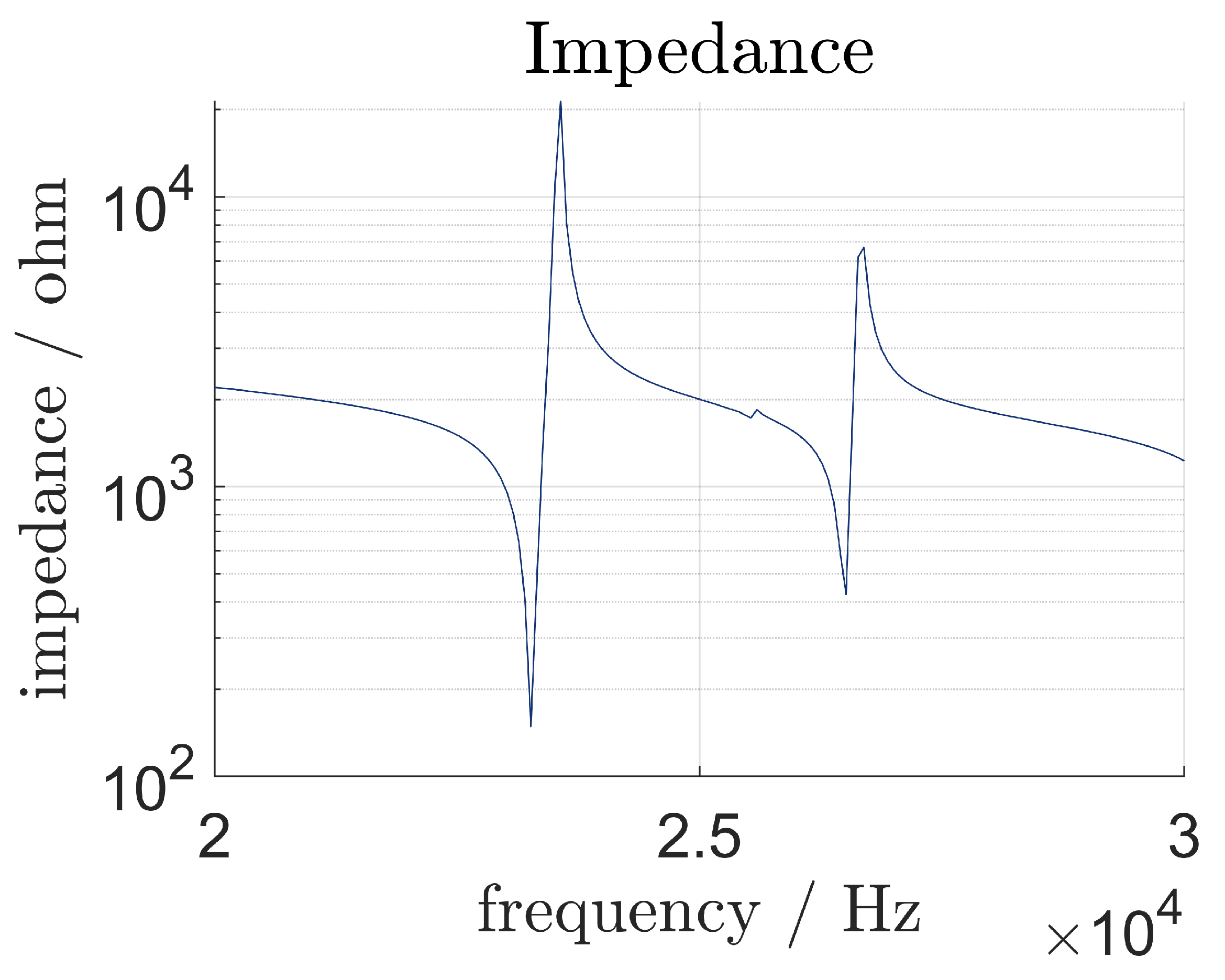
2.4. Preliminary Investigations
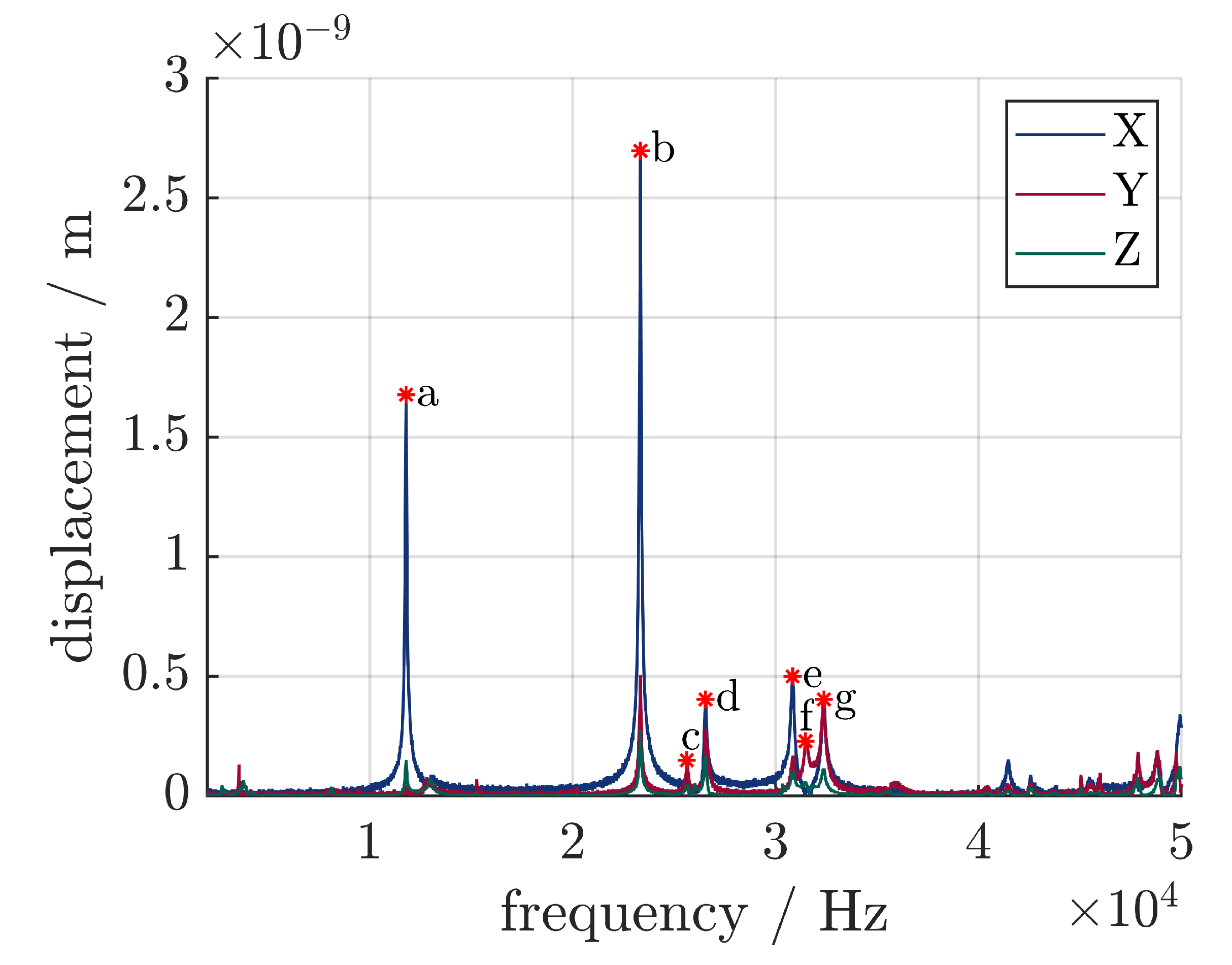
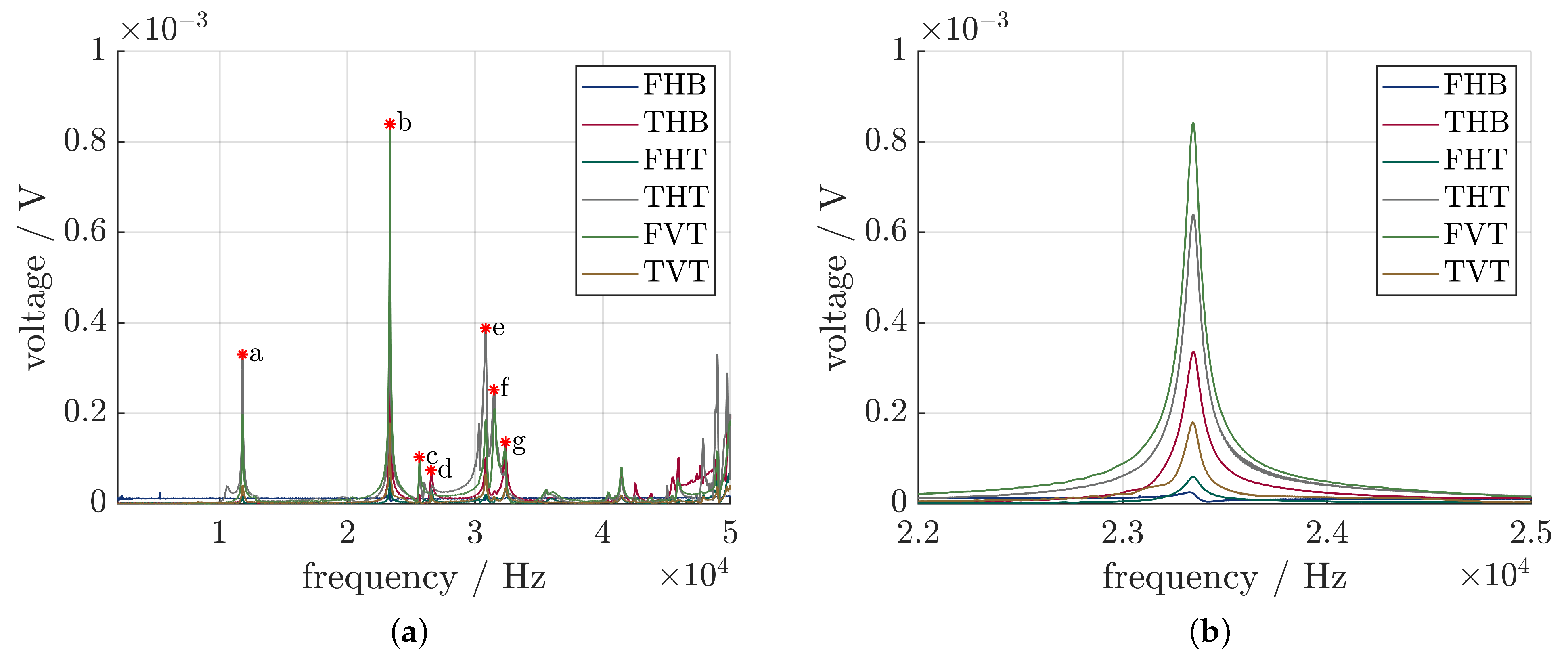
- 11,798 Hz: first longitudinal vibration mode (one node at the contact point between the transducer and sonotrode);
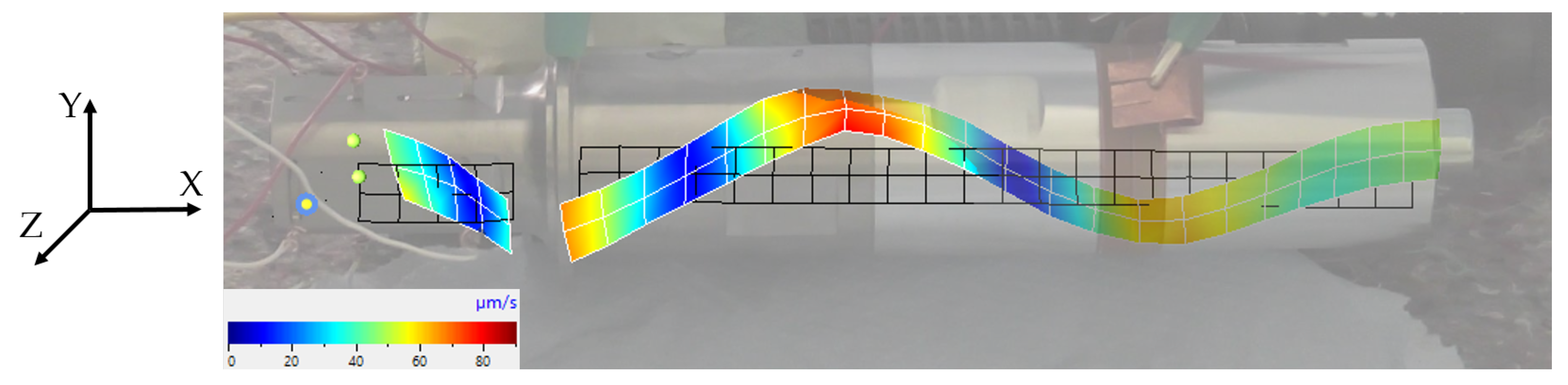
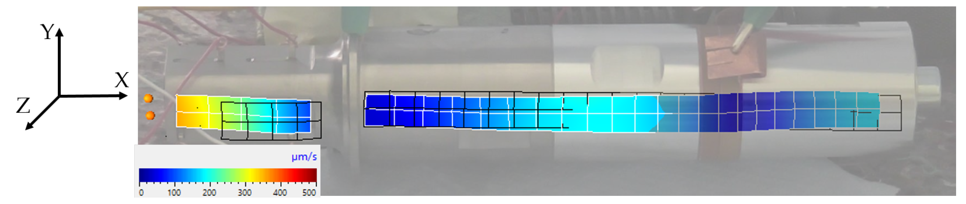
- 23,344 Hz: second longitudinal vibration mode (the desired resonance frequency); see Figure 7;
- 26,553 Hz: bending mode; see Figure 8;
- 30,859 Hz: combined bending and longitudinal mode;
- 32,373 Hz: bending mode.
3. Results
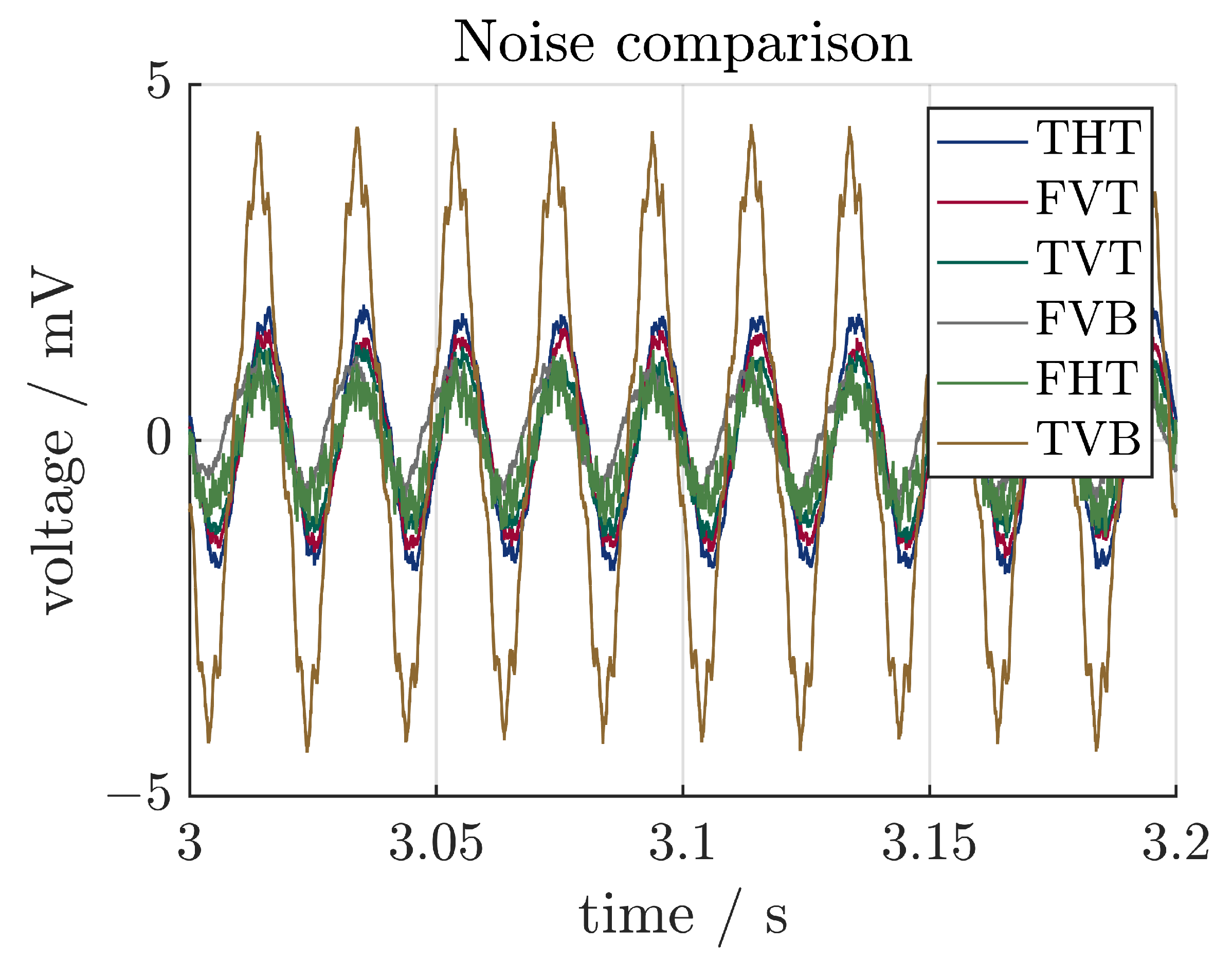
3.1. Noise
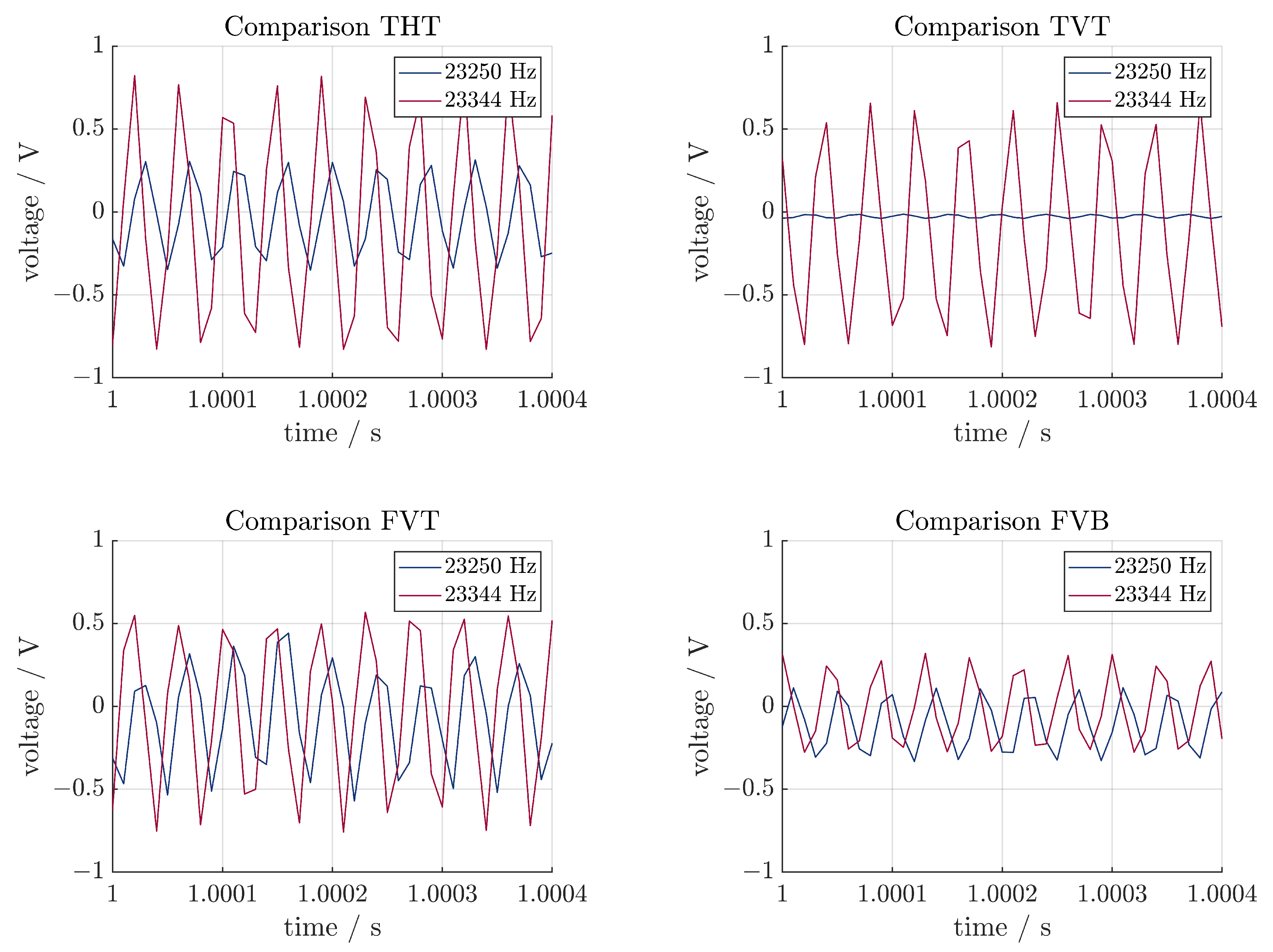
3.2. Comparison of the Sensors
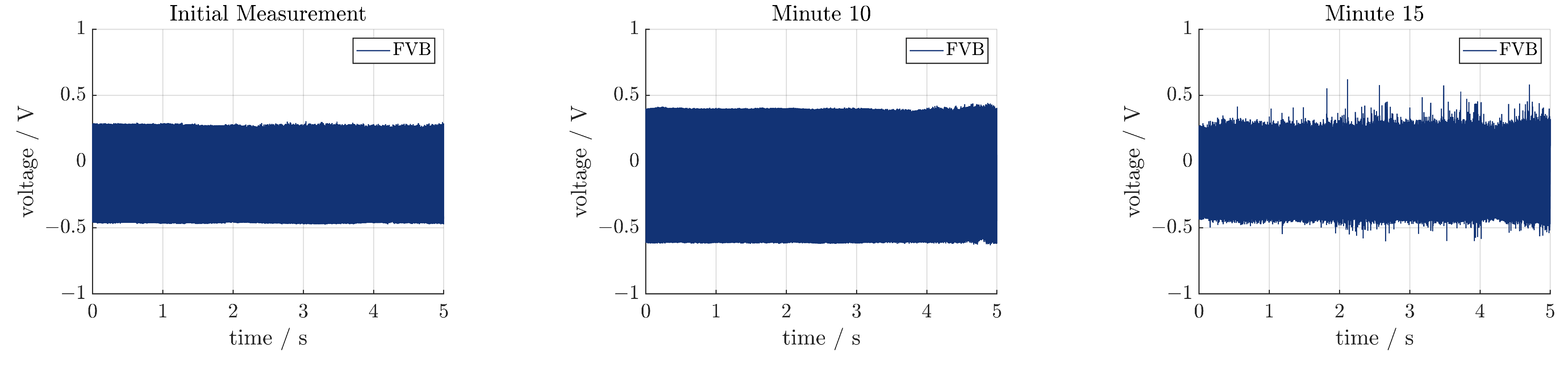
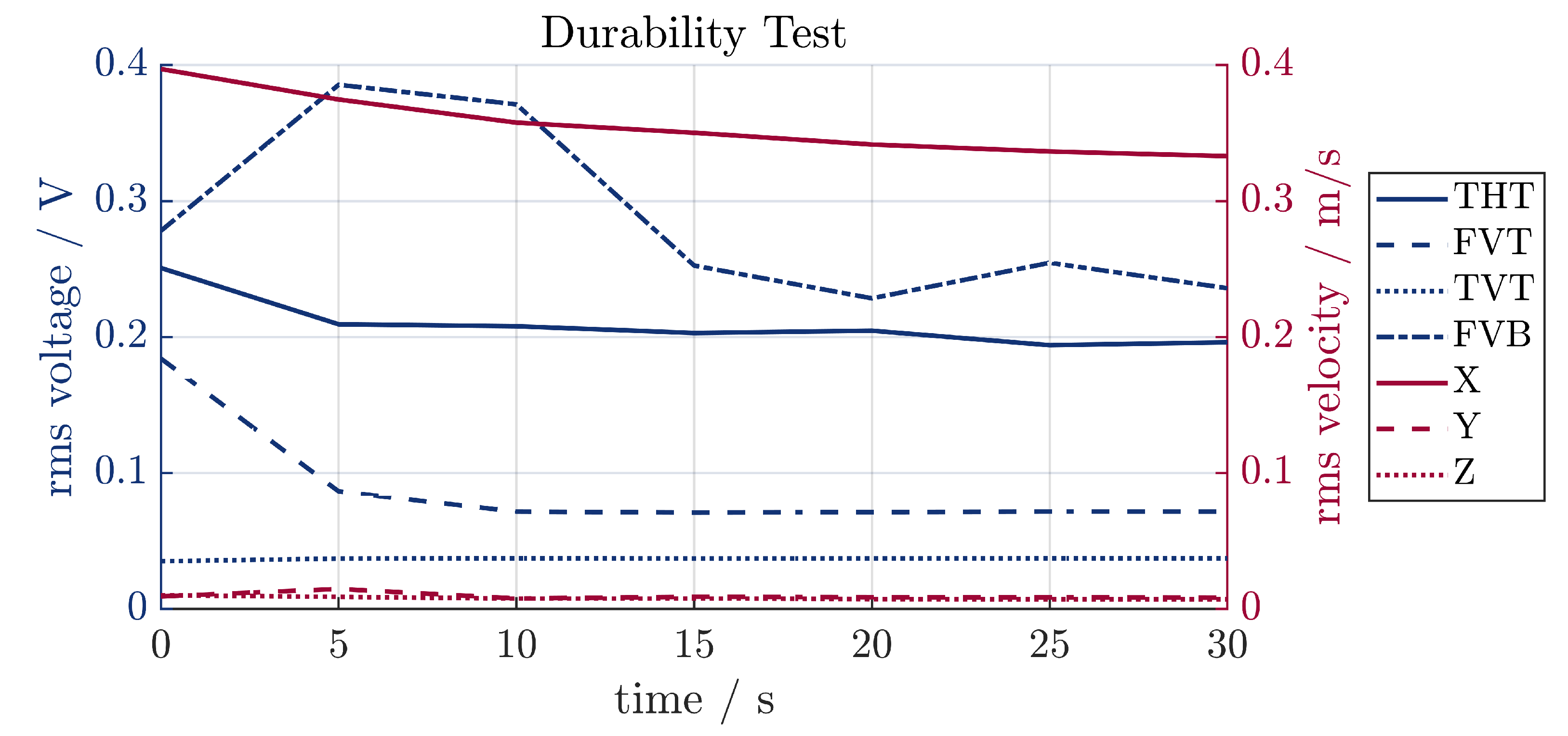
3.3. Durability Test
4. Discussion
Author Contributions
Funding
Institutional Review Board Statement
Informed Consent Statement
Data Availability Statement
Conflicts of Interest
References
- Neugebauer, R.; Denkena, B.; Wegener, K. Mechatronic Systems for Machine Tools. CIRP Ann. 2007, 56, 657–686. [Google Scholar] [CrossRef]
- Gallego-Juarez, J.A.; Graff, K.F.E. Power Ultrasonics: Applications of High-Intensity Ultrasound, 1st ed.; Woodhead Publishing: Amsterdam, The Netherlands, 2015; Volume 66. [Google Scholar]
- Kumar, S.; Wu, C.S.; Pahdy, G.K.; Ding, W. Application of ultrasonic vibrations in welding and metal processing: A status review. J. Manuf. Process. 2017, 26, 295–322. [Google Scholar] [CrossRef]
- Huang, Y.M.; Wu, Y.S.; Huang, J.Y. The influence of ultrasonic vibration-assisted micro-deep drawing process. Int. J. Adv. Manuf. Technol. 2014, 71, 1455–1461. [Google Scholar] [CrossRef]
- Brehl, D.E.; Dow, T.A. Review of vibration-assited machining. Precis. Eng. 2008, 32, 153–172. [Google Scholar] [CrossRef]
- Schubert, A.; Nestler, A.; Pinternagel, S.; Zeidler, H. Influence of ultrasonic vibration assistance on the surface integrity in turning of the aluminium alloy AA2017. Mater. Und Werkst. 2011, 42, 658–665. [Google Scholar] [CrossRef]
- Nestler, A.; Schubert, A. Surface Properties in Ultrasonic Vibration Assisted Turning of Particle Reinforced Aluminium Matrix Composites. Procedia CIRP 2014, 13, 125–130. [Google Scholar] [CrossRef]
- Zhang, R.; Steinert, P.; Schubert, A. Microstructuring of Surfaces by Two-stage Vibration-assisted Turning. Procedia CIRP 2014, 14, 136–141. [Google Scholar] [CrossRef]
- Arnold, F.; Mühlen, S. The resonance frequencies on mechanically pre-stressed ultrasonic piezotransducers. Ultrasonics 2001, 39, 1–5. [Google Scholar] [CrossRef]
- Yokozawa, H.; Twiefel, J.; Weinstein, M.; Morita, T. Dynamic resonant frequency control of ultrasonic transducer for stabilizing resonant state in wide frequency band. Jpn. J. Appl. Phys. 2017, 56, 07JE08. [Google Scholar] [CrossRef]
- Babitsky, V.I.; Astashev, V.K.; Kalashnikov, A.N. Autoresonant control of nonlinear mode in ultrasonic transducer for machining applications. Ultrasonics 2004, 42, 29–35. [Google Scholar] [CrossRef]
- Babitsky, V.I.; Kalashnikov, A.N.; Molodtsov, F.V. Autoresonant control of ultrasonically assisted cutting. Mechatronics 2004, 14, 91–114. [Google Scholar] [CrossRef]
- Dong, H.J.; Wu, J.; Zhang, G.Y.; Wu, H.F. An improved phase-locked loop method for automatic resonance frequency tracing based on static capacitance broadband compensation for a high-power ultrasonic transducer. IEEE Trans. Ultrason. Ferroelectr. Freq. Control 2012, 59, 205–210. [Google Scholar] [CrossRef]
- Xie, Y.; Zhou, Y. A Novel Method on PLL Control. Electron. Signal Process. 2011, 97, 335–342. [Google Scholar]
- Voronina, S.; Babitsky, V.; Meadows, A. Modelling of autoresonant control of ultrasonic transducer for machining applications. Proc. Inst. Mech. Eng. Part C J. Mech. Eng. Sci. 2008, 222, 1957–1974. [Google Scholar] [CrossRef]
- Li, X.; Meadows, A.; Babitsky, V.; Parkin, R. Experimental analysis on autoresonant control of ultrasonically assisted drilling. Mechatronics 2015, 29, 57–66. [Google Scholar] [CrossRef]
- Kimme, S.; Hafez, N.; Titsch, C.; Werner, J.M.; Nestler, A.; Drossel, W.G. Close-to-process strain measurement in ultrasonic and vibration-assisted turning. J. Sens. Sens. Syst. 2019, 8, 285–292. [Google Scholar] [CrossRef]
- Yu, F.; Zhang, C.; Gan, X.; Hu, X. Investigation on self-sensing monitoring and resonant control of ultrasonic vibration-assisted cutting. Int. J. Adv. Manuf. Technol. 2023, 125, 2435–2453. [Google Scholar] [CrossRef]
- Teti, R.; Mourtzis, D.; D’Addona, D.M.; Caggiano, A. Process monitoring of machining. CIRP Ann. 2022, 71, 529–552. [Google Scholar] [CrossRef]
- Eiras, J.N.; Gavérina, L.; Roche, J.M. Durability Assessment of Bonded Piezoelectric Wafer Active Sensors for Aircraft Health Monitoring Applications. Sensors 2024, 24, 450. [Google Scholar] [CrossRef] [PubMed]
- Khattak, M.M.; Headings, L.M.; Dapino, M.J. Dynamic Response of a Polyvinylidene Fluoride (PVDF) Sensor Embedded in a Metal Structure Using Ultrasonic Additive Manufacturing. Actuators 2023, 12, 428. [Google Scholar] [CrossRef]
- Modler, N.; Winkler, A.; Filippatos, A.; Weck, D.; Dannemann, M. Function-integrative Lightweight Engineering—Design Methods and Applications. Chem. Ing. Tech. 2020, 92, 949–959. [Google Scholar] [CrossRef]
- Werner, J.M.; Engelmann, M.; Schmidt, M.; Titsch, C.; Dix, M.; Drossel, W.G. Comparison of Structural Integrated Piezoceramics, Piezoelectric Patches and Strain Gauges for Condition Monitoring. Sensors 2022, 22, 8847. [Google Scholar] [CrossRef]
- Müller, M.; Müller, B.; Hensel, S.; Nestler, M.; Jahn, S.; Müller, R.; Schubert, A.; Drossel, W.G. Structural integration of PZT fibers in deep drawn sheet metal for material-integrated health monitoring. Mechatronics 2016, 34, 100. [Google Scholar] [CrossRef]
- Schubert, A.; Koriath, H.J.; Wittstock, V.; Müller, B.; Pierer, A.; Schmidt, M. Advanced Micro Structuring and Joining Technologies for Direct Integration of Piezo Fibers into Metallic Materials. Adv. Eng. Mater. 2018, 20, 1800472. [Google Scholar] [CrossRef]
- Moharana, S.; Bhalla, S. Influence of adhesive bond layer on power and energy transduction efficiency of piezo-impedance transducer. J. Intell. Mater. Syst. Struct. 2015, 26, 247–259. [Google Scholar] [CrossRef]
- Sheau, W.J.; Huang, R.T.; Wang, C.C. Influence of bonding glues on the vibration of piezoelectric fans. Sens. Actuators A Phys. 2008, 148, 115–121. [Google Scholar] [CrossRef]
- Yanaseko, T.; Sato, S.; Kuboki, I.; Mossi, K.; Anasuma, H. Vibration Viscosity Sensor for Engine Oil Monitoring Using Metal Matrix Piezoelectric Composite. Materials 2019, 12, 3415. [Google Scholar] [CrossRef]
- Ensminger, D.; Bond, L.J. Ultrasonics: Fundamentals, Technologies, and Applications, 3rd ed.; CRC Press: Boca Raton, FL, USA, 2011. [Google Scholar]
- Al-Budairi, H. A design approach for longitudinal–torsional ultrasonic transducers. Sens. Actuators A Phys. 2013, 198, 99–106. [Google Scholar] [CrossRef]
- Nad, M. Ultrasonic horn design for ultrasonic machining technologies. Appl. Comput. Mech. 2015, 4, 79–88. [Google Scholar]


| Designation | Position | Orientation | Top/Bottom |
|---|---|---|---|
| FHB | flange | horizontal | bottom |
| THB | tip | horizontal | bottom |
| FHT | flange | horizontal | top |
| THT | tip | horizontal | top |
| FVT | flange | vertical | top |
| TVT | tip | vertical | top |
| FVB | flange | vertical | bottom |
| TVB | tip | vertical | bottom |
| Parameter | Sonox P8 (Actor) | M1100 (Sensor) |
|---|---|---|
| [kg/] | 7700 | 8100 |
| [ ] | ||
| e [C/] | ||
| c [MPa] |
| Experiment | Excitation | Generator | Result |
|---|---|---|---|
| impedance analysis | frequency sweep | internal generator | electrical resonance frequency |
| vibration shape analysis | periodic chirp | internal generator | mechanical resonance frequencies and vibration shapes |
| analysis of the piezoelectric sensors | fixed frequency | external generator | signals for the piezoelectric sensors |
| endurance test | fixed frequency | external generator | quality of the assembly, signal quality of the piezoceramic sensors |
Disclaimer/Publisher’s Note: The statements, opinions and data contained in all publications are solely those of the individual author(s) and contributor(s) and not of MDPI and/or the editor(s). MDPI and/or the editor(s) disclaim responsibility for any injury to people or property resulting from any ideas, methods, instructions or products referred to in the content. |
© 2024 by the authors. Licensee MDPI, Basel, Switzerland. This article is an open access article distributed under the terms and conditions of the Creative Commons Attribution (CC BY) license (https://creativecommons.org/licenses/by/4.0/).
Share and Cite
Werner, J.M.; Krüger, T.; Drossel, W.-G. Feasibility Study for Monitoring an Ultrasonic System Using Structurally Integrated Piezoceramics. Sensors 2024, 24, 1036. https://doi.org/10.3390/s24031036
Werner JM, Krüger T, Drossel W-G. Feasibility Study for Monitoring an Ultrasonic System Using Structurally Integrated Piezoceramics. Sensors. 2024; 24(3):1036. https://doi.org/10.3390/s24031036
Chicago/Turabian StyleWerner, Jonas M., Tim Krüger, and Welf-Guntram Drossel. 2024. "Feasibility Study for Monitoring an Ultrasonic System Using Structurally Integrated Piezoceramics" Sensors 24, no. 3: 1036. https://doi.org/10.3390/s24031036
APA StyleWerner, J. M., Krüger, T., & Drossel, W.-G. (2024). Feasibility Study for Monitoring an Ultrasonic System Using Structurally Integrated Piezoceramics. Sensors, 24(3), 1036. https://doi.org/10.3390/s24031036