


A Review of Skin-Wearable Sensors for Non-Invasive Health Monitoring Applications


Abstract
1. Introduction
2. Systematic Review of Skin-Wearable Health Monitoring Strategies
3. Electrical Signals Related to Neural Activity
3.1. Neural Electrical Signal Monitoring Mechanism
3.2. Neural Electrical Signal for Skin-Wearable Devices
4. Thermoelectrical Signal Measurement
4.1. Thermoelectrical Signal Monitoring Mechanism
4.2. Thermoelectrical Signal for Skin-Wearable Devices
5. Photoelectrical Signal Measurement
5.1. Photoelectrical Signal Monitoring Mechanism
5.2. Photoelectric Signal for Skin-Wearable Devices
6. Mechanical Signal Measurement
6.1. Mechanical Signal Monitoring Mechanism
6.2. Mechanical Signal for Skin-Wearable Devices
6.3. Acoustic Signals Measurement
7. Electrochemical Signal Measurement
7.1. Electrochemical Signal Monitoring Mechanism

| Analyte | Concentration in Sweat [196] | Method | Substrate | Recognition Element | Refs | |
|---|---|---|---|---|---|---|
| Sodium | 10–100 mM | Potentiometry | Temporary tattoo | Sodium ionophore | [218] | |
| Adhesive Tape | Sodium ionophore | [219] | ||||
| PMMA | Sodium ionophore | [220] | ||||
| PET | Sodium ionophore | [200,221] | ||||
| Chloride | 10–100 mM | Polyester | Ag/AgCl | [201] | ||
| PET | Ag/AgCl | [200] | ||||
| Potassium | 1–18.5 mM | PET | Potassium ionophore | [221] | ||
| Calcium | 0.41–12.4 mM | PET | Calcium ionophore | [222] | ||
| Ammonia | 0.1–1 mM | Temporary tattoo | Nonactin ionophore | [223] | ||
| Heavy metal | Pb | <100 | Square-wave stripping voltammetry | PET | Bismuth, gold | [224] |
| Cd | <100 | PET | Bismuth | [224] | ||
| Hg | <100 | PET | Gold | [224] | ||
| Cu | 100–1000 | PET | Gold | [224] | ||
| Zn | 100–1560 | PET | Bismuth | [224] | ||
| Temporary tattoo | Bismuth | [225] | ||||
| pH | 3–8 (4–6.8) | Potentiometry | PET | Hydrogen ionophore | [222] | |
| Temporary tattoo | Poly(aniline) | [226] | ||||
| PMMA | Poly(aniline) | [220] | ||||
| Colorimetry | PMMA | Bromophenol green (BCG), bromophenol purple (BCP) | [227] | |||
| PDMS | bromophenol purple (BCP) | [228] | ||||
| Thermal properties | 36.5–37.5 °C | PET | Thermochromic liquid crystals | [229] | ||
| Lactate | 5–20 nM | Chronoamperometry | Temporary tattoo | Lactate oxidase | [230] | |
| Parylene | Lactate oxidase | [231] | ||||
| PMMA | Lactate oxidase | [220] | ||||
| PET | Lactate oxidase | [221] | ||||
| Glucose | 10–200 | PET | Glucose oxidase | [200,221] | ||
7.2. Electrochemical Signal for Skin-Wearable Devices
8. Future Challenges and Opportunities
Funding
Institutional Review Board Statement
Informed Consent Statement
Data Availability Statement
Conflicts of Interest
References
- Anbar, M.; Gratt, B.M.; Hong, D. Thermology and facial telethermography. Part I: History and technical review. Dentomaxillofacial Radiol. 1998, 27, 61–67. [Google Scholar] [CrossRef] [PubMed]
- Zhang, L.; Kumar, K.S.; He, H.; Cai, C.J.; He, X.; Gao, H.; Yue, S.; Li, C.; Seet, R.C.-S.; Ren, H. Fully organic compliant dry electrodes self-adhesive to skin for long-term motion-robust epidermal biopotential monitoring. Nat. Commun. 2020, 11, 4683. [Google Scholar] [CrossRef]
- Narayanamurthy, V.; Padmapriya, P.; Noorasafrin, A.; Pooja, B.; Hema, K.; Nithyakalyani, K.; Samsuri, F. Skin cancer detection using non-invasive techniques. RSC Adv. 2018, 8, 28095–28130. [Google Scholar] [CrossRef] [PubMed]
- Webb, R.C.; Bonifas, A.P.; Behnaz, A.; Zhang, Y.; Yu, K.J.; Cheng, H.; Shi, M.; Bian, Z.; Liu, Z.; Kim, Y.-S.; et al. Ultrathin conformal devices for precise and continuous thermal characterization of human skin. Nat. Mater. 2013, 12, 938. [Google Scholar] [CrossRef] [PubMed]
- Stauffer, F.; Thielen, M.; Sauter, C.; Chardonnens, S.; Bachmann, S.; Tybrandt, K.; Peters, C.; Hierold, C.; Vörös, J. Skin Conformal Polymer Electrodes for Clinical ECG and EEG Recordings. Adv. Heal. Mater. 2018, 7, e1700994. [Google Scholar] [CrossRef]
- JLee, J.-W.; Yun, K.-S. ECG Monitoring Garment Using Conductive Carbon Paste for Reduced Motion Artifacts. Polymers 2017, 9, 439. [Google Scholar] [CrossRef]
- Biondi, A.; Santoro, V.; Viana, P.F.; Laiou, P.; Pal, D.K.; Bruno, E.; Richardson, M.P. Noninvasive mobile EEG as a tool for seizure monitoring and management: A systematic review. Epilepsia 2022, 63, 1041–1063. [Google Scholar] [CrossRef]
- Liu, Y.; Pharr, M.; Salvatore, G.A. Lab-on-Skin: A Review of Flexible and Stretchable Electronics for Wearable Health Monitoring. ACS Nano 2017, 11, 9614–9635. [Google Scholar] [CrossRef]
- Tierney, M.J.; Tamada, J.A.; Potts, R.O.; Jovanovic, L.; Garg, S. Clinical evaluation of the GlucoWatch® biographer: A continual, non-invasive glucose monitor for patients with diabetes. Biosens. Bioelectron. 2001, 16, 621–629. [Google Scholar] [CrossRef]
- Hussain, A.M.; Hussain, M.M. CMOS-Technology-Enabled Flexible and Stretchable Electronics for Internet of Everything Applications. Adv. Mater. 2016, 28, 4219–4249. [Google Scholar] [CrossRef]
- Khan, Y.; Ostfeld, A.E.; Lochner, C.M.; Pierre, A.; Arias, A.C. Monitoring of Vital Signs with Flexible and Wearable Medical Devices. Adv. Mater. 2016, 28, 4373–4395. [Google Scholar] [CrossRef]
- Trung, T.Q.; Lee, N.-E. Flexible and Stretchable Physical Sensor Integrated Platforms for Wearable Human-Activity Monitoringand Personal Healthcare. Adv. Mater. 2016, 28, 4338–4372. [Google Scholar] [CrossRef]
- Honghui, J. Motion-Aircraft Resistant Design of Photoplethysmograph Ring Sensor for Driver Monitoring. Doctoral Dissertation, Massachusetts Institute of Technology, Cambridge, MA, USA, 2004. [Google Scholar]
- Whitton, J.T.; Everall, J.D. The thickness of the epidermis. Br. J. Dermatol. 1973, 89, 467–476. [Google Scholar] [CrossRef]
- Arumugam, V.; Naresh, M.D.; Sanjeevi, R. Effect of strain rate on the fracture behaviour of skin. J. Biosci. 1994, 19, 307–313. [Google Scholar] [CrossRef]
- Flint, M. The biological basis of Langer’s lines. In The Ultrastructure of Collagen; Charles Thomas Springfield: Springfield, IL, USA, 1976; pp. 132–140. [Google Scholar]
- Gallagher, A.J.; Annaidh, A.N.; Bruyère, K. Dynamic Tensile Properties of Human Skin; International Research Council on the Biomechanics of Injury: Dublin, Ireland, 2012. [Google Scholar]
- Pawlaczyk, M.; Lelonkiewicz, M.; Wieczorowski, M. Age-dependent biomechanical properties of the skin. Adv. Dermatol. Allergol. Postȩpy Dermatol. I Alergol. 2013, 30, 302. [Google Scholar] [CrossRef] [PubMed]
- Joodaki, H.; Panzer, M.B. Skin mechanical properties and modeling: A review. Proc. Inst. Mech. Eng. Part H J. Eng. Med. 2018, 232, 323–343. [Google Scholar] [CrossRef]
- Bader, D.L.; Bowker, P. Mechanical characteristics of skin and underlying tissues in vivo. Biomaterials 1983, 4, 305–308. [Google Scholar] [CrossRef]
- Sanders, R. Torsional elasticity of human skin in vivo. Pflügers Arch. 1973, 342, 255–260. [Google Scholar] [CrossRef]
- Escoffier, C.; de Rigal, J.; Rochefort, A.; Vasselet, R.; Lévéque, J.-L.; Agache, P.G. Age-related mechanical properties of human skin: An in vivo study. J. Investig. Dermatol. 1989, 93, 53–357. [Google Scholar] [CrossRef]
- Manschot, J.F.M.; Brakkee, A.J.M. The measurement and modelling of the mechanical properties of human skin in vivo—I. The measurement. J. Biomech. 1986, 19, 511–515. [Google Scholar] [CrossRef] [PubMed]
- Grahame, R.; Holt, P.J.L. The Influence of Ageing on the in vivo Elasticity of Human Skin. Gerontology 1969, 15, 121–139. [Google Scholar] [CrossRef] [PubMed]
- García de Arquer, F.P.; Armin, A.; Meredith, P.; Sargent, E.H. Solution-processed semiconductors for next-generation photodetectors. Nat. Rev. Mater. 2017, 2, 16100. [Google Scholar] [CrossRef]
- Li, H.; Mao, P.; Davis, M.; Yu, Z. PEDOT:PSS-polyethylene oxide composites for stretchable and 3D-Printed thermoelectric devices. Compos. Commun. 2021, 23, 100599. [Google Scholar] [CrossRef]
- Bielecka, U.; Lutsyk, P.; Janus, K.; Sworakowski, J.; Bartkowiak, W. Effect of solution aging on morphology and electrical characteristics of regioregular P3HT FETs fabricated by spin coating and spray coating. Org. Electron. 2011, 12, 1768–1776. [Google Scholar] [CrossRef]
- Wu, H.; Kong, D.; Ruan, Z.; Hsu, P.-C.; Wang, S.; Yu, Z.; Carney, T.J.; Hu, L.; Fan, S.; Cui, Y. A transparent electrode based on a metal nanotrough network. Nat. Nanotechnol. 2013, 8, 421. [Google Scholar] [CrossRef]
- Sekitani, T.; Nakajima, H.; Maeda, H.; Fukushima, T.; Aida, T.; Hata, K.; Someya, T. Stretchable active-matrix organic light-emitting diode display using printable elastic conductors. Nat. Mater. 2009, 8, 494–499. [Google Scholar] [CrossRef]
- Kim, T.; Park, J.; Sohn, J.; Cho, D.; Jeon, S. Bioinspired, Highly Stretchable, and Conductive Dry Adhesives Based on 1D–2D Hybrid Carbon Nanocomposites for All-in-One ECG Electrodes. ACS Nano 2016, 10, 4770–4778. [Google Scholar] [CrossRef]
- Fan, J.A.; Yeo, W.-H.; Su, Y.; Hattori, Y.; Lee, W.; Jung, S.-Y.; Zhang, Y.; Liu, Z.; Cheng, H.; Falgout, L.; et al. Fractal design concepts for stretchable electronics. Nat. Commun. 2014, 5, 3266. [Google Scholar] [CrossRef]
- Wang, C.; Chen, X.; Wang, L.; Makihata, M.; Liu, H.-C.; Zhou, T.; Zhao, X. Bioadhesive ultrasound for long-term continuous imaging of diverse organs. Science 2022, 377, 517–523. [Google Scholar] [CrossRef]
- Lipomi, D.J.; Tee, B.C.-K.; Vosgueritchian, M.; Bao, Z. Stretchable Organic Solar Cells. Adv. Mater. 2011, 23, 1771–1775. [Google Scholar] [CrossRef]
- Kaltenbrunner, M.; White, M.S.; Głowacki, E.D.; Sekitani, T.; Someya, T.; Sariciftci, N.S.; Bauer, S. Ultrathin and lightweight organic solar cells with high flexibility. Nat. Commun. 2012, 3, 770. [Google Scholar] [CrossRef] [PubMed]
- Holloway, P.H. Gold/chromium metallizations for electronic devices. Gold Bull. 1979, 12, 99–106. [Google Scholar] [CrossRef]
- Kim, D.-H.; Lu, N.; Ma, R.; Kim, Y.-S.; Kim, R.-H.; Wang, S.; Wu, J.; Won, S.M.; Tao, H.; Islam, A.; et al. Epidermal Electronics. Science 2011, 333, 838–843. [Google Scholar] [CrossRef] [PubMed]
- Xu, B.; Akhtar, A.; Liu, Y.; Chen, H.; Yeo, W.-H.; Park, S.I.; Boyce, B.; Kim, H.; Yu, J.; Lai, H.-Y.; et al. An Epidermal Stimulation and Sensing Platform for Sensorimotor Prosthetic Control, Management of Lower Back Exertion, and Electrical Muscle Activation. Adv. Mater. 2016, 28, 4462–4471. [Google Scholar] [CrossRef]
- Jiang, H.; Khang, D.-Y.; Song, J.; Sun, Y.; Huang, Y.; Rogers, J.A. Finite deformation mechanics in buckled thin films on compliant supports. Proc. Natl. Acad. Sci. USA 2007, 104, 15607–15612. [Google Scholar] [CrossRef]
- Song, J.; Jiang, H.; Liu, Z.J.; Khang, D.Y.; Huang, Y.; Rogers, J.A.; Lu, C.; Koh, C.G. Buckling of a stiff thin film on a compliant substrate in large deformation. Int. J. Solids Struct. 2008, 45, 3107–3121. [Google Scholar] [CrossRef]
- Wolfe, S.; Cage, G.; Epstein, M.; Tice, L.; Miller, H.; Gordon, R. Metabolic studies of isolated human eccrine sweat glands. J. Clin. Investig. 1970, 49, 1880–1884. [Google Scholar] [CrossRef]
- Martínez-Corral, I.; Olmeda, D.; Diéguez-Hurtado, R.; Tammela, T.; Alitalo, K.; Ortega, S. In vivo imaging of lymphatic vessels in development, wound healing, inflammation, and tumor metastasis. Proc. Natl. Acad. Sci. USA 2012, 109, 6223–6228. [Google Scholar] [CrossRef]
- Lee, S.-J.; Park, C.; Lee, J.Y.; Kim, S.; Kwon, P.J.; Kim, W.; Jeon, Y.H.; Lee, E.; Yoon, Y.-S. Generation of pure lymphatic endothelial cells from human pluripotent stem cells and their therapeutic effects on wound repair. Sci. Rep. 2015, 5, 11019. [Google Scholar] [CrossRef]
- Baura, G.D. Preface. In Medical Device Technologies; Baura, G.D., Ed.; Academic Press: Oxford, UK, 2012; pp. ix–xi. [Google Scholar] [CrossRef]
- Council, N.R. Expanding the Vision of Sensor Materials; National Academies Press: Cambridge, MA, USA, 1995. [Google Scholar]
- Göpel, W.; Grandke, T.; Hesse, J.; Ko, W.H.; Zemel, J.N. Sensors: Fundamentals and General Aspects; VCH Publishers: Weinheim, Germany, 1989; Volume 1. [Google Scholar]
- Yamamoto, Y.; Yamamoto, D.; Takada, M.; Naito, H.; Arie, T.; Akita, S.; Takei, K. Efficient Skin Temperature Sensor and Stable Gel-Less Sticky ECG Sensor for a Wearable Flexible Healthcare Patch. Adv. Healthc. Mater. 2017, 6, 1700495. [Google Scholar] [CrossRef]
- Bae, W.G.; Kim, D.; Kwak, M.K.; Ha, L.; Kang, S.M.; Suh, K.Y. Enhanced Skin Adhesive Patch with Modulus-Tunable Composite Micropillars. Adv. Healthc. Mater. 2013, 2, 109–113. [Google Scholar] [CrossRef] [PubMed]
- Norton, J.J.S.; Lee, D.S.; Lee, J.W.; Lee, W.; Kwon, O.; Won, P.; Jung, S.-Y.; Cheng, H.; Jeong, J.-W.; Akce, A.; et al. Soft, curved electrode systems capable of integration on the auricle as a persistent brain–computer interface. Proc. Natl. Acad. Sci. USA 2015, 112, 3920–3925. [Google Scholar] [CrossRef]
- Lee, S.M.; Byeon, H.J.; Lee, J.H.; Baek, D.H.; Lee, K.H.; Hong, J.S.; Lee, S.-H. Self-adhesive epidermal carbon nanotube electronics for tether-free long-term continuous recording of biosignals. Sci. Rep. 2014, 4, 6074. [Google Scholar] [CrossRef] [PubMed]
- Tian, L.; Zimmerman, B.; Akhtar, A.; Yu, K.J.; Moore, M.; Wu, J.; Larsen, R.J.; Lee, J.W.; Li, J.; Liu, Y.; et al. Large-area MRI-compatible epidermal electronic interfaces for prosthetic control and cognitive monitoring. Nat. Biomed. Eng. 2019, 3, 194–205. [Google Scholar] [CrossRef] [PubMed]
- Jang, K.-I.; Jung, H.N.; Lee, J.W.; Xu, S.; Liu, Y.H.; Ma, Y.; Jeong, J.-W.; Song, Y.M.; Kim, J.; Kim, B.H.; et al. Ferromagnetic, Folded Electrode Composite as a Soft Interface to the Skin for Long-Term Electrophysiological Recording. Adv. Funct. Mater. 2016, 26, 7281–7290. [Google Scholar] [CrossRef] [PubMed]
- Hattori, Y.; Falgout, L.; Lee, W.; Jung, S.-Y.; Poon, E.; Lee, J.W.; Na, I.; Geisler, A.; Sadhwani, D.; Zhang, Y.; et al. Multifunctional Skin-Like Electronics for Quantitative, Clinical Monitoring of Cutaneous Wound Healing. Adv. Healthc. Mater. 2014, 3, 1597–1607. [Google Scholar] [CrossRef] [PubMed]
- Madhvapathy, S.; Ma, Y.; Patel, M.; Krishnan, S.; Wei, C.; Li, Y.; Xu, S.; Feng, X.; Huang, Y.-S.; Rogers, J. Epidermal Electronic Systems for Measuring the Thermal Properties of Human Skin at Depths of up to Several Millimeters. Adv. Funct. Mater. 2018, 28, 1802083. [Google Scholar] [CrossRef]
- Shin, J.; Jeong, B.; Kim, J.; Nam, V.B.; Yoon, Y.; Jung, J.; Hong, S.; Lee, H.; Eom, H.; Yeo, J. Sensitive wearable temperature sensor with seamless monolithic integration. Adv. Mater. 2020, 32, 1905527. [Google Scholar] [CrossRef]
- Yu, Y.; Peng, S.; Blanloeuil, P.; Wu, S.; Wang, C.H. Wearable Temperature Sensors with Enhanced Sensitivity by Engineering Microcrack Morphology in PEDOT:PSS–PDMS Sensors. ACS Appl. Mater. Interfaces 2020, 12, 36578–36588. [Google Scholar] [CrossRef]
- Webb, R.C.; Ma, Y.; Krishnan, S.; Li, Y.; Yoon, S.; Guo, X.; Feng, X.; Shi, Y.; Seidel, M.; Cho, N.H.; et al. Epidermal devices for noninvasive, precise, and continuous mapping of macrovascular and microvascular blood flow. Sci. Adv. 2015, 1, e1500701. [Google Scholar] [CrossRef]
- Webb, R.C.; Pielak, R.M.; Bastien, P.; Ayers, J.; Niittynen, J.; Kurniawan, J.; Manco, M.; Lin, A.; Cho, N.H.; Malyrchuk, V.; et al. Thermal transport characteristics of human skin measured in vivo using ultrathin conformal arrays of thermal sensors and actuators. PLoS ONE 2015, 10, e0118131. [Google Scholar] [CrossRef] [PubMed]
- Lochner, C.M.; Khan, Y.; Pierre, A.; Arias, A.C. All-organic optoelectronic sensor for pulse oximetry. Nat. Commun. 2014, 5, 5745. [Google Scholar] [CrossRef] [PubMed]
- Yokota, T.; Zalar, P.; Kaltenbrunner, M.; Jinno, H.; Matsuhisa, N.; Kitanosako, H.; Tachibana, Y.; Yukita, W.; Koizumi, M.; Someya, T. Ultraflexible organic photonic skin. Sci. Adv. 2016, 2, e1501856. [Google Scholar] [CrossRef] [PubMed]
- Choong, C.-L.; Shim, M.-B.; Lee, B.-S.; Jeon, S.; Ko, D.-S.; Kang, T.-H.; Bae, J.; Lee, S.H.; Byun, K.-E.; Im, J.; et al. Highly Stretchable Resistive Pressure Sensors Using a Conductive Elastomeric Composite on a Micropyramid Array. Adv. Mater. 2014, 26, 3451–3458. [Google Scholar] [CrossRef]
- Pang, Y.; Zhang, K.; Yang, Z.; Jiang, S.; Ju, Z.; Li, Y.; Wang, X.; Wang, D.; Jian, M.; Zhang, Y.; et al. Epidermis Microstructure Inspired Graphene Pressure Sensor with Random Distributed Spinosum for High Sensitivity and Large Linearity. ACS Nano 2018, 12, 2346–2354. [Google Scholar] [CrossRef] [PubMed]
- Guo, Y.; Guo, Z.; Zhong, M.; Wan, P.; Zhang, W.; Zhang, L. A Flexible Wearable Pressure Sensor with Bioinspired Microcrack and Interlocking for Full-Range Human–Machine Interfacing. Small 2018, 14, 1803018. [Google Scholar] [CrossRef]
- Gao, Y.; Ota, H.; Schaler, E.W.; Chen, K.; Zhao, A.; Gao, W.; Fahad, H.M.; Leng, Y.; Zheng, A.; Xiong, F.; et al. Wearable Microfluidic Diaphragm Pressure Sensor for Health and Tactile Touch Monitoring. Adv. Mater. 2017, 29, 1701985. [Google Scholar] [CrossRef]
- Boutry, C.M.; Nguyen, A.; Lawal, Q.O.; Chortos, A.; Rondeau-Gagné, S.; Bao, Z. A Sensitive and Biodegradable Pressure Sensor Array for Cardiovascular Monitoring. Adv. Mater. 2015, 27, 6954–6961. [Google Scholar] [CrossRef]
- Sharma, S.; Chhetry, A.; Sharifuzzaman, M.; Yoon, H.; Park, J.Y. Wearable Capacitive Pressure Sensor Based on MXene Composite Nanofibrous Scaffolds for Reliable Human Physiological Signal Acquisition. ACS Appl. Mater. Interfaces 2020, 12, 22212–22224. [Google Scholar] [CrossRef]
- Chen, L.Y.; Tee, B.C.K.; Chortos, A.L.; Schwartz, G.; Tse, V.J.; Lipomi, D.; Wong, H.S.P.; McConnell, M.V.; Bao, Z. Continuous wireless pressure monitoring and mapping with ultra-small passive sensors for health monitoring and critical care. Nat. Commun. 2014, 5, 5028. [Google Scholar] [CrossRef]
- Sekine, T.; Gaïtis, A.; Sato, J.; Miyazawa, K.; Muraki, K.; Shiwaku, R.; Takeda, Y.; Matsui, H.; Kumaki, D.; Domingues Dos Santos, F.; et al. Low Operating Voltage and Highly Pressure-Sensitive Printed Sensor for Healthcare Monitoring with Analogic Amplifier Circuit. ACS Appl. Electron. Mater. 2019, 1, 246–252. [Google Scholar] [CrossRef]
- Dagdeviren, C.; Su, Y.; Joe, P.; Yona, R.; Liu, Y.; Kim, Y.-S.; Huang, Y.; Damadoran, A.R.; Xia, J.; Martin, L.W.; et al. Conformable amplified lead zirconate titanate sensors with enhanced piezoelectric response for cutaneous pressure monitoring. Nat. Commun. 2014, 5, 4496. [Google Scholar] [CrossRef]
- Dagdeviren, C.; Shi, Y.; Joe, P.; Ghaffari, R.; Balooch, G.; Usgaonkar, K.; Gur, O.; Tran, P.L.; Crosby, J.R.; Meyer, M.; et al. Conformal piezoelectric systems for clinical and experimental characterization of soft tissue biomechanics. Nat. Mater. 2015, 14, 728. [Google Scholar] [CrossRef]
- Su, Y.; Chen, C.; Pan, H.; Yang, Y.; Chen, G.; Zhao, X.; Li, W.; Gong, Q.; Xie, G.; Zhou, Y.; et al. Muscle Fibers Inspired High-Performance Piezoelectric Textiles for Wearable Physiological Monitoring. Adv. Funct. Mater. 2021, 31, 2010962. [Google Scholar] [CrossRef]
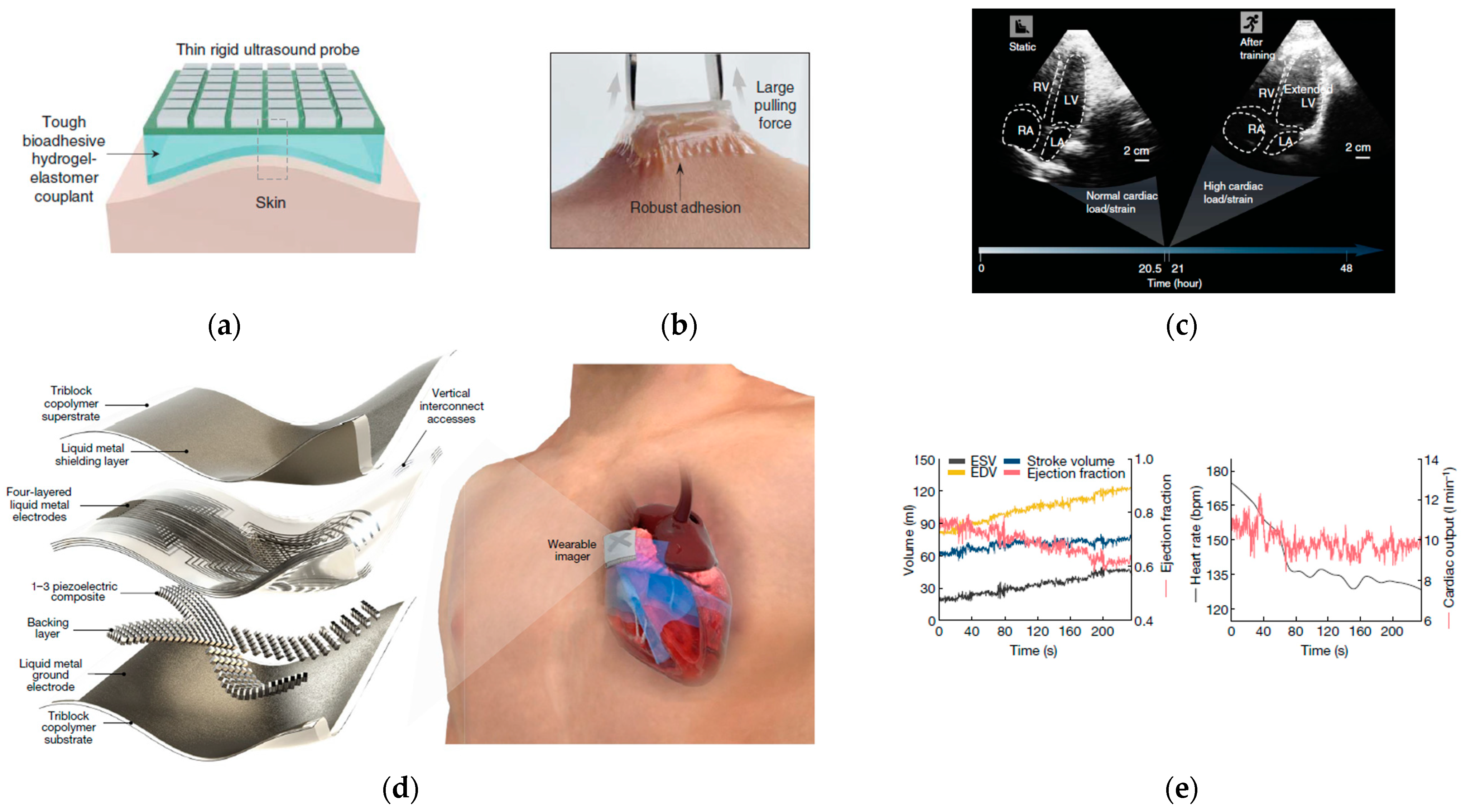
- Hu, H.; Huang, H.; Li, M.; Gao, X.; Yin, L.; Qi, R.; Wu, R.S.; Chen, X.; Ma, Y.; Shi, K.; et al. A wearable cardiac ultrasound imager. Nature 2023, 613, 667–675. [Google Scholar] [CrossRef]
- Carter, M.; Shieh, J.C. Guide to Research Techniques in Neuroscience; Academic Press: Cambridge, MA, USA, 2015. [Google Scholar]
- Michael, J.; Shea, M. Electrocardiography (ECG; EKG). Available online: https://www.merckmanuals.com/home/heart-and-blood-vessel-disorders/diagnosis-of-heart-and-blood-vessel-disorders/electrocardiography (accessed on 1 January 2023).
- Experiments, J.o.V. Acquisition and Analysis of an ECG (Electrocardiography) Signal. Available online: https://www.jove.com/science-education/10473 (accessed on 1 January 2023).
- The McGill Physiology Virtual Lab—Cardiovascular Laboratory. Available online: https://www.medicine.mcgill.ca/physio/vlab/cardio/ECGbasics.htm (accessed on 1 January 2023).
- Biel, L.; Pettersson, O.; Philipson, L.; Wide, P. ECG analysis: A new approach in human identification. IEEE Trans. Instrum. Meas. 2001, 50, 808–812. [Google Scholar] [CrossRef]
- Sharma, L.N.; Tripathy, R.K.; Dandapat, S. Multiscale Energy and Eigenspace Approach to Detection and Localization of Myocardial Infarction. IEEE Trans. Biomed. Eng. 2015, 62, 1827–1837. [Google Scholar] [CrossRef] [PubMed]
- Luz, E.J.d.S.; Schwartz, W.R.; Cámara-Chávez, G.; Menotti, D. ECG-based heartbeat classification for arrhythmia detection: A survey. Comput. Methods Programs Biomed. 2016, 127, 144–164. [Google Scholar] [CrossRef] [PubMed]
- Stamkopoulos, T.; Diamantaras, K.; Maglaveras, N.; Strintzis, M. ECG analysis using nonlinear PCA neural networks for ischemia detection. IEEE Trans. Signal Process. 1998, 46, 3058–3067. [Google Scholar] [CrossRef]
- Bacharova, L.M.; Schocken, D.; H Estes, E.; Strauss, D. The role of ECG in the diagnosis of left ventricular hypertrophy. Curr. Cardiol. Rev. 2014, 10, 257–261. [Google Scholar] [CrossRef] [PubMed]
- Bredahl, K.; Eldrup, N.; Meyer, C.; Eiberg, J.; Sillesen, H. Reproducibility of ECG-gated ultrasound diameter assessment of small abdominal aortic aneurysms. Eur. J. Vasc. Endovasc. Surg. 2013, 45, 235–240. [Google Scholar] [CrossRef] [PubMed]
- Empson, R. FDA Approves AliveCor’s Heart Monitor for the Iphone. Available online: https://techcrunch.com/2012/12/04/mobile-health-moves-forward-fda-approves-alivecors-heart-monitor-for-the-iphone/ (accessed on 1 January 2023).
- Wasimuddin, M.; Elleithy, K.; Abuzneid, A.S.; Faezipour, M.; Abuzaghleh, O. Stages-Based ECG Signal Analysis From Traditional Signal Processing to Machine Learning Approaches: A Survey. IEEE Access 2020, 8, 177782–177803. [Google Scholar] [CrossRef]
- Malmivuo, J.; Plonsey, R. Bioelectromagnetism. 13. Electroencephalography; Oxford Univ. Press: Oxford, UK, 1995; pp. 247–264. [Google Scholar]
- Fürbass, F. EEG Monitoring Based on Automatic Detection of Seizures and Repetitive Discharges. Doctoral Dissertation, Technische Universität Wien, Vienna, Austria, 2017. [Google Scholar]
- Pramanik, P.K.D.; Upadhyaya, B.K.; Pal, S.; Pal, T. Chapter 1—Internet of things, smart sensors, and pervasive systems: Enabling connected and pervasive healthcare. In Healthcare Data Analytics and Management; Dey, N., Ashour, A.S., Bhatt, C., James Fong, S., Eds.; Academic Press: Cambridge, MA, USA, 2019; pp. 1–58. [Google Scholar] [CrossRef]
- Gibbs, F.A.; Gibbs, E.L. Atlas of Electroencephalography; F. A. Gibbs, Boston City Hospital: Boston, MA, USA, 1941. [Google Scholar]
- Kanda, P.A.d.M.; Anghinah, R.; Smidth, M.T.; Silva, J.M. The clinical use of quantitative EEG in cognitive disorders. Dement. Neuropsychol. 2009, 3, 195–203. [Google Scholar] [CrossRef] [PubMed]
- Noachtar, S.; Rémi, J. The role of EEG in epilepsy: A critical review. Epilepsy Behav. 2009, 15, 22–33. [Google Scholar] [CrossRef]
- Selvam, V.S.; Devi, S.S. Analysis of spectral features of EEG signal in brain tumor condition. Meas. Sci. Rev. 2015, 15, 219. [Google Scholar] [CrossRef]
- Nuwer, M.R.; Hovda, D.A.; Schrader, L.M.; Vespa, P.M. Routine and quantitative EEG in mild traumatic brain injury. Clin. Neurophysiol. 2005, 116, 2001–2025. [Google Scholar] [CrossRef]
- Han, C.-X.; Wang, J.; Yi, G.-S.; Che, Y.-Q. Investigation of EEG abnormalities in the early stage of Parkinson’s disease. Cogn. Neurodyn. 2013, 7, 351–359. [Google Scholar] [CrossRef]
- Sartori, M.; Gizzi, L.; Lloyd, D.; Farina, D. A musculoskeletal model of human locomotion driven by a low dimensional set of impulsive excitation primitives. Front. Comput. Neurosci. 2013, 7, 79. [Google Scholar] [CrossRef]
- Picard, N.; Strick, P.L. Motor Areas of the Medial Wall: A Review of Their Location and Functional Activation. Cereb. Cortex 1996, 6, 342–353. [Google Scholar] [CrossRef] [PubMed]
- Azim, M.R.; Haque, S.A.; Amin, M.S.; Latif, T. Analysis of EEG and EMG signals for detection of Sleep Disordered Breathing events. In Proceedings of the International Conference on Electrical & Computer Engineering (ICECE 2010), Dhaka, Bangladesh, 18–20 December 2010; pp. 646–649. [Google Scholar]
- Adel, T.; Stashuk, D. Clinical Quantitative Electromyography. In Electrodiagnosis in New Frontiers of Clinical Research; IntechOpen: London, UK, 22 May 2013. [Google Scholar]
- Fuglsang-Frederiksen, A. The role of different EMG methods in evaluating myopathy. Clin. Neurophysiol. 2006, 117, 1173–1189. [Google Scholar] [CrossRef]
- Furby, A.; Behin, A.; Lefaucheur, J.-P.; Beauvais, K.; Marcorelles, P.; Mussini, J.-M.; Bassez, G.; Créange, A.; Eymard, B.; Pénisson-Besnier, I. Late-onset cervicoscapular muscle atrophy and weakness after radiotherapy for Hodgkin disease: A case series. J. Neurol. Neurosurg. Psychiatry 2010, 81, 101–104. [Google Scholar] [CrossRef] [PubMed]
- Sakakibara, R.; Uchiyama, T.; Yamanishi, T.; Kishi, M. Sphincter EMG as a diagnostic tool in autonomic disorders. Clin. Auton. Res. 2009, 19, 20–31. [Google Scholar] [CrossRef]
- Mills, K.R. The basics of electromyography. J. Neurol. Neurosurg. Psychiatry 2005, 76, ii32–ii35. [Google Scholar] [CrossRef] [PubMed]
- Griffiths, I.R.; Duncan, I.D. The use of electromyography and nerve conduction studies in the evaluation of lower motor neurone disease or injury. J. Small Anim. Pract. 1978, 19, 329–340. [Google Scholar] [CrossRef] [PubMed]
- Acharya, U.R.; Oh, S.L.; Hagiwara, Y.; Tan, J.H.; Adeli, H. Deep convolutional neural network for the automated detection and diagnosis of seizure using EEG signals. Comput. Biol. Med. 2018, 100, 270–278. [Google Scholar] [CrossRef]
- Ferree, T.C.; Luu, P.; Russell, G.S.; Tucker, D.M. Scalp electrode impedance, infection risk, and EEG data quality. Clin. Neurophysiol. 2001, 112, 536–544. [Google Scholar] [CrossRef]
- Zepeda-Carapia, I.; Marquez-Espinoza, A.; Alvarado-Serrano, C. Measurement of Skin-Electrode Impedance for a 12-Lead Electrocardiogram; 2005, Measurement of skin-electrode impedance for a 12-lead electrocardiogram. In Proceedings of the 2005 2nd International Conference on Electrical and Electronics Engineering, Mexico City, Mexico, 7–9 September 2005; pp. 193–195. [Google Scholar] [CrossRef]
- Jung, H.; Moon, J.; Baek, D.; Lee, J.; Choi, Y.; Hong, J.; Lee, S. CNT/PDMS Composite Flexible Dry Electrodesfor Long-Term ECG Monitoring. IEEE Trans. Biomed. Eng. 2012, 59, 1472–1479. [Google Scholar] [CrossRef]
- Da Silva, L.F.; Dillard, D.A.; Blackman, B.; Adams, R.D. Testing Adhesive Joints: Best Practices; John Wiley & Sons: Hoboken, NJ, USA, 2012. [Google Scholar]
- Izadi, H.; Penlidis, A. Polymeric Bio-Inspired Dry Adhesives: Van der Waals or Electrostatic Interactions? Macromol. React. Eng. 2013, 7, 588–608. [Google Scholar] [CrossRef]
- Horn, R.G.; Smith, D.T. Contact Electrification and Adhesion between Dissimilar Materials. Science 1992, 256, 362–364. [Google Scholar] [CrossRef]
- Gu, Z.; Li, S.; Zhang, F.; Wang, S. Understanding Surface Adhesion in Nature: A Peeling Model. Adv. Sci. 2016, 3, 1500327. [Google Scholar] [CrossRef]
- Pressure Sensitive. Available online: https://www.adhesives.org/adhesives-sealants/adhesives-sealants-overview/adhesive-technologies/pressure-sensitive (accessed on 1 January 2023).
- Ritter, P.; Villringer, A. Simultaneous EEG–fMRI. Neurosci. Biobehav. Rev. 2006, 30, 823–838. [Google Scholar] [CrossRef] [PubMed]
- Maughan, R.J.; Shirreffs, S.M.; Watson, P. Exercise, Heat, Hydration and the Brain. J. Am. Coll. Nutr. 2007, 26, 604S–612S. [Google Scholar] [CrossRef] [PubMed]
- Clark, R.P. Chapter 4 Human Skin Temperature and Convective Heat Loss. In Studies in Environmental Science; Cena, K., Clark, J.A., Eds.; Elsevier: Amsterdam, The Netherlands, 1981; Volume 10, pp. 57–76. [Google Scholar]
- Ring, E.F.J.; Phillips, B. Recent Advances in Medical Thermology; Springer: Berlin/Heidelberg, Germany, 1984; pp. 177–183. [Google Scholar] [CrossRef]
- Chatterjee, S.; Kyriacou, P.A. Monte Carlo Analysis of Optical Interactions in Reflectance and Transmittance Finger Photoplethysmography. Sensors 2019, 19, 789. [Google Scholar] [CrossRef]
- Helfman, T.; Ovington, L.; Falanga, V. Occlusive dressings and wound healing. Clin. Dermatol. 1994, 12, 121–127. [Google Scholar] [CrossRef]
- Toutouzas, K.; Benetos, G.; Drakopoulou, M.; Deligianni, C.; Spengos, K.; Stefanadis, C.; Siores, E.; Tousoulis, D. Incremental predictive value of carotid inflammation in acute ischemic stroke. Stroke 2015, 46, 272–274. [Google Scholar] [CrossRef]
- Gautherie, M. Thermopathology of breast cancer: Measurement and analysis of in vivo temperature and blood flow. Ann. N. Y. Acad. Sci. 1980, 335, 383–415. [Google Scholar] [CrossRef]
- Anbar, M. Clinical thermal imaging today. IEEE Eng. Med. Biol. Mag. 1998, 17, 25–33. [Google Scholar] [CrossRef]
- Lawson, R. Implications of surface temperatures in the diagnosis of breast cancer. Can. Med. Assoc. J. 1956, 75, 309–311. [Google Scholar] [PubMed]
- Kennedy, D.A.; Lee, T.; Seely, D. A Comparative Review of Thermography as a Breast Cancer Screening Technique. Integr. Cancer Ther. 2009, 8, 9–16. [Google Scholar] [CrossRef]
- Kenefick, R.W.; Sollanek, K.J.; Charkoudian, N.; Sawka, M.N. Impact of skin temperature and hydration on plasma volume responses during exercise. J. Appl. Physiol. 2014, 117, 413–420. [Google Scholar] [CrossRef]
- Sze, S.M.; Ng, K.K. Physics of Semiconductor Devices; John Wiley & Sons: Hoboken, NJ, USA, 2006. [Google Scholar]
- Seebeck, T.J. Magnetische Polarisation der Metalle und erze Durch Temperatur-Differenz; Wilhelm Engelmann: Berlin, Germany, 1895. [Google Scholar]
- Ioffe, A.F. Semiconductor Thermoelements and Thermoelectric Cooling; Infosearch Limited: London, UK, 1957. [Google Scholar]
- Li, J.-F.; Liu, W.-S.; Zhao, L.-D.; Zhou, M. High-performance nanostructured thermoelectric materials. NPG Asia Mater. 2010, 2, 152–158. [Google Scholar] [CrossRef]
- Dames, C. Solid-State Thermal Rectification With Existing Bulk Materials. J. Heat Transf. 2009, 131, 061301–061307. [Google Scholar] [CrossRef]
- Grove, A.S. Physics and Technology of Semiconductor Devices; Wiley: Hoboken, NJ, USA, 1967. [Google Scholar]
- Wehmeyer, G.; Yabuki, T.; Monachon, C.; Wu, J.; Dames, C. Thermal diodes, regulators, and switches: Physical mechanisms and potential applications. Appl. Phys. Rev. 2017, 4, 041304. [Google Scholar] [CrossRef]
- Tremper, K.K. Pulse Oximetry. CHEST 1989, 95, 713–715. [Google Scholar] [CrossRef]
- Millasseau, S.C.; Ritter, J.M.; Takazawa, K.; Chowienczyk, P.J. Contour analysis of the photoplethysmographic pulse measured at the finger. J. Hypertens. 2006, 24, 1449–1456. [Google Scholar] [CrossRef]
- Nitzan, M.; Khanokh, B.; Slovik, Y. The difference in pulse transit time to the toe and finger measured by photoplethysmography. Physiol. Meas. 2001, 23, 85. [Google Scholar] [CrossRef]
- Selvaraj, N.; Jaryal, A.; Santhosh, J.; Deepak, K.K.; Anand, S. Assessment of heart rate variability derived from finger-tip photoplethysmography as compared to electrocardiography. J. Med. Eng. Technol. 2008, 32, 479–484. [Google Scholar] [CrossRef]
- Millasseau, S.; Kelly, R.; Ritter, J.; Chowienczyk, P. Determination of age-related increases in large artery stiffness by digital pulse contour analysis. Clin. Sci. 2002, 103, 371–377. [Google Scholar] [CrossRef]
- Lax, H.; Feinberg, A.W.; Cohen, B.M. Studies of the arterial pulse wave: I. The normal pulse wave and its modification in the presence of human arteriosclerosis. J. Chronic Dis. 1956, 3, 618–631. [Google Scholar] [CrossRef]
- Imanaga, I.; Hara, H.; Koyanagi, S.; Tanaka, K. Correlation between Wave Components of the Second Derivative of Plethysmogram and Arterial Distensibility. Jpn. Heart J. 1998, 39, 775–784. [Google Scholar] [CrossRef]
- Takazawa, K.; Tanaka, N.; Fujita, M.; Matsuoka, O.; Saiki, T.; Aikawa, M.; Tamura, S.; Ibukiyama, C. Assessment of Vasoactive Agents and Vascular Aging by the Second Derivative of Photoplethysmogram Waveform. Hypertension 1998, 32, 365–370. [Google Scholar] [CrossRef] [PubMed]
- Hashimoto, J.; Chonan, K.; Aoki, Y.; Nishimura, T.; Ohkubo, T.; Hozawa, A.; Suzuki, M.; Matsubara, M.; Michimata, M.; Araki, T. Pulse wave velocity and the second derivative of the finger photoplethysmogram in treated hypertensive patients: Their relationship and associating factors. J. Hypertens. 2002, 20, 2415–2422. [Google Scholar] [CrossRef]
- Otsuka, T.; Kawada, T.; Katsumata, M.; Ibuki, C. Utility of Second Derivative of the Finger Photoplethysmogram for the Estimation of the Risk of Coronary Heart Disease in the General Population. Circ. J. 2006, 70, 304–310. [Google Scholar] [CrossRef] [PubMed]
- Bortolotto, L.A.; Blacher, J.; Kondo, T.; Takazawa, K.; Safar, M.E. Assessment of vascular aging and atherosclerosis in hypertensive subjects: Second derivative of photoplethysmogram versus pulse wave velocity. Am. J. Hypertens. 2000, 13, 165–171. [Google Scholar] [CrossRef] [PubMed]
- Lee, J.; Matsumura, K.; Yamakoshi, K.-i.; Rolfe, P.; Tanaka, S.; Yamakoshi, T. Comparison between red, green and blue light reflection photoplethysmography for heart rate monitoring during motion. In Proceedings of the 2013 35th Annual International Conference of the IEEE Engineering in Medicine and Biology Society (EMBC), Osaka, Japan, 3–7 July 2013; pp. 1724–1727. [Google Scholar]
- Elsamnah, F.; Bilgaiyan, A.; Affiq, M.; Shim, C.-H.; Ishidai, H.; Hattori, R. Comparative Design Study for Power Reduction in Organic Optoelectronic Pulse Meter Sensor. Biosensors 2019, 9, 48. [Google Scholar] [CrossRef] [PubMed]
- Chung, H.; Dai, T.; Sharma, S.K.; Huang, Y.-Y.; Carroll, J.D.; Hamblin, M.R. The Nuts and Bolts of Low-level Laser (Light) Therapy. Ann. Biomed. Eng. 2012, 40, 516–533. [Google Scholar] [CrossRef]
- Ash, C.; Dubec, M.; Donne, K.; Bashford, T. Effect of wavelength and beam width on penetration in light-tissue interaction using computational methods. Lasers Med. Sci. 2017, 32, 1909–1918. [Google Scholar] [CrossRef]
- Minolta, K. Basic Understanding of the Pulse Oximeter. How to Read spo2; Konica Minolta Sensing, Inc.: Ramsey, NJ, USA, 2006. [Google Scholar]
- Steve Underwood, V.C. A Single-Chip Pulsoximeter Design Using the MSP430. Available online: http://www.ti.com/lit/an/slaa274b/slaa274b.pdf (accessed on 1 January 2023).
- Smiths Medical PM, I. How Can SpO2 Readings Differ from Manufacturer to Manufacturer? Available online: https://www.medexsupply.com/images/How%20can%20SpO2%20readings%20differ.pdf (accessed on 1 January 2023).
- Design, E.C. Measuring Heart Rate and Blood Oxygen Levels for Portable Medical and Wearable Devices. Available online: https://embeddedcomputing.com/application/healthcare/measuring-heart-rate-and-blood-oxygen-levels-for-portable-medical-and-wearable-devices (accessed on 1 January 2023).
- Tamura, T.; Maeda, Y.; Sekine, M.; Yoshida, M. Wearable Photoplethysmographic Sensors—Past and Present. Electronics 2014, 3, 282–302. [Google Scholar] [CrossRef]
- Castaneda, D.; Esparza, A.; Ghamari, M.; Soltanpur, C.; Nazeran, H. A review on wearable photoplethysmography sensors and their potential future applications in health care. Int. J. Biosens. Bioelectron. 2018, 4, 195–202. [Google Scholar] [CrossRef]
- Mendelson, Y.; Pujary, C. Measurement site and photodetector size considerations in optimizing power consumption of a wearable reflectance pulse oximeter. In Proceedings of the 25th Annual International Conference of the IEEE Engineering in Medicine and Biology Society (IEEE Cat. No.03CH37439), Cancun, Mexico, 17–21 September 2003; Volume 3014, pp. 3016–3019. [Google Scholar]
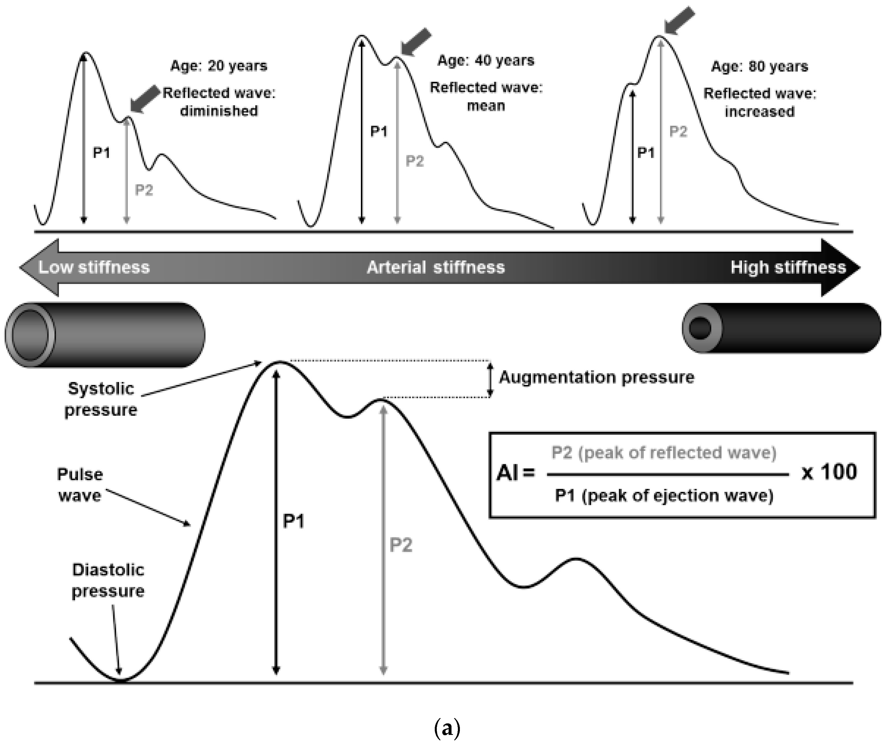
- O’Rourke, M.F.; Hashimoto, J. Mechanical Factors in Arterial Aging. A Clin. Perspect. 2007, 50, 1–13. [Google Scholar] [CrossRef]
- McEniery, C.M.; Cockcroft, J.R.; Roman, M.J.; Franklin, S.S.; Wilkinson, I.B. Central blood pressure: Current evidence and clinical importance. Eur. Heart J. 2014, 35, 1719–1725. [Google Scholar] [CrossRef] [PubMed]
- Salvi, P.; Grillo, A.; Parati, G. Noninvasive estimation of central blood pressure and analysis of pulse waves by applanation tonometry. Hypertens. Res. 2015, 38, 646–648. [Google Scholar] [CrossRef] [PubMed]
- Smulyan, H.; Siddiqui, D.S.; Carlson, R.J.; London, G.M.; Safar, M.E. Clinical Utility of Aortic Pulses and Pressures Calculated From Applanated Radial-Artery Pulses. Hypertension 2003, 42, 150–155. [Google Scholar] [CrossRef] [PubMed]
- Takazawa, K.; Kobayashi, H.; Shindo, N.; Tanaka, N.; Yamashina, A. Relationship between Radial and Central Arterial Pulse Wave and Evaluation of Central Aortic Pressure Using the Radial Arterial Pulse Wave. Hypertens. Res. 2007, 30, 219. [Google Scholar] [CrossRef] [PubMed]
- da Fonseca, L.J.S.; Ant, M.; Rabelo, L.A. Radial applanation tonometry as an adjuvant tool in the noninvasive arterial stiffness and blood pressure assessment. World J. Cardiovasc. Dis. 2014, 2014, 45642. [Google Scholar] [CrossRef]
- Gratz, I.; Deal, E.; Spitz, F.; Baruch, M.; Allen, I.E.; Seaman, J.E.; Pukenas, E.; Jean, S. Continuous Non-invasive finger cuff CareTaker® comparable to invasive intra-arterial pressure in patients undergoing major intra-abdominal surgery. BMC Anesth. 2017, 17, 48. [Google Scholar] [CrossRef]
- Huang, C.-M.; Chang, H.-C.; Kao, S.-T.; Li, T.-C.; Wei, C.-C.; Chen, C.; Liao, Y.-T.; Chen, F.-J. Radial Pressure Pulse and Heart Rate Variability in Heat- and Cold-Stressed Humans. Evid.-Based Complement. Altern. Med. 2011, 2011, 751317. [Google Scholar] [CrossRef]
- Cattell, M.A.; Anderson, J.C.; Hasleton, P.S. Age-related changes in amounts and concentrations of collagen and elastin in normotensive human thoracic aorta. Clin. Chim. Acta 1996, 245, 73–84. [Google Scholar] [CrossRef]
- Karamanoglu, M.; Feneley, M.P. Late systolic pressure augmentation: Role of left ventricular outflow patterns. Am. J. Physiol.-Heart Circ. Physiol. 1999, 277, H481–H487. [Google Scholar] [CrossRef]
- Shimizu, M.; Kario, K. Review: Role of the augmentation index in hypertension. Ther. Adv. Cardiovasc. Dis. 2008, 2, 25–35. [Google Scholar] [CrossRef]
- Mora-Urda, A.I.; Molina, M.d.C.B.; Mill, J.G.; Montero-López, P. Carotid-Femoral Pulse Wave Velocity in Healthy Spanish Children: Reference Percentile Curves. J. Clin. Hypertens. 2017, 19, 227–234. [Google Scholar] [CrossRef] [PubMed]
- Obeid, H.; Ouedraogo, V.; Hallab, M. Arterial Stiffness: A New Biomarker to be Measured. J. Arch. Mil. Med. 2017, 5, e13204. [Google Scholar] [CrossRef]
- Laurent, S.; Cockcroft, J.; Van Bortel, L.; Boutouyrie, P.; Giannattasio, C.; Hayoz, D.; Pannier, B.; Vlachopoulos, C.; Wilkinson, I.; Struijker-Boudier, H.; et al. Expert consensus document on arterial stiffness: Methodological issues and clinical applications. Eur. Heart J. 2006, 27, 2588–2605. [Google Scholar] [CrossRef]
- Kim, H.-L.; Kim, S.-H. Pulse Wave Velocity in Atherosclerosis. Front. Cardiovasc. Med. 2019, 6, 41. [Google Scholar] [CrossRef] [PubMed]
- Van Bortel, L.M.; Laurent, S.; Boutouyrie, P.; Chowienczyk, P.; Cruickshank, J.; De Backer, T.; Filipovsky, J.; Huybrechts, S.; Mattace-Raso, F.U.; Protogerou, A.D. Expert consensus document on the measurement of aortic stiffness in daily practice using carotid-femoral pulse wave velocity. J. Hypertens. 2012, 30, 445–448. [Google Scholar] [CrossRef]
- Greenland, P.; Alpert, J.S.; Beller, G.A.; Benjamin, E.J.; Budoff, M.J.; Fayad, Z.A.; Foster, E.; Hlatky, M.A.; Hodgson, J.M.; Kushner, F.G.; et al. 2010 ACCF/AHA Guideline for Assessment of Cardiovascular Risk in Asymptomatic Adults: Executive Summary: A Report of the American College of Cardiology Foundation/American Heart Association Task Force on Practice Guidelines Developed in Collaboration With the American Society of Echocardiography, American Society of Nuclear Cardiology, Society of Atherosclerosis Imaging and Prevention, Society for Cardiovascular Angiography and Interventions, Society of Cardiovascular Computed Tomography, and Society for Cardiovascular Magnetic Resonance. J. Am. Coll. Cardiol. 2010, 56, 2182–2199. [Google Scholar] [CrossRef]
- Rodrigues, L. The In Vivo Biomechanical Testing of the Skin and the Cosmetological Efficacy Claim Support: A Critical Overview. In Cosmetics: Controlled Efficacy Studies and Regulation; Elsner, P., Maibach, H.I., Merk, H.F., Eds.; Springer: Berlin/Heidelberg, Germany, 1999; pp. 197–208. [Google Scholar] [CrossRef]
- Diridollou, S.; Black, D.; Lagarde, J.M.; Gall, Y.; Berson, M.; Vabre, V.; Patat, F.; Vaillant, L. Sex- and site-dependent variations in the thickness and mechanical properties of human skin in vivo. Int. J. Cosmet. Sci. 2000, 22, 421–435. [Google Scholar] [CrossRef]
- Daly, C.H.; Odland, G.F. Age-related changes in the mechanical properties of human skin. J. Investig. Dermatol. 1979, 73, 84–87. [Google Scholar] [CrossRef]
- Es’ haghian, S.; Kennedy, K.M.; Gong, P.; Sampson, D.D.; McLaughlin, R.A.; Kennedy, B.F. Optical palpation in vivo: Imaging human skin lesions using mechanical contrast. J. Biomed. Opt. 2015, 20, 016013. [Google Scholar] [CrossRef]
- Yuan, J.H.; Shi, Y.; Pharr, M.; Feng, X.; Rogers, J.A.; Huang, Y. A Mechanics Model for Sensors Imperfectly Bonded to the Skin for Determination of the Young’s Moduli of Epidermis and Dermis. J. Appl. Mech. 2016, 83, 0845011–0845013. [Google Scholar] [CrossRef]
- Wang, C.; Qi, B.; Lin, M.; Zhang, Z.; Makihata, M.; Liu, B.; Zhou, S.; Huang, Y.-h.; Hu, H.; Gu, Y.; et al. Continuous monitoring of deep-tissue haemodynamics with stretchable ultrasonic phased arrays. Nat. Biomed. Eng. 2021, 5, 749–758. [Google Scholar] [CrossRef] [PubMed]
- Pang, C.; Lee, G.-Y.; Kim, T.-i.; Kim, S.M.; Kim, H.N.; Ahn, S.-H.; Suh, K.-Y. A flexible and highly sensitive strain-gauge sensor using reversible interlocking of nanofibres. Nat. Mater. 2012, 11, 795. [Google Scholar] [CrossRef] [PubMed]
- Stassi, S.; Cauda, V.; Canavese, G.; Pirri, C.F. Flexible tactile sensing based on piezoresistive composites: A review. Sensors 2014, 14, 5296–5332. [Google Scholar] [CrossRef] [PubMed]
- Li, G.; Chen, D.; Li, C.; Liu, W.; Liu, H. Engineered microstructure derived hierarchical deformation of flexible pressure sensor induces a supersensitive piezoresistive property in broad pressure range. Adv. Sci. 2020, 7, 2000154. [Google Scholar] [CrossRef]
- Liu, Y.; Wang, H.; Zhao, W.; Qin, H.; Fang, X. Thermal-performance instability in piezoresistive sensors: Inducement and improvement. Sensors 2016, 16, 1984. [Google Scholar] [CrossRef]
- Li, J.; Fang, L.; Sun, B.; Li, X.; Kang, S.H. Review—Recent Progress in Flexible and Stretchable Piezoresistive Sensors and Their Applications. J. Electrochem. Soc. 2020, 167, 037561. [Google Scholar] [CrossRef]
- Shiba, K.; Imamura, G.; Yoshikawa, G. 4.3—Nanomechanical Sensors. In Biomaterials Nanoarchitectonics; Ebara, M., Ed.; William Andrew Publishing: Norwich, NY, USA, 2016; pp. 177–196. [Google Scholar] [CrossRef]
- Puers, R. Capacitive sensors: When and how to use them. Sens. Actuators A Phys. 1993, 37–38, 93–105. [Google Scholar] [CrossRef]
- Hammock, M.L.; Chortos, A.; Tee, B.C.-K.; Tok, J.B.-H.; Bao, Z. 25th Anniversary Article: The Evolution of Electronic Skin (E-Skin): A Brief History, Design Considerations, and Recent Progress. Adv. Mater. 2013, 25, 5997–6038. [Google Scholar] [CrossRef]
- Pyo, S.; Lee, J.; Bae, K.; Sim, S.; Kim, J. Recent progress in flexible tactile sensors for human-interactive systems: From sensors to advanced applications. Adv. Mater. 2021, 33, 2005902. [Google Scholar] [CrossRef]
- Hanna, F.F.; Yehia, A.A.; Abou-Bakr, A.F. Dielectric properties of styrene—Butadiene rubber/silicon dioxide mixtures. Br. Polym. J. 1973, 5, 83–90. [Google Scholar] [CrossRef]
- Kim, Y.; Lee, J.; Hong, H.; Park, S.; Ryu, W. Self-Powered Wearable Micropyramid Piezoelectric Film Sensor for Real-Time Monitoring of Blood Pressure. Adv. Eng. Mater. 2023, 25, 2200873. [Google Scholar] [CrossRef]
- Zhang, X.; Hillenbrand, J.; Sessler, G.M. Ferroelectrets with improved thermal stability made from fused fluorocarbon layers. J. Appl. Phys. 2007, 101, 054114. [Google Scholar] [CrossRef]
- Cotton, D.P.J.; Chappell, P.H.; Cranny, A.; White, N.M.; Beeby, S.P. A Novel Thick-Film Piezoelectric Slip Sensor for a Prosthetic Hand. IEEE Sens. J. 2007, 7, 752–761. [Google Scholar] [CrossRef]
- Xu, S.; Qin, Y.; Xu, C.; Wei, Y.; Yang, R.; Wang, Z.L. Self-powered nanowire devices. Nat. Nanotechnol. 2010, 5, 366–373. [Google Scholar] [CrossRef] [PubMed]
- Yothers, M.P.; Browder, A.E.; Bumm, L.A. Real-space post-processing correction of thermal drift and piezoelectric actuator nonlinearities in scanning tunneling microscope images. Rev. Sci. Instrum. 2017, 88, 013708. [Google Scholar] [CrossRef] [PubMed]
- Carovac, A.; Smajlovic, F.; Junuzovic, D. Application of ultrasound in medicine. Acta Inf. Med. 2011, 19, 168–171. [Google Scholar] [CrossRef]
- Bhatta, A.K.; Keyal, U.; Liu, Y. Application of high frequency ultrasound in dermatology. Discov. Med. 2018, 26, 237–242. [Google Scholar]
- Wang, C.; Li, X.; Hu, H.; Zhang, L.; Huang, Z.; Lin, M.; Zhang, Z.; Yin, Z.; Huang, B.; Gong, H.; et al. Monitoring of the central blood pressure waveform via a conformal ultrasonic device. Nat. Biomed. Eng. 2018, 2, 687–695. [Google Scholar] [CrossRef]
- Simonsen, J.G.; Axmon, A.; Nordander, C.; Arvidsson, I. Neck and upper extremity pain in sonographers–associations with occupational factors. Appl. Ergon. 2017, 58, 245–253. [Google Scholar] [CrossRef]
- Heres, H.M.; Sjoerdsma, M.; Schoots, T.; Rutten, M.C.; van de Vosse, F.N.; Lopata, R.G. Image acquisition stability of fixated musculoskeletal sonography in an exercise setting: A quantitative analysis and comparison with freehand acquisition. J. Med. Ultrason. 2020, 47, 47–56. [Google Scholar] [CrossRef]
- Craig, S.S.; Craig, S.A.; Ganio, M.S.; Maresh, C.M.; Horrace, G.; da Costa, K.-A.; Zeisel, S.H. The betaine content of sweat from adolescent females. J. Int. Soc. Sport. Nutr. 2010, 7, 3. [Google Scholar] [CrossRef] [PubMed]
- Heikenfeld, J. Technological leap for sweat sensing. Nature 2016, 529, 475. [Google Scholar] [CrossRef] [PubMed]
- Robertson, W.G.; Marshall, R.W.; Bowers, G.N. Ionized Calcium in Body Fluids. CRC Crit. Rev. Clin. Lab. Sci. 1981, 15, 85–125. [Google Scholar] [CrossRef]
- Patterson, M.J.; Galloway, S.D.R.; Nimmo, M.A. Variations in regional sweat composition in normal human males. Exp. Physiol. 2001, 85, 869–875. [Google Scholar] [CrossRef]
- Sonner, Z.; Wilder, E.; Heikenfeld, J.; Kasting, G.; Beyette, F.; Swaile, D.; Sherman, F.; Joyce, J.; Hagen, J.; Kelley-Loughnane, N.; et al. The microfluidics of the eccrine sweat gland, including biomarker partitioning, transport, and biosensing implications. Biomicrofluidics 2015, 9, 031301. [Google Scholar] [CrossRef]
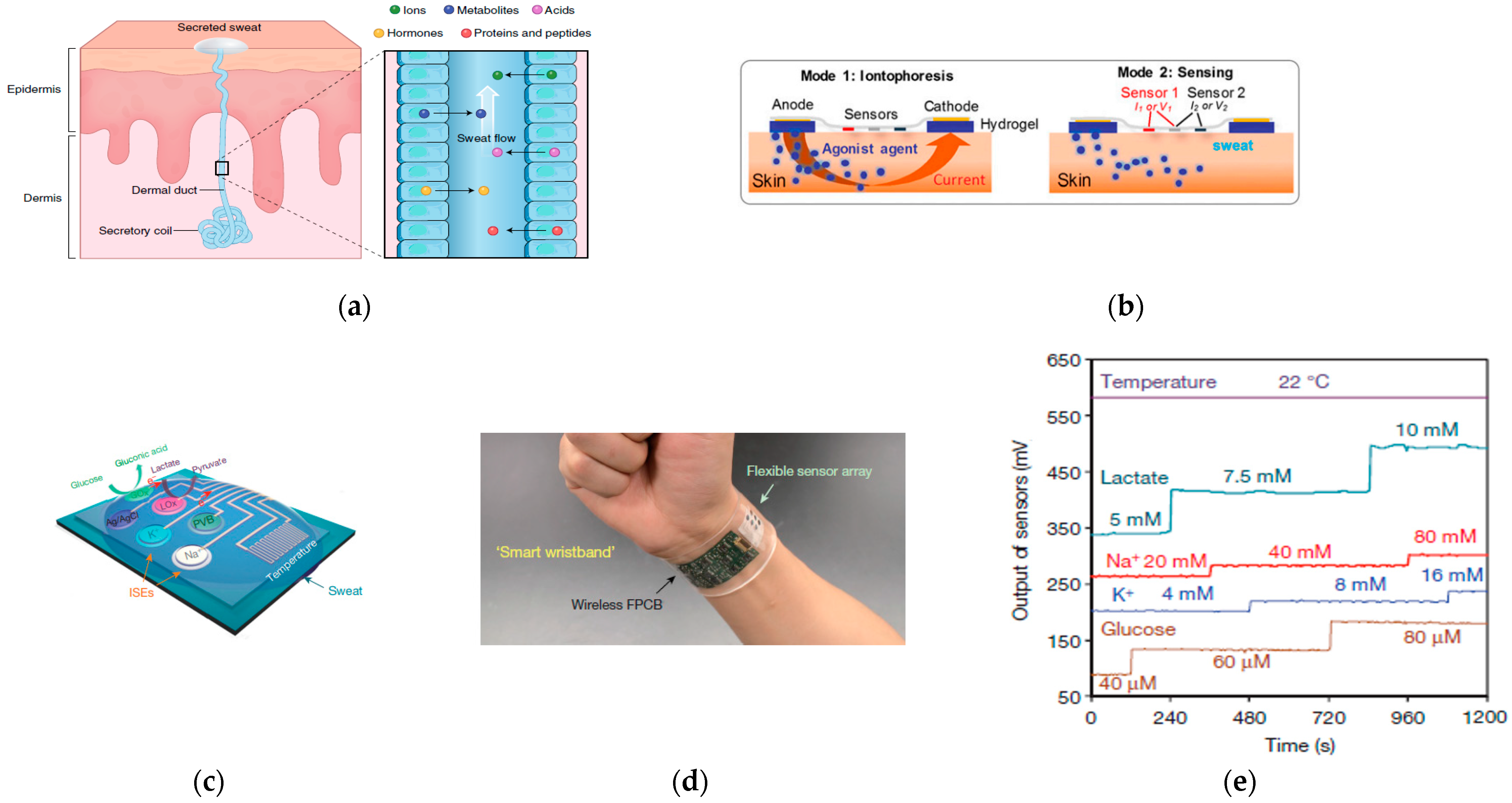
- Emaminejad, S.; Gao, W.; Wu, E.; Davies, Z.A.; Yin Yin Nyein, H.; Challa, S.; Ryan, S.P.; Fahad, H.M.; Chen, K.; Shahpar, Z.; et al. Autonomous sweat extraction and analysis applied to cystic fibrosis and glucose monitoring using a fully integrated wearable platform. Proc. Natl. Acad. Sci. USA 2017, 114, 4625–4630. [Google Scholar] [CrossRef] [PubMed]
- Gonzalo-Ruiz, J.; Mas, R.; de Haro, C.; Cabruja, E.; Camero, R.; Alonso-Lomillo, M.A.; Muñoz, F.J. Early determination of cystic fibrosis by electrochemical chloride quantification in sweat. Biosens. Bioelectron. 2009, 24, 1788–1791. [Google Scholar] [CrossRef]
- Davis, P.B.; Drumm, M.; Konstan, M.W. Cystic fibrosis. Am. J. Respir. Crit. Care Med. 1996, 154, 1229–1256. [Google Scholar] [CrossRef]
- Malhotra, M.S.; Sridharan, K.; Venkataswamy, Y. Potassium losses in sweat under heat stress. Aviat Space Env. Med. 1976, 47, 503–504. [Google Scholar]
- Consolazio, C.F.; Matoush, L.O.; Nelson, R.A.; Hackler, L.R.; Preston, E.E. Relationship Between Calcium in Sweat, Calcium Balance, and Calcium Requirements. J. Nutr. 1962, 78, 78–88. [Google Scholar] [CrossRef]
- Kehayoglou, A.K.; Holdsworth, C.D.; Agnew, J.E.; Whelton, M.J.; Sherlock, S. Bone Disease and Calcium Absorption IN Primary Biliary Cirrhosis: With Special Reference to Vitamin-D Therapy. Lancet 1968, 291, 715–719. [Google Scholar] [CrossRef]
- Bouillon, R.; Auwerx, J.; Dekeyser, L.; Fevery, J.; Lissens, W.; De Moor, P. Serum Vitamin D Metabolites and Their Binding Protein in Patients with Liver Cirrhosis. J. Clin. Endocrinol. Metab. 1984, 59, 86–89. [Google Scholar] [CrossRef] [PubMed]
- Gogusev, J.; Duchambon, P.; Hory, B.; Giovannini, M.; Goureau, Y.; Sarfati, E.; Drüeke, T.B. Depressed expression of calcium receptor in parathyroid gland tissue of patients with hyperparathyroidism. Kidney Int. 1997, 51, 328–336. [Google Scholar] [CrossRef] [PubMed]
- Shawcross, D.L.; Shabbir, S.S.; Taylor, N.J.; Hughes, R.D. Ammonia and the neutrophil in the pathogenesis of hepatic encephalopathy in cirrhosis. Hepatology 2010, 51, 1062–1069. [Google Scholar] [CrossRef]
- Bariya, M.; Yin Yin Nyein, H.; Javey, A. Wearable sweat sensors. Nat. Electron. 2018, 1, 160–171. [Google Scholar] [CrossRef]
- Schmid-Wendtner, M.H.; Korting, H.C. The pH of the Skin Surface and Its Impact on the Barrier Function. Ski. Pharmacol. Physiol. 2006, 19, 296–302. [Google Scholar] [CrossRef]
- Polliack, A.; Taylor, R.; Bader, D. Sweat analysis following pressure ischaemia in a group of debilitated subjects. J. Rehabil. Res. Dev. 1997, 34, 303–308. [Google Scholar] [PubMed]
- Green, J.M.; Bishop, P.A.; Muir, I.H.; McLester Jr, J.R.; Heath, H.E. Effects of High and Low Blood Lactate Concentrations on Sweat Lactate Response. Int. J. Sport. Med. 2000, 21, 556–560. [Google Scholar] [CrossRef]
- Correlation Between Sweat Glucose and Blood Glucose in Subjects with Diabetes. Diabetes Technol. Ther. 2012, 14, 398–402. [CrossRef]
- Fraga, C.G. Relevance, essentiality and toxicity of trace elements in human health. Mol. Asp. Med. 2005, 26, 235–244. [Google Scholar] [CrossRef]
- Schaefer, M.; Schellenberg, M.; Merle, U.; Weiss, K.H.; Stremmel, W. Wilson protein expression, copper excretion and sweat production in sweat glands of Wilson disease patients and controls. BMC Gastroenterol. 2008, 8, 29. [Google Scholar] [CrossRef] [PubMed]
- Sears, M.E.; Kerr, K.J.; Bray, R.I. Arsenic, Cadmium, Lead, and Mercury in Sweat: A Systematic Review. J. Environ. Public Health 2012, 2012, 10. [Google Scholar] [CrossRef]
- Mudgal, V.; Madaan, N.; Mudgal, A.; Singh, R.; Mishra, S. Effect of toxic metals on human health. Open Nutraceuticals J. 2010, 3, 94–99. [Google Scholar] [CrossRef]
- Bandodkar, A.J.; Molinnus, D.; Mirza, O.; Guinovart, T.; Windmiller, J.R.; Valdés-Ramírez, G.; Andrade, F.J.; Schöning, M.J.; Wang, J. Epidermal tattoo potentiometric sodium sensors with wireless signal transduction for continuous non-invasive sweat monitoring. Biosens. Bioelectron. 2014, 54, 603–609. [Google Scholar] [CrossRef]
- Rose, D.P.; Ratterman, M.E.; Griffin, D.K.; Hou, L.; Kelley-Loughnane, N.; Naik, R.R.; Hagen, J.A.; Papautsky, I.; Heikenfeld, J.C. Adhesive RFID Sensor Patch for Monitoring of Sweat Electrolytes. IEEE Trans. Biomed. Eng. 2015, 62, 1457–1465. [Google Scholar] [CrossRef]
- Anastasova, S.; Crewther, B.; Bembnowicz, P.; Curto, V.; Ip, H.M.D.; Rosa, B.; Yang, G.-Z. A wearable multisensing patch for continuous sweat monitoring. Biosens. Bioelectron. 2017, 93, 139–145. [Google Scholar] [CrossRef] [PubMed]
- Gao, W.; Emaminejad, S.; Nyein, H.Y.Y.; Challa, S.; Chen, K.; Peck, A.; Fahad, H.M.; Ota, H.; Shiraki, H.; Kiriya, D.; et al. Fully integrated wearable sensor arrays for multiplexed in situ perspiration analysis. Nature 2016, 529, 509. [Google Scholar] [CrossRef] [PubMed]
- Nyein, H.Y.Y.; Gao, W.; Shahpar, Z.; Emaminejad, S.; Challa, S.; Chen, K.; Fahad, H.M.; Tai, L.-C.; Ota, H.; Davis, R.W.; et al. A Wearable Electrochemical Platform for Noninvasive Simultaneous Monitoring of Ca2+ and pH. ACS Nano 2016, 10, 7216–7224. [Google Scholar] [CrossRef]
- Guinovart, T.; Bandodkar, A.J.; Windmiller, J.R.; Andrade, F.J.; Wang, J. A potentiometric tattoo sensor for monitoring ammonium in sweat. Analyst 2013, 138, 7031–7038. [Google Scholar] [CrossRef]
- Gao, W.; Nyein, H.Y.Y.; Shahpar, Z.; Fahad, H.M.; Chen, K.; Emaminejad, S.; Gao, Y.; Tai, L.-C.; Ota, H.; Wu, E.; et al. Wearable Microsensor Array for Multiplexed Heavy Metal Monitoring of Body Fluids. ACS Sens. 2016, 1, 866–874. [Google Scholar] [CrossRef]
- Kim, J.; de Araujo, W.R.; Samek, I.A.; Bandodkar, A.J.; Jia, W.; Brunetti, B.; Paixão, T.R.L.C.; Wang, J. Wearable temporary tattoo sensor for real-time trace metal monitoring in human sweat. Electrochem. Commun. 2015, 51, 41–45. [Google Scholar] [CrossRef]
- Bandodkar, A.J.; Hung, V.W.S.; Jia, W.; Valdés-Ramírez, G.; Windmiller, J.R.; Martinez, A.G.; Ramírez, J.; Chan, G.; Kerman, K.; Wang, J. Tattoo-based potentiometric ion-selective sensors for epidermal pH monitoring. Analyst 2013, 138, 123–128. [Google Scholar] [CrossRef] [PubMed]
- Curto, V.F.; Fay, C.; Coyle, S.; Byrne, R.; O’Toole, C.; Barry, C.; Hughes, S.; Moyna, N.; Diamond, D.; Benito-Lopez, F. Real-time sweat pH monitoring based on a wearable chemical barcode micro-fluidic platform incorporating ionic liquids. Sens. Actuators B Chem. 2012, 171–172, 1327–1334. [Google Scholar] [CrossRef]
- Koh, A.; Kang, D.; Xue, Y.; Lee, S.; Pielak, R.M.; Kim, J.; Hwang, T.; Min, S.; Banks, A.; Bastien, P.; et al. A soft, wearable microfluidic device for the capture, storage, and colorimetric sensing of sweat. Sci. Transl. Med. 2016, 8, ra165–ra366. [Google Scholar] [CrossRef] [PubMed]
- Gao, L.; Zhang, Y.; Malyarchuk, V.; Jia, L.; Jang, K.-I.; Chad Webb, R.; Fu, H.; Shi, Y.; Zhou, G.; Shi, L.; et al. Epidermal photonic devices for quantitative imaging of temperature and thermal transport characteristics of the skin. Nat. Commun. 2014, 5, 4938. [Google Scholar] [CrossRef]
- Jia, W.; Bandodkar, A.J.; Valdés-Ramírez, G.; Windmiller, J.R.; Yang, Z.; Ramírez, J.; Chan, G.; Wang, J. Electrochemical Tattoo Biosensors for Real-Time Noninvasive Lactate Monitoring in Human Perspiration. Anal. Chem. 2013, 85, 6553–6560. [Google Scholar] [CrossRef]
- Khodagholy, D.; Curto, V.F.; Fraser, K.J.; Gurfinkel, M.; Byrne, R.; Diamond, D.; Malliaras, G.G.; Benito-Lopez, F.; Owens, R.M. Organic electrochemical transistor incorporating an ionogel as a solid state electrolyte for lactate sensing. J. Mater. Chem. 2012, 22, 4440–4443. [Google Scholar] [CrossRef]
- Song, K.; Ha, U.; Lee, J.; Bong, K.; Yoo, H. An 87-mA⋅min Iontophoresis Controller IC With Dual-Mode Impedance Sensor for Patch-Type Transdermal Drug Delivery System. IEEE J. Solid-State Circuits 2014, 49, 167–178. [Google Scholar] [CrossRef]
- Zhang, L.; Lerner, S.; Rustrum, W.V.; Hofmann, G.A. Electroporation-mediated topical delivery of vitamin C for cosmetic applications. Bioelectrochem. Bioenerg. 1999, 48, 453–461. [Google Scholar] [CrossRef]
- Kassan, D.G.; Lynch, A.M.; Stiller, M.J. Physical enhancement of dermatologic drug delivery: Iontophoresis and phonophoresis. J. Am. Acad. Dermatol. 1996, 34, 657–666. [Google Scholar] [CrossRef]
- Magistro, C.M. A Preliminary Clinical Report: Hyaluronidase by Iontophoresis: In the Treatment of Edema. Phys. Therapy 1964, 44, 169–175. [Google Scholar] [CrossRef] [PubMed]
- Gunawardena, H.; Harris, N.; Carmichael, C.; McHugh, N.J. Microvascular responses following digital thermal hyperaemia and iontophoresis measured by laser Doppler imaging in idiopathic inflammatory myopathy. Rheumatology 2007, 46, 1483–1486. [Google Scholar] [CrossRef] [PubMed]
- Allwell-Brown, E.; Afuwape, O.; Ayandipo, O.; Alonge, T. Correlation of the association of serum lactate, random blood sugar, and revised trauma score as predictors of outcome in hemodynamically unstable abdominal emergencies. Niger. J. Clin. Pract. 2016, 19, 196–200. [Google Scholar]
- Mitra, A.; Choi, S.; Boshier, P.R.; Razumovskaya-Hough, A.; Belluomo, I.; Spanel, P.; Hanna, G.B. The Human Skin Volatolome: A Systematic Review of Untargeted Mass Spectrometry Analysis. Metabolites 2022, 12, 824. [Google Scholar] [CrossRef]
- Drabińska, N.; Flynn, C.; Ratcliffe, N.; Belluomo, I.; Myridakis, A.; Gould, O.; Fois, M.; Smart, A.; Devine, T.; Costello, B.D.L. A literature survey of all volatiles from healthy human breath and bodily fluids: The human volatilome. J. Breath Res. 2021, 15, 034001. [Google Scholar] [CrossRef]
- Broza, Y.Y.; Zuri, L.; Haick, H. Combined Volatolomics for Monitoring of Human Body Chemistry. Sci. Rep. 2014, 4, 4611. [Google Scholar] [CrossRef] [PubMed]
- Einoch Amor, R.; Nakhleh, M.K.; Barash, O.; Haick, H. Breath analysis of cancer in the present and the future. European Respir. Rev. 2019, 28, 190002. [Google Scholar] [CrossRef]
- Wang, J.; Li, S.; Yi, F.; Zi, Y.; Lin, J.; Wang, X.; Xu, Y.; Wang, Z.L. Sustainably powering wearable electronics solely by biomechanical energy. Nat. Commun. 2016, 7, 12744. [Google Scholar] [CrossRef]
- Jia, W.; Valdés-Ramírez, G.; Bandodkar, A.J.; Windmiller, J.R.; Wang, J. Epidermal Biofuel Cells: Energy Harvesting from Human Perspiration. Angew. Chem. Int. Ed. 2013, 52, 7233–7236. [Google Scholar] [CrossRef]
- Jia, W.; Wang, X.; Imani, S.; Bandodkar, A.J.; Ramírez, J.; Mercier, P.P.; Wang, J. Wearable textile biofuel cells for powering electronics. J. Mater. Chem. A 2014, 2, 18184–18189. [Google Scholar] [CrossRef]
- Bandodkar, A.J.; You, J.-M.; Kim, N.-H.; Gu, Y.; Kumar, R.; Mohan, A.V.; Kurniawan, J.; Imani, S.; Nakagawa, T.; Parish, B. Soft, stretchable, high power density electronic skin-based biofuel cells for scavenging energy from human sweat. Energy Environ. Sci. 2017, 10, 1581–1589. [Google Scholar] [CrossRef]
- Berchmans, S.; Bandodkar, A.J.; Jia, W.; Ramírez, J.; Meng, Y.S.; Wang, J. An epidermal alkaline rechargeable Ag–Zn printable tattoo battery for wearable electronics. J. Mater. Chem. A 2014, 2, 15788–15795. [Google Scholar] [CrossRef]
- El-Kady, M.F.; Strong, V.; Dubin, S.; Kaner, R.B. Laser Scribing of High-Performance and Flexible Graphene-Based Electrochemical Capacitors. Science 2012, 335, 1326–1330. [Google Scholar] [CrossRef] [PubMed]
- Zhai, X.; Jelfs, B.; Chan, R.H.M.; Tin, C. Self-Recalibrating Surface EMG Pattern Recognition for Neuroprosthesis Control Based on Convolutional Neural Network. Front. Neurosci. 2017, 11, 379. [Google Scholar] [CrossRef] [PubMed]
- Special Considerations: Biocompatibility. Available online: https://www.fda.gov/medical-devices/premarket-notification-510k/special-considerations#bio (accessed on 21 December 2018).
- Use of International Standard ISO 10993-1, Biological Evaluation of Medical Devices—Part 1: Evaluation and Testing within a Risk Management Process. Available online: https://www.fda.gov/media/85865/download (accessed on 1 January 2023).
- ISO 10993-1:2009. Biological Evaluation of Medical Devices—Part 1: Evaluation and Testing within a Risk Management Process (15 October 2009). Available online: http://nhiso.com/wp-content/uploads/2018/05/ISO-10993-1-2009.pdf (accessed on 1 January 2023).


| Sensor Classification | Sensing Mechanism | Measurement Signal | Conductive Material | Signal | Measure Locations | Treatment | Substrate | Refs |
|---|---|---|---|---|---|---|---|---|
| Neural electrical sensor | Electrode | ECG | CNT | Voltage | Chest | Cardiology | PEIE/CNT/PDMS | [46] |
| ECG | Commercial 3M electrode | Voltage | Chest and wrist | Cardiology, brain activity, muscle movement | PDMS | [47] | ||
| ECG | Ag microparticles | Voltage | Chest, arm, scalp | Cardiology | PDMS | [5] | ||
| ECG, EMG | Carbon nanofillers | Voltage | Wrist, stomach, ankle | Cardiology, muscle movement | PDMS | [30] | ||
| ECG, EEG, EMG | Cr/Au FS | Voltage/frequency | Arm, neck, forehead, chest, leg | Cardiology, brain activity, muscle movement | Modified silicone (Smooth-on)/PVA | [36] | ||
| EMG | Au FS | Voltage | Arm, prosthetic | Muscle movement, robotic arm control | Ecoflex (Smooth-on)/PVA | [37] | ||
| EEG | Au FS | Voltage | Ear | Brain activity | silicone elastomer/PVA | [48] | ||
| ECG | Au/Ti FS | Voltage | Neck, chest | Cardiology | Adhesive PDMS | [49] | ||
| ECG, EEG, EMG | Cr/Au FS | Voltage | Back, arm, scalp | Cardiology, brain activity, prosthetic control | Silicone bylayer: Adhesive silicone (RT GEL 4642, Bluestar), Ecoflex (00-30 Smooth-on) | [50] | ||
| ECG, EMG | Cr/Au FS with NdFeB | Voltage | Chest, arm, cheek | Cardiology, muscle movement | Adhesive Bluestar Silicones | [51] | ||
| ECG, EEG, EMG | PEDOT:PSS | Voltage | Chest, arm, scalp | Cardiology, muscle movement, brain activity | PEDOT:PSS/ waterborne polyurethane (WPU) /D-sorbitol blend | [2] | ||
| Thermal sensor | Thermal resistance | Temperature | Cu | Resistance | Arm | Wound healing | Ecoflex | [52] |
| Pt | Resistance | Skin | Body temperature | Modified silicone (Smooth-on)/PVA | [36] | |||
| Au | Resistance | Arm | Body temperature | Ecoflex, (Smooth-on)/PVA | [37] | |||
| Au | Resistance | Skin | Temperature beneath 6 mm of skin surface | Ecoflex | [53] | |||
| Ni-NiO-Ni | Resistance | Facial surface | Respiration temperature | PET | [54] | |||
| PEDOT:PSS | Resistance | Skin/hand | Body temperature | PDMS | [55] | |||
| Thermocouple | Cr/Au FS | Voltage | Wrist | Blood flow | Ecoflex | [56] | ||
| Cr/Au FS | Voltage | Cheek | Vascularization, blood flow, stratum corneum thickness, hydration | Ecoflex 00–30 | [57] | |||
| Diode thermal sensor | PIN diode sensor | Voltage | Skin, palm | Body temperature | Silicone elastomer/PVA | [4] | ||
| Photodetector | Photoelectricity | PPG, SO2 | P3HT: PCBM | Voltage | Fingertip | Cardiology | Parylene | [58,59] |
| Mechanical sensor | Piezoresisticity | Blood pulse | PEDOT: PSS | Current | Wrist | Cardiology | PDMS | [60] |
| Blood pulse | Graphene oxide | Resistance | Wrist, fingertip, chest | Cardiology, respiration states | PDMS | [61] | ||
| Blood pulse, static tremor | Graphene oxide | Current | Wrist, fingertip | Cardiology, Early-stage Parkinson’s disease | Polyurethane sponge | [62] | ||
| pulse rate | EGaIn | Voltage | Wrist | Cardiology | PDMS | [63] | ||
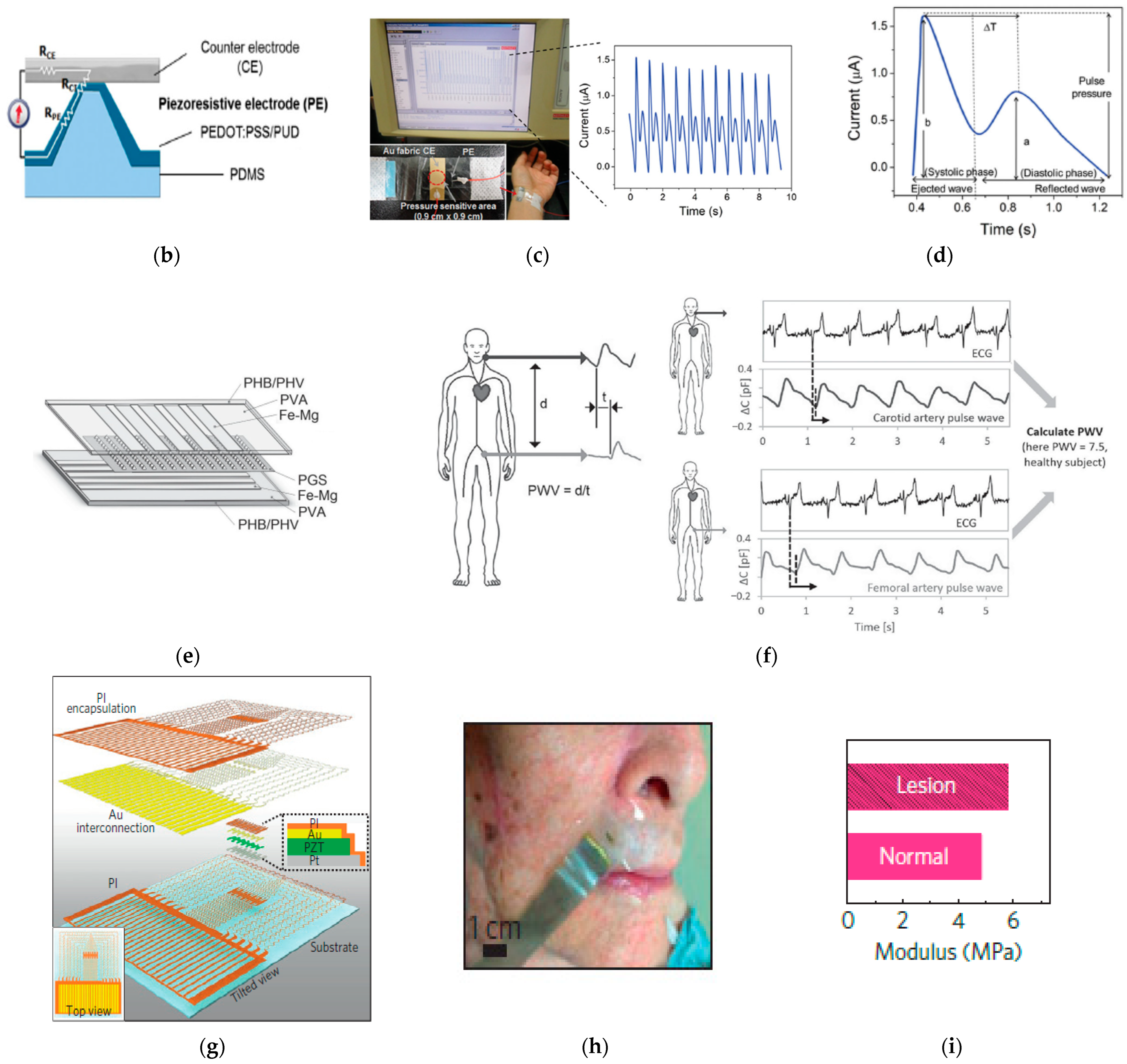
| Capacitance | Pulse rate, PWV | Mg/Fe | Capacitance | Wrist, carotid artery, skin above femoral artery | Cardiology, arterial stiffness | PHB/PHV | [64] | |
| Pulse rate, muscle movement | PEDOT:PSS/ Mxene/P(VDF-TrFE) | Capacitance | Wrist, arm, dermal area of eye and throat | Cardiology, Early-stage Parkinson’s disease | PDMS | [65] | ||
| Pulse rate, physiologic pressure | Cu | Capacitance | Wrist, Intracranial (of mice) | Cardiology, intracranial pressure | SBS | [66] | ||
| Piezoelectricity | Pulse rate, PWV | P(VDF-TrFE) /PEDOT:PSS | Voltage | Wrist, neck | Cardiology, arterial stiffness | PEN | [67] | |
| Pulse rate, PWV | PZT | Current | Wrist, neck, | Cardiology, arterial stiffness | Ecoflex 00-30 | [68] | ||
| Skin modulus | PZT | Voltage | pathologies of skin regions | Dermatology | Ecoflex 00-30 | [69] | ||
| Pulse rate | PDA/BTO/PCVF | Voltage | Wrist, dermal area of throat | Cardiology | PET | [70] | ||
| Ultrasound images | Commercial ultrasound prob | Voltage | Neck, chest | Images of lung, diaphragm, heart, and stomach | Bioadhesive hydrogel elastomer couplant | [32] | ||
| Ultrasound images | PZT-5H | Voltage | Chest | Images of heart | SEBS | [71] |
| Skin-Contact Strategy | Skin-Contact Method/Material | Electrode Material | Impedance | Treatment | Refs |
|---|---|---|---|---|---|
| Van der Waals forces | Hydrogel electrode | Ag/AgCl | 20 kΩ (50 Hz)~75 kΩ (100 Hz) | ECG | [104] |
| CNT/PDMS | CNT | ~100 kΩ (100 Hz) | ECG | [105] | |
| CNT/PEIE/PDMS | CNT | ~145 kΩ (100 Hz) | ECG | [46] | |
| PDMS /in gecko-inspired micropillar structure | Commercial medical 3M electrode | N/A | ECG | [47] | |
| Ag particles in PDMS/ in micropillar structure | Ag | 50 kΩ (10 hz) | ECG, EEG, EMG | [5] | |
| hybrid nanofiller in PDMS/ in gecko-inspired micropillar structure | 1-D CNT and 2-D graphene nanopower | N/A | ECG | [30] | |
| Silicone elastomer/PVA | Cr/Au FS | N/A | ECG, EEG, EMG | [36] | |
| Ecoflex (Smooth-on) /PVA | Au FS | N/A | EMG | [37] | |
| Silicone elastomer/PVA | Au FS | N/A | EEG | [48] | |
| Pressure sensitive adhesive layer | CNT/Adhesive PDMS | Au/Ti/polyimide FS | 241 kΩ (40 Hz) | ECG | [49] |
| Silicone adhesive | Cr/Au FS | 30 kΩ (30 Hz) | ECG, EEG, EEG | [50] | |
| Adhesive Bluestar Silicones / ferromagnetic dipole | Cr/Au FS | <100 kΩ (10 kHz) | ECG, EEG, EMG | [51] | |
| PEDOT:PSS/ waterborne polyurethane (WPU) /D-sorbitol | PEDOT:PSS | 82 at 10 Hz | ECG, EEG, EMG | [2] |
| Pressure Sensor Classification | Sensitivity | Response Time | Stretchability | Operating Voltage | Healthcare Monitoring | Refs |
|---|---|---|---|---|---|---|
| Piezoresistivity | () | 0.2 s | 50% | 0.2 v | Wrist blood wave | [60] |
() | 80–120 ms | N/A | N/A | physiological signals, voice, and motion activities | [61] | |
(); ) | 22 ms | 80% | N/A | Early-stage Parkinson’s disease (tremor of 4–6 Hz) | [62] | |
| – () | 90 ms | Stretching > 200% strain without failure | 30 mV | Cardiology | [63] | |
| Capacitance | (); () | millisecond | Bending radii down to 27 mm, sensitivity remains 80% | N/A | Cardiology, arterial stiffness | [64] |
| 0.15 s | >40 compression (10,000 cycles) | N/A | Cardiology, early-stage Parkinson’s detection, muscle movement, vocalization waves | [65] | ||
| 90 ms | N/A | Nearfield electromagnetic coupling | Cardiology, intracranial pressure | [66] | ||
| Piezoelectricity | 0.1 s | N/A | 3 V | Cardiology, arterial stiffness | [67] | |
| 39 ms (static state)/27 ms (excited state) | Bending angle up to 90° | N/A | Cardiology, voice recognition | [70] | ||
| 0.005 Pa | 0.1 ms | stretching ~30% with effective modulus of ~60 kPa | 1–3 V | Cardiology, arterial stiffness | [68] | |
| (30 1800 kPa) | N/A | Stretching 30% (failure) | 2–5 V | Dermatology | [69] |
| Substrate Material | Device Thickness | Placement Site (Signal) | Exercise/Motion | Adhesion Length | On-Skin Measurement Duration | Ref |
|---|---|---|---|---|---|---|
| 00-30 Ecoflex | Skin (temperature), forehead (EEG), chest (ECG), leg (EMG) | Walking, skin stretching | N/A | 6 h | [36] | |
| Ecoflex 00-30 | N/A | Wrist (blood pulse) | N/A | N/A | 14 s | [68] |
| Ecoflex 00-30 | Skin (dermatology) | N/A | N/A | N/A | [69] | |
| Ecoflex 00-30/ Bluestar 4642 | 0.9 mm | Arm (EMG), scalp (EEG) | Exercise, sleeping and showering, skin stretching | Consistent over several days | 30 s | [50] |
| Ecoflex | Forearm, fingertip (blood flow) | Device compressing | N/A | 30 min | [56] | |
| PDMS | 2 mm | Arm (ECG), scalp (EEG) | Swimming | N/A | 70 s | [5] |
| PDMS | Arm (ECG) | Wrist curl, squat, writing | N/A | 40 s | [30] | |
| PDMS | Wrist (blood pulse) | N/A | N/A | 10 s | [60] | |
| PDMS | Wrist (blood pulse), foot (pressure) | Walking, running, jumping | N/A | 30 s | [61] | |
| PDMS | N/A | Wrist (blood pulse) | Bike riding | N/A | 1400 s | [63] |
| PDMS | Skin (sweat) | Bike riding | N/A | 1–6 h (one-time usage) | [228] | |
| Adhesive PDMS | Chest (ECG) | N/A | N/A | 20 s | [49] | |
| Adhesive Bluestar Silicones | 2 mm | Chest (ECG), arm (EMG), neck (EEG) | N/A | N/A | 20 s | [51] |
| SBS | 0.1 mm | Wrist (blood pulse) | N/A | N/A | 60 s | [66] |
| Silicone elastomer | Ear (EEG) | Washing in soap water | 2 weeks | 3.5 min | [48] | |
| PHB/PHV | 2.4 mm | Wrist (blood pulse, PWV) | N/A | N/A | 15 s | [64] |
| Silicone elastomer/PVA | Palm (temperature) | Device compressing | N/A | 3 h | [4] | |
| PVA | Bicep and tricep, lower back (EEG) | Skin stretching | 2 weeks | 30 s | [37] | |
| PET | Chest (ECG, temperature) | Running | 30 h | 2000 s | [46] | |
| PET | N/A | Skin (sweat) | Bike riding | N/A | 7000 s | [221] |
| PEN | Wrist (blood pulse, PWV) | N/A | N/A | 3 s | [67] | |
| Parylene | ) | N/A | 5 days | 3 s | [59] | |
| Polyurethane sponge | N/A | Wrist (blood pulse), static tremor (Parkinson’s disease diagnosis) | N/A | N/A | 80 s | [62] |
Disclaimer/Publisher’s Note: The statements, opinions and data contained in all publications are solely those of the individual author(s) and contributor(s) and not of MDPI and/or the editor(s). MDPI and/or the editor(s) disclaim responsibility for any injury to people or property resulting from any ideas, methods, instructions or products referred to in the content. |
© 2023 by the authors. Licensee MDPI, Basel, Switzerland. This article is an open access article distributed under the terms and conditions of the Creative Commons Attribution (CC BY) license (https://creativecommons.org/licenses/by/4.0/).
Share and Cite
Mao, P.; Li, H.; Yu, Z. A Review of Skin-Wearable Sensors for Non-Invasive Health Monitoring Applications. Sensors 2023, 23, 3673. https://doi.org/10.3390/s23073673
Mao P, Li H, Yu Z. A Review of Skin-Wearable Sensors for Non-Invasive Health Monitoring Applications. Sensors. 2023; 23(7):3673. https://doi.org/10.3390/s23073673
Chicago/Turabian StyleMao, Pengsu, Haoran Li, and Zhibin Yu. 2023. "A Review of Skin-Wearable Sensors for Non-Invasive Health Monitoring Applications" Sensors 23, no. 7: 3673. https://doi.org/10.3390/s23073673
APA StyleMao, P., Li, H., & Yu, Z. (2023). A Review of Skin-Wearable Sensors for Non-Invasive Health Monitoring Applications. Sensors, 23(7), 3673. https://doi.org/10.3390/s23073673