
A Subtlety of Sizing the Inset Gap Width of a Microstrip Antenna When Built on an Ultra-Thin Substrate in the S-Band


Abstract
1. Introduction
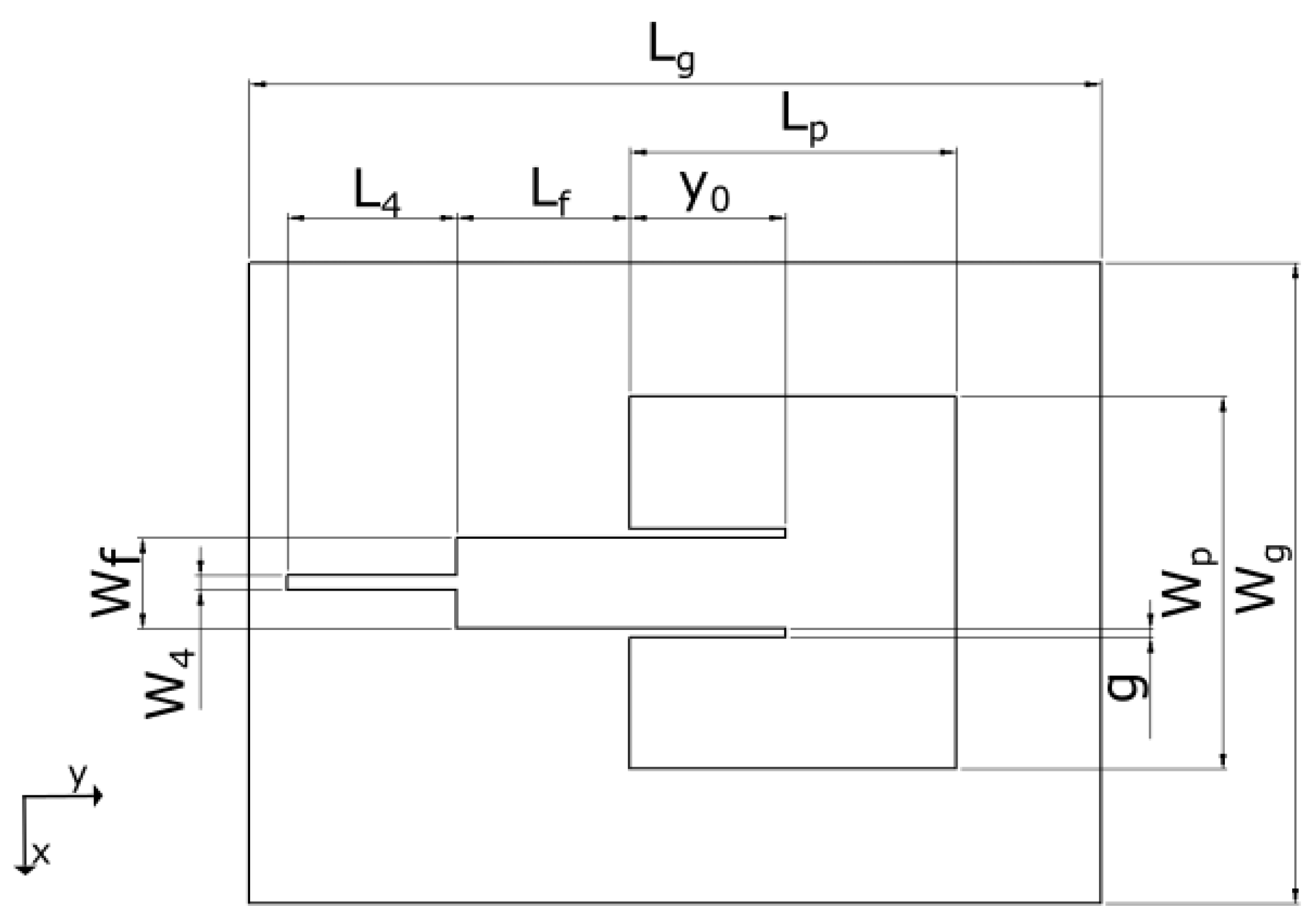
2. Design Considerations for a Rectangular Microstrip Antenna
2.1. Design Expressions
2.2. Difference with Respect to the Antenna Design on a Thicker Substrate
3. The Pretested IRMA Models
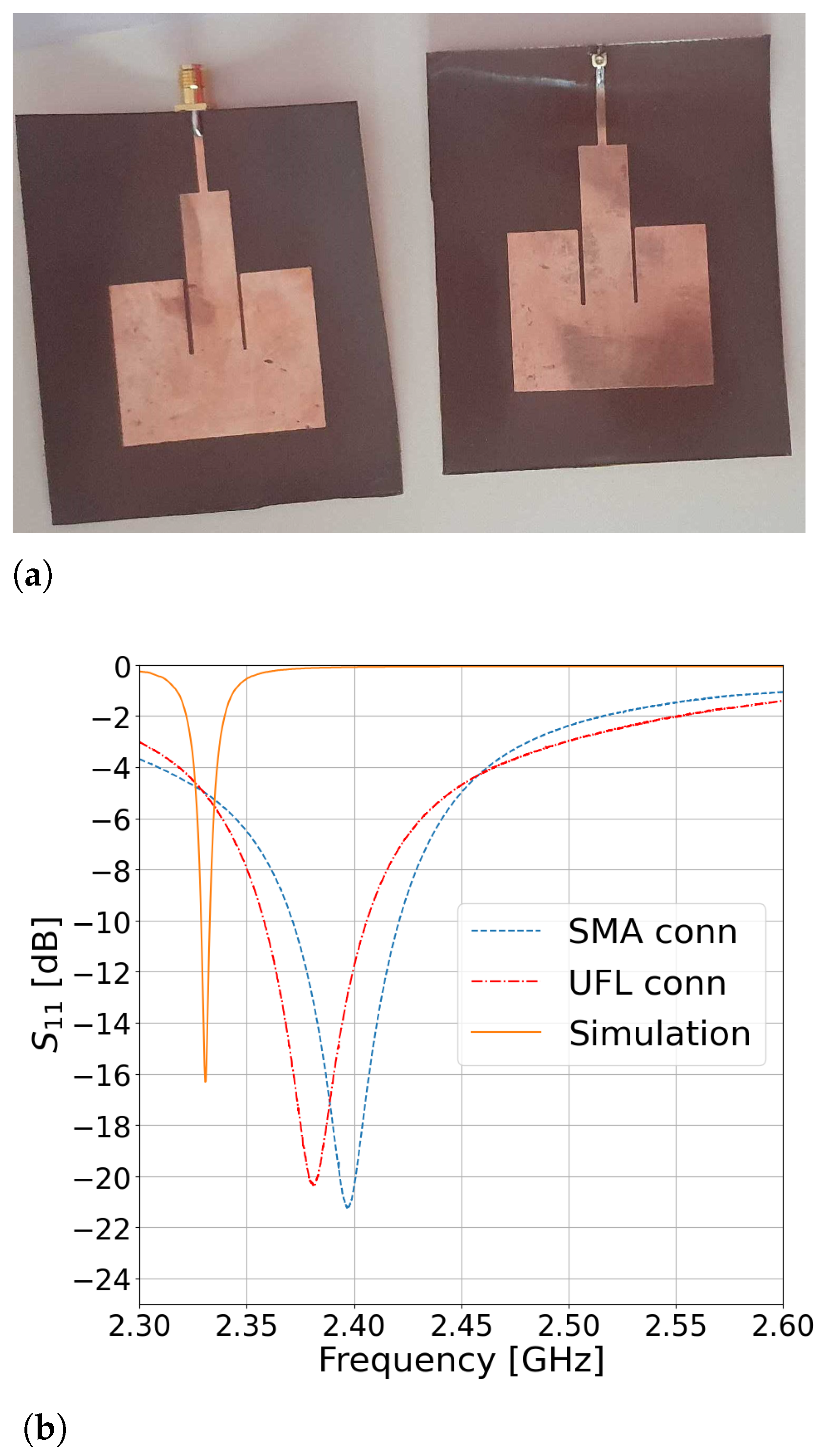
4. A Feasible Pyralux-Based IRMA
4.1. The Impedance Bandwidth
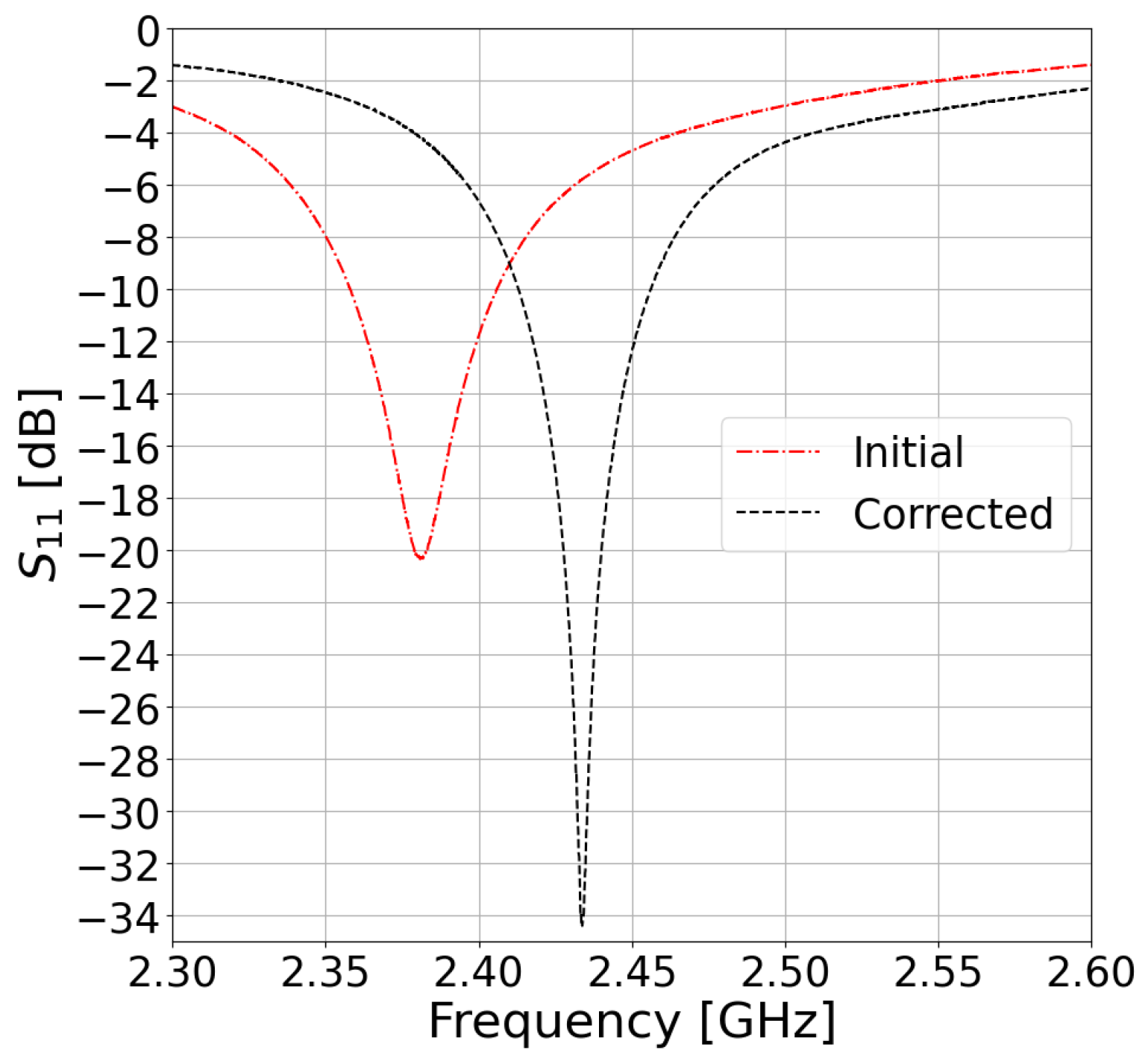
An IRMA with a Corrected Resonant Frequency
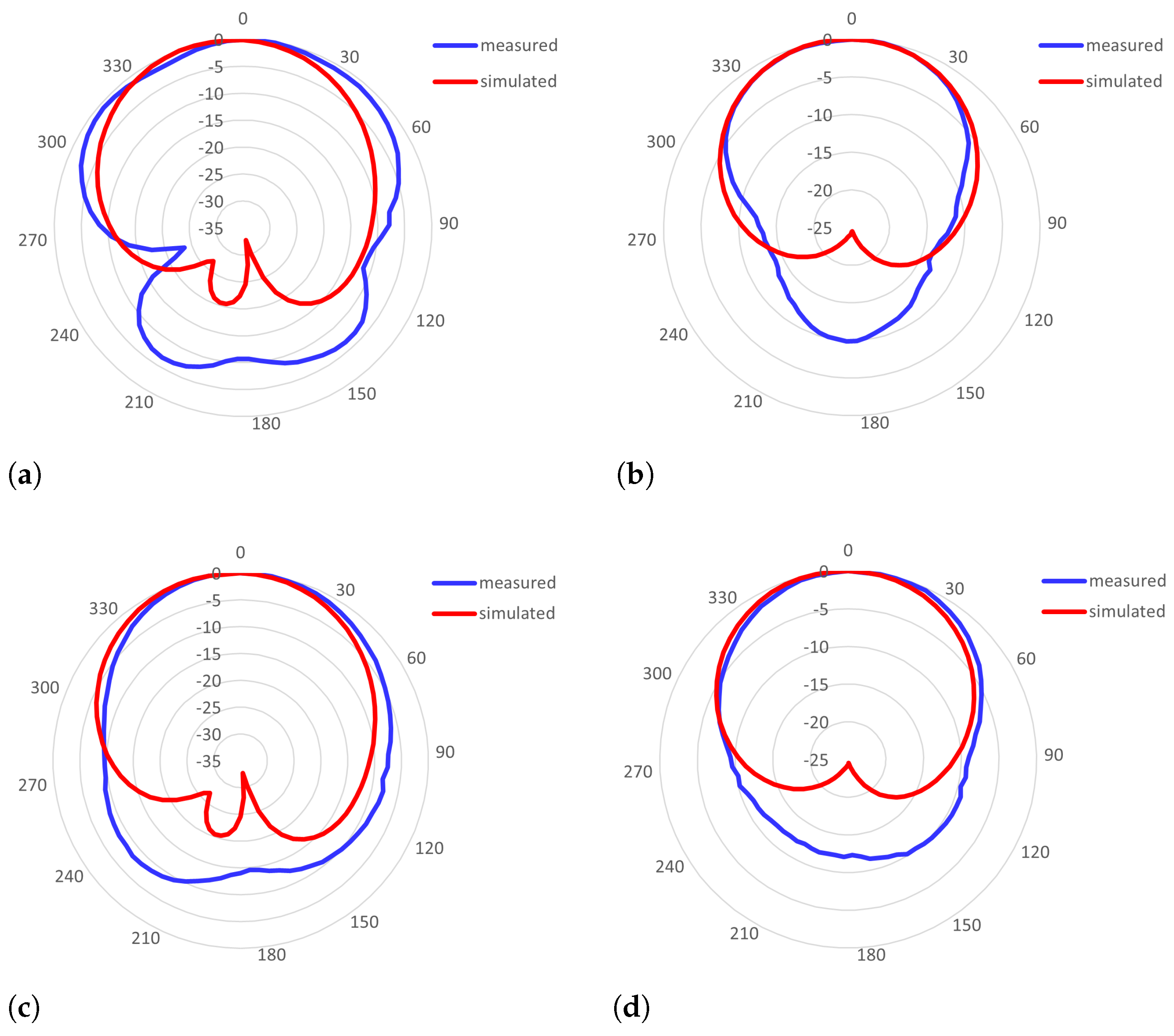
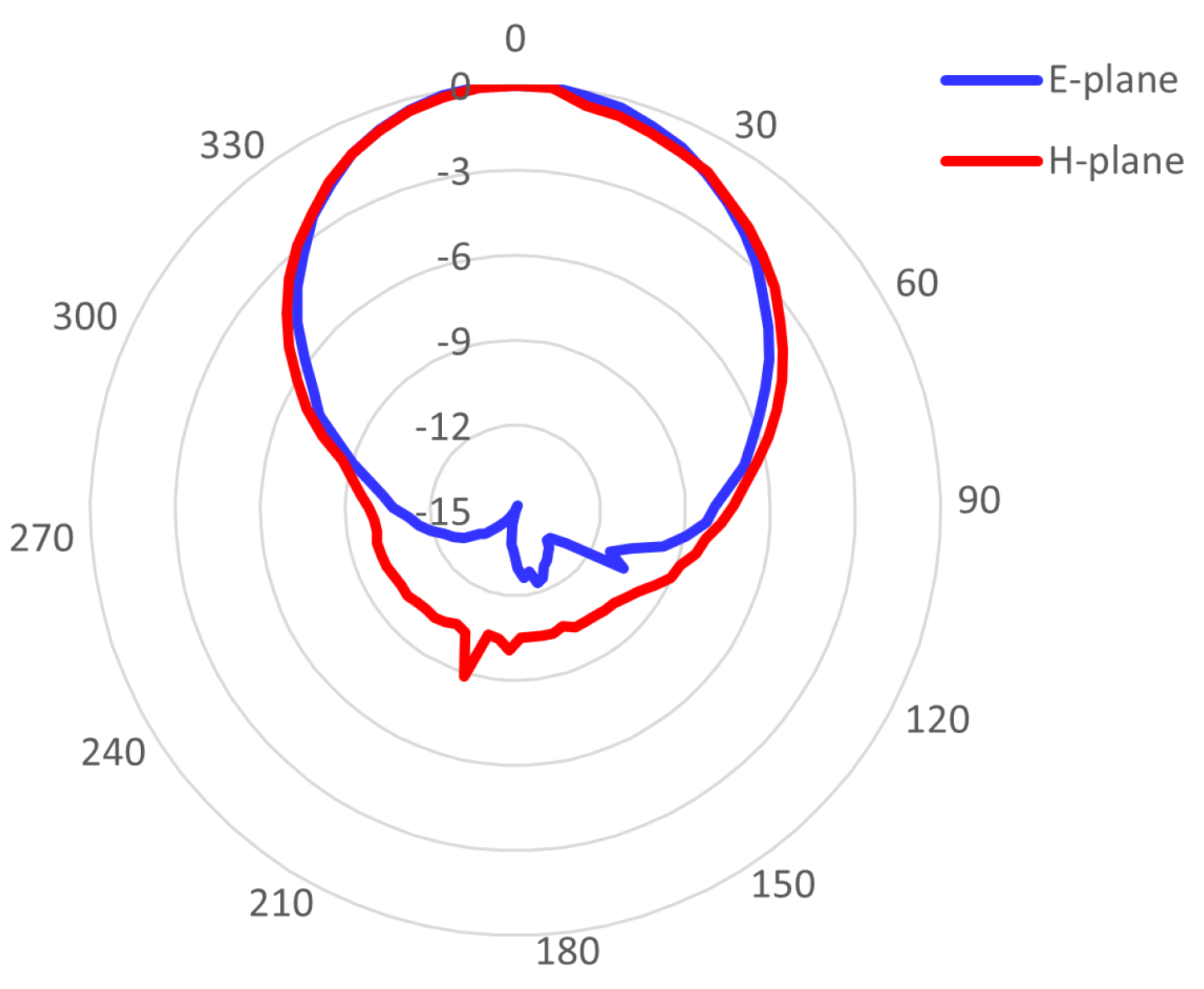
4.2. The Radiation Pattern
5. Discussion
6. Conclusions and Future Work
Author Contributions
Funding
Institutional Review Board Statement
Informed Consent Statement
Data Availability Statement
Acknowledgments
Conflicts of Interest
Abbreviations
| IRMA | inset-fed rectangular microstrip antenna |
| PDMS | polydimethylsiloxane |
| ABS | acrylonitrile butadiene styrene |
| ISM | industrial, scientific, and medical |
References
- Balanis, C.A. Antenna Theory: Analysis and Design, 3rd ed.; Wiley-Interscience: Hoboken, NJ, USA, 2005. [Google Scholar]
- Garg, R.; Bhartia, P.; Bahl, I.; Ittipiboon, A. Microstrip Antenna Design Handbook; Artech House: Norwood, MA, USA, 2001. [Google Scholar]
- Joler, M. Towards a Smart Jacket: Integration of Electronics Challenge. In Proceedings of the 18th International Conference on Sensor Networks and Signal Processing (SNSP 2018), Xi’an, China, 28–31 October 2018. [Google Scholar]
- Trajkovikj, J.; Zürcher, J.F.; Skrivervik, A.K. Soft and flexible antennas on permittivity adjustable PDMS substrates. In Proceedings of the 2012 Loughborough Antennas & Propagation Conference (LAPC), Loughborough, UK, 12–13 November 2012; pp. 1–4. [Google Scholar] [CrossRef]
- Ramadan, M.; Dahle, R. A flexible 2.4 GHz microstrip patch antenna using a 3-D printed tile array design. In Proceedings of the 2017 IEEE MTT-S International Microwave Workshop Series on Advanced Materials and Processes for RF and THz Applications (IMWS-AMP), Pavia, Italy, 20–22 September 2017; pp. 1–3. [Google Scholar] [CrossRef]
- Sakib, N.; Ibrahim, S.N.; Ibn Ibrahimy, M.; Islam, M.S.; Mahfuz, M.M.H. Design of Microstrip Patch Antenna on Rubber Substrate with DGS for WBAN Applications. In Proceedings of the 2020 IEEE Region 10 Symposium (TENSYMP), Dhaka, Bangladesh, 5–7 June 2020; pp. 1050–1053. [Google Scholar] [CrossRef]
- Sreelekshmi, S.; Sankar, S.P. A 2.5 GHz Compact Wearable Microstrip Patch Antenna for off body Wireless Communication in WBANs. In Proceedings of the 2021 Fifth International Conference on I-SMAC (IoT in Social, Mobile, Analytics and Cloud) (I-SMAC), Palladam, India, 11–13 November 2021; pp. 1751–1756. [Google Scholar]
- Vettumperumal, R.; Dhineshbabu, N. Analysis of inset feed microstrip patch antenna on flexible (PVA/CMC/AV) substrate. Mater. Today Proc. 2022, 66, 1633–1637. [Google Scholar] [CrossRef]
- Almazok, S. A flexible and compact 28 GHz inset fed rectangular patch antenna based on circuit in plastic technology for 5G system. J. Alasmarya Univ. 2021, 6, 512–522. [Google Scholar]
- Vettikalladi, H.; Lafond, O.; Himdi, M.; Sarrazin, T.; Rolland, N. 60 GHz membrane supported aperture coupled patch antenna based on FR4 and new thin Pyralux substrate. In Proceedings of the 2012 42nd European Microwave Conference, Amsterdam, The Netherlands, 29 October–1 November 2012; pp. 209–212. [Google Scholar]
- Pozar, D.M. Microwave Engineering, 4th ed.; J. Wiley and Sons: Hoboken, NJ, USA, 2011. [Google Scholar]
- Basilio, L.I.; Khayat, M.A.; Williams, J.T.; Long, S.A. The Dependence of the Input Impedance on Feed Position of Probe and Microstrip Line-Fed Patch Antennas. IEEE Trans. Antennas Propag. 2001, 49, 45–47. [Google Scholar] [CrossRef]
- Samaras, T.; Kouloglou, A.; Sahalos, J.N. A Note on the Impedance Variation with Feed Position of a Rectangular Microstrip-Patch Antenna. IEEE Antennas Propag. Mag. 2004, 46, 90–92. [Google Scholar] [CrossRef]
- Hu, Y.; Jackson, D.R.; Williams, J.T.; Long, S.A.; Komanduri, V.R. Characterization of the Input Impedance of the Inset-Fed Rectangular Microstrip Antenna. IEEE Trans. Antennas Propag. 2008, 56, 3314–3318. [Google Scholar] [CrossRef]
- Liaqat, M. Development of Flexible Microwave Antennas for Breast Cancer Imaging System. Ph.D. Thesis, Universidade Federal de Pernambuco, Recife, Brazil, 2018. [Google Scholar]
- Praludi, T.; Taryanaa, Y.; Paramayudhaa, K.; Prawaraa, B.; Rahayub, Y.; Waela, C.B.A.; Sulaemana, Y.; Sukocoa, B.E.; Sariningruma, R.; Kurniadina, H.; et al. Design of Flexible 3.2 GHz Rectangular Microstrip Patch Antenna for S-Band Communication. J. Elektron. Telekomun. (JET) 2021, 21, 140–145. [Google Scholar] [CrossRef]
- Joler, M.; Kolonić, A.; Boljkovac, M. A Wideband Circularly Polarized Jeans-Based Antenna at 2.45 GHz. Open J. Antennas Propag. 2020, 8, 1–18. [Google Scholar] [CrossRef]
- Joler, M.; Boljkovac, M. A Sleeve-Badge Circularly Polarized Textile Antenna. IEEE Trans. Antennas Propag. 2018, 66, 1576–1579. [Google Scholar] [CrossRef]
- DuPont. Pyralux AP. Available online: https://www.dupont.com/products/pyralux-ap.html (accessed on 15 November 2022).
- Matin, M.A.; Sayeed, A.I. A Design Rule for Inset-fed Rectangular Microstrip Patch Antenna. WSEAS Trans. Commun. 2010, 9, 63–72. [Google Scholar]
- Dassault Systemes. Simulia. CST Studio Suite. Online, 2022. Available online: https://www.3ds.com/products-services/simulia/products/cst-studio-suite/ (accessed on 12 July 2022).
- Gopal, J.S.A.; Dharshini, T.; Jayajith, T.J.P.; Sujanth Narayan, K.; Baskaradas, J.A. Design of Inset Feed Tri-Band Microstrip Patch Antenna for GPS and IRNSS Application. In Proceedings of the 2020 IEEE-HYDCON, Hyderabad, India, 11–12 September 2020; pp. 1–5. [Google Scholar] [CrossRef]
- Baskoro, O.S.; Ardana, I.P.; Sudiarta, P.K.; Munir, A. A 2 × 2 Inset Feed Circular Patch Antenna Array for 1.8 GHz LTE Application. In Proceedings of the 2018 4th International Conference on Wireless and Telematics (ICWT), Nusa Dua, Bali, Indonesia, 12–13 July 2018; pp. 1–4. [Google Scholar] [CrossRef]
- Chaudhary, S.; Binda, P.; Shah, S. An elliptical inset feed patch antenna for UWB applications. In Proceedings of the 2016 IEEE International Conference on Recent Trends in Electronics, Information & Communication Technology (RTEICT), Bengaluru, India, 20–21 May 2016; pp. 646–648. [Google Scholar] [CrossRef]
- Altair. Feko. Available online: https://www.altair.com/feko/ (accessed on 4 December 2022).


| Parameter | Value (mm) |
|---|---|
| 33.69 | |
| 41.75 | |
| 88.05 | |
| 71.75 | |
| 16.06 | |
| g | 1.01 |
| 10.13 | |
| 17.89 | |
| 1.61 | |
| 17.47 |
| Parameter | Value (mm) | Parameter | Value (mm) |
|---|---|---|---|
| 32.76 | g | 1.01 | |
| 40.59 | 10.13 | ||
| 86.13 | 17.39 | ||
| 70.59 | 1.61 | ||
| 15.62 | 16.98 |
| Ref. | (GHz) | Substrate | HPBW () | |||||
|---|---|---|---|---|---|---|---|---|
| Model | Height (mm) | D or G (dBi) | Effic (%) | BW (%) | E-Plane | H-Plane | ||
| [5] | 2.3 | flexible ABS, Ninja-Flex | 2.34 | n/a | n/a | 5.21 | n/a | n/a |
| [6] | 2.45 | rubber (flexible) | 3.42 (G) | 60 (rad) | 4.1 | n/a | n/a | |
| [8] | 2 | polymeric, flexible | 2.55 (G) | 84 (rad) | 2.6 | n/a | n/a | |
| [9] | 28 | polycar-bonate | 0.3 | 5.68 (G) | 69 | 4.2 | 87 | n/a |
| [15] | 2.13 | Pyralux | 0.0508 | −1.8 (D) | n/a | n/a | n/a | |
| [16] | 3.29 | Pyralux FR9111 | 0.025 | 1.4 (G) | n/a | 2.4 | n/a | n/a |
| this | 2.38 | Pyralux AP9131 | 0.075 | 5.8 (D) | 2.67 | 2 | ≥90 | ≥90 |
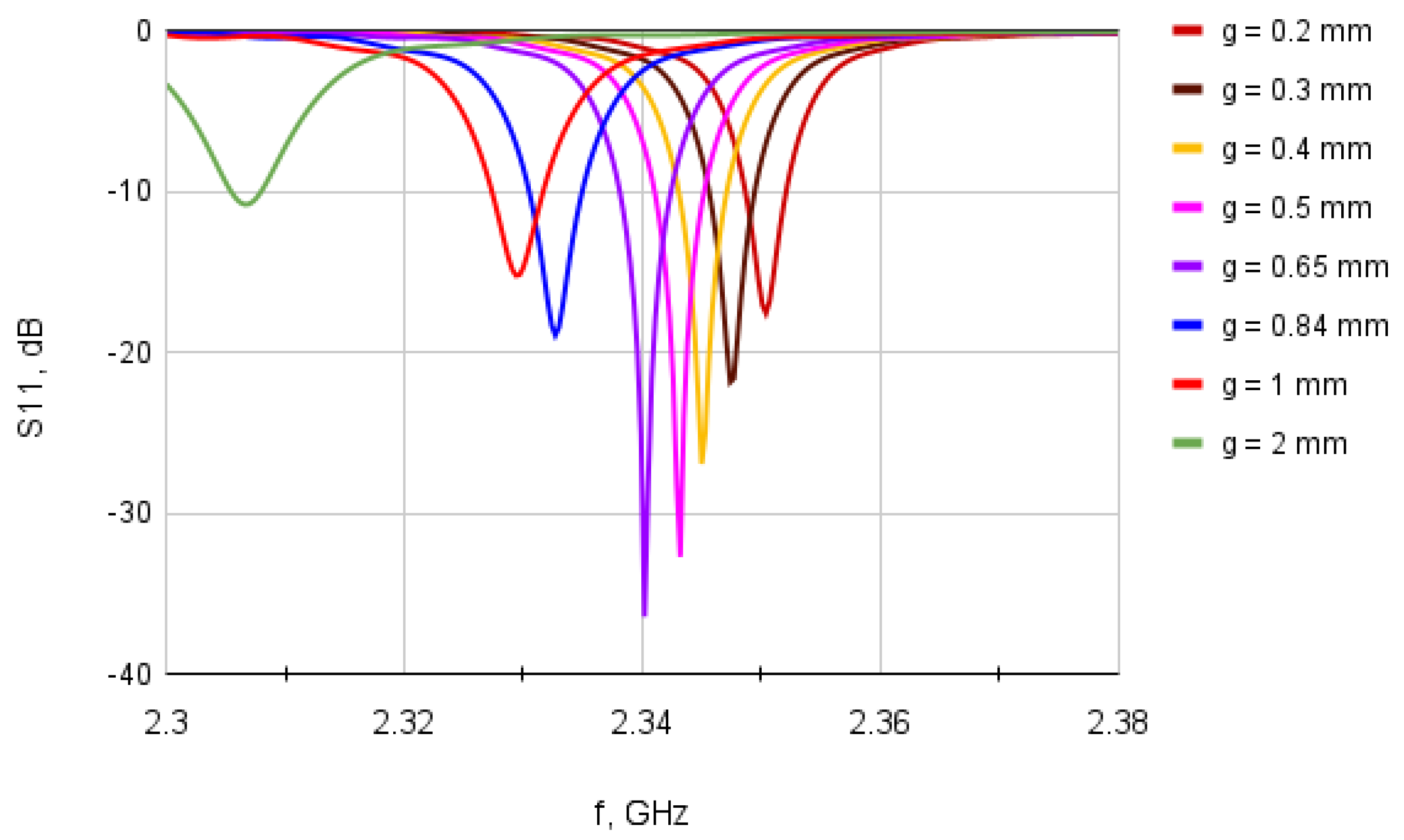
| g (mm) | 2 | 1 | 0.84 | 0.65 | 0.5 | 0.4 | 0.3 | 0.2 |
| 5.07 | 10.13 | 12.06 | 15.58 | 20.26 | 25.33 | 33.77 | 50.65 |
Disclaimer/Publisher’s Note: The statements, opinions and data contained in all publications are solely those of the individual author(s) and contributor(s) and not of MDPI and/or the editor(s). MDPI and/or the editor(s) disclaim responsibility for any injury to people or property resulting from any ideas, methods, instructions or products referred to in the content. |
© 2022 by the authors. Licensee MDPI, Basel, Switzerland. This article is an open access article distributed under the terms and conditions of the Creative Commons Attribution (CC BY) license (https://creativecommons.org/licenses/by/4.0/).
Share and Cite
Joler, M.; Mihalić, L. A Subtlety of Sizing the Inset Gap Width of a Microstrip Antenna When Built on an Ultra-Thin Substrate in the S-Band. Sensors 2023, 23, 213. https://doi.org/10.3390/s23010213
Joler M, Mihalić L. A Subtlety of Sizing the Inset Gap Width of a Microstrip Antenna When Built on an Ultra-Thin Substrate in the S-Band. Sensors. 2023; 23(1):213. https://doi.org/10.3390/s23010213
Chicago/Turabian StyleJoler, Miroslav, and Leo Mihalić. 2023. "A Subtlety of Sizing the Inset Gap Width of a Microstrip Antenna When Built on an Ultra-Thin Substrate in the S-Band" Sensors 23, no. 1: 213. https://doi.org/10.3390/s23010213
APA StyleJoler, M., & Mihalić, L. (2023). A Subtlety of Sizing the Inset Gap Width of a Microstrip Antenna When Built on an Ultra-Thin Substrate in the S-Band. Sensors, 23(1), 213. https://doi.org/10.3390/s23010213