Abstract
In light of the growth in demand for multiband antennas for medical applications, this research proposes a MICS/ISM meander-line microstrip antenna encapsulated in an oblong-shaped pod for use in diagnoses of the gastrointestinal tract. The proposed antenna is operable in the Medical Implant Communication System (MICS) and the Industrial, Scientific and Medical (ISM) bands. The antenna structure consists of a meander-line radiating patch, a flipped-L defected ground plane, and a loading resistor for antenna miniaturization. The MICS/ISM microstrip antenna encapsulated in an oblong-shaped pod was simulated in various lossy-material environments. In addition, the specific absorption rate (SAR) was calculated and compared against the IEEE C95.1 standard. For verification, an antenna prototype was fabricated and experiments carried out in equivalent liquid mixtures, the dielectric constants of which resembled human tissue. The measured impedance bandwidths (|S11| ≤ −10 dB) for the MICS and ISM bands were 398–407 MHz and 2.41–2.48 GHz. The measured antenna gains were −38 dBi and −13 dBi, with a quasi-omnidirectional radiation pattern. The measured SAR was substantially below the maximum safety limits. As a result, the described MICS/ISM microstrip antenna encapsulated in an oblong-shaped pod can be used for real-time gastrointestinal tract diagnosis. The novelty of this work lies in the use of a meander-line microstrip, flipped-L defected ground plane, and loading resistor to miniaturize the antenna and realize the MICS and ISM bands.
1. Introduction
Recent decades have witnessed rapid growth in the adoption of wireless communications technologies in the medical domain, especially those operable in the microwave frequency band [1,2,3,4,5,6,7,8]. In the medical field, wireless technology currently has four applications: therapeutic, sensing, imaging, and telemedicine applications. The therapeutic operating frequency is predominantly for remedial and diagnostic purposes, such as cardiac ablation and cancer therapy [1,2,3]. The sensing and imaging frequency bands are used in in vitro and in vivo diagnoses and magnetic resonance imaging (MRI) [1,2,3], and the telemedicine frequency is for health-care provision and medical consultation [4,5,6,7,8].
There are four universal microwave frequency bands for wireless communications in the health and medical domains: the Medical Implant Communication System (MICS, 401–406 MHz); the Wireless Medical Telemetry Service (WMTS, 1427–1432 MHz); the Wireless Body Area Network (WBAN, 2360–2400 MHz); and the Industrial, Scientific and Medical (ISM) bands (2.4–2.5 GHz) [8,9,10]. In practice, medically implantable and/or ingestible antennas should be small, operable at the medical frequency bands, and harmless to humans.
In [11], a 3D-spiral small antenna operable in the MICS band with a 225.5 MHz bandwidth was proposed for biomedical telemetry. The antenna structure consists of a spiral short-circuit, folded rectangular patch on a double-layer substrate (Teflon and ceramic) with dimensions of 14 × 14 × 15 mm (W × L × H). In [12], the authors proposed an implantable slot dipole conformal antenna operable in the ISM bands, embedded in biocompatible polydimethylsiloxane (PDMS) for total size reduction. The specific absorption rate (SAR) of the antenna in the human muscle tissue liquid was also calculated.
In [13], a planar inverted-F antenna (PIFA) was proposed to enhance the antenna bandwidth in the MICS band. The proposed PIFA can achieve 120 MHz bandwidth and is operable in the 353–473 MHz frequency band. A compact broadband antenna using a triple-layer substrate has been proposed for the MICS band (402 MHz), and the antenna can achieve an impedance bandwidth of 50 MHz [14]. The aforementioned antennas [11,12,13,14] are single-band antennas for medical applications.
Modern medical applications nevertheless demand two or more frequency bands. As a result, a dual folded dipole antenna fed with a coplanar waveguide, with dimensions of 25 × 34 × 2.5 mm, has been proposed [15]. This antenna can achieve impedance matching in the WMTS (1.4–1.43 GHz) and ISM (2.4–2.48 GHz) bands. In [16], an anti-spiral antenna fed with an L-shaped transmission line, operable in the MICS and ISM bands, was fabricated using a Rogers 3210 substrate (dielectric constant of 10.2), with dimensions of 15 × 15 × 1.92 mm. A tri-band slot PIFA, operable in the MICS, WMTS, and ISM bands, was reported to achieve bandwidths of 16 MHz, 100 MHz, and 200 MHz, respectively [17]. The tri-band antenna is comparably bulky and suffers from transmission overburden. Nonetheless, multiband antennas are better for medical applications than single-band ones.
In addition, the electromagnetic properties of the surrounding environment have an effect on the in-body antenna characteristics. In [18], the analytical results for a Hertz dipole embedded in a lossy multilayer spherical body were presented. The dyadic theory of Green’s function was employed. The proposed method can be used for in-body antennas with spherical boundaries. A low-profile, conformal microstrip antenna has been proposed for in-body capsule applications [19]. This proposed conformal antenna is operable at the center frequency of 434 MHz, with a bandwidth of 16 MHz. The experimental results validated the impedance detuning caused by the high permittivity of the surrounding biological environment. In [20], the stepped-impedance resonator (SIR) technique and dielectric-loaded with ceramic shell and pure water inner filling were employed to miniaturize the antenna. It was simulated in a body model containing nine dispersive tissues. Detuning effects were found in this proposed antenna. An inward-directed antenna for the gastrointestinal, operable at a center frequency of 2.45 GHz, has also been investigated. The antenna characteristics were analyzed at different locations in the torso [21].
This research thus proposes an MICS/ISM meander-line microstrip antenna encapsulated in an oblong-shaped pod for medical applications, specifically for use in diagnoses of the gastrointestinal tract. The proposed microstrip antenna is operable in the MICS and ISM bands and its structure consists of a meander-line radiating patch, a flipped-L defected ground plane, and a loading resistor for antenna miniaturization. The MICS/ISM microstrip antenna encapsulated in the pod was simulated in different lossy-material environments: in a pseudo-muscular cubicle, a multilayer spherical body-parts model, and a quasi-human body. The specific absorption rate of the quasi-human body was determined and compared against the IEEE C95.1 standard. For validation, an antenna prototype was fabricated and experiments carried out in equivalent liquid mixtures, the dielectric constants of which resembled human tissue. The advantages of the proposed meander-line microstrip antenna include its dual-band operation (MICS/ISM bands), relatively small size, and low cost due to the use of one single layer of substrate. The proposed meander-line microstrip antenna could be encapsulated in an oblong-shaped pod for use in diagnoses of the gastrointestinal tract. Table 1 compares the physical dimensions and gain levels of existing multiband antenna schemes for medical-related applications and those of the proposed meander-line microstrip antenna. The dimensions of the proposed meander-line microstrip antenna, 6 × 28 × 1.27 mm (W × L × H), are considerably smaller than those of existing antenna schemes.

Table 1.
Comparison of existing multiband antenna schemes for medical-related applications and the scheme proposed in the present article.
2. Camera Pod Scheme and Antenna Structure
Figure 1 depicts the MICS/ISM meander-line microstrip antenna encapsulated in a glass pod (22 × 32 mm in
∅ and length) and the base station. The oblong-shaped pod contains the proposed MICS/ISM microstrip antenna, a sensing camera, a microcontroller unit (MCU), and a button cell battery. The pod is designed for intestinal tract diagnosis with minimal damage to the small intestines, which is prone to occur with conventional gastrointestinal tract radiography. As the sensor is used in vitro, the glass pod will not be broken. Besides, the focus of the study is the performance of the MICS/ISM meander-line microstrip antenna.
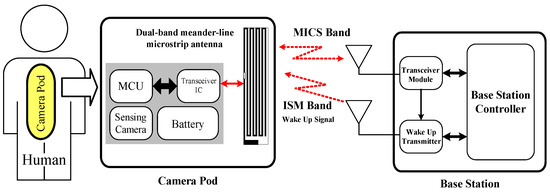
Figure 1.
The MICS/ISM meander-line microstrip antenna encapsulated in an oblong-shaped pod, together with the base station.
In the diagnosis, a patient orally ingests a pod which courses through the digestive tract and is excreted with the feces. The sensing camera captures images inside the gastrointestinal tract and the data are transmitted in real-time using the MICS band. Specifically, data are transmitted using the MICS band and the ISM bands are used to activate the pod from sleep mode. Sleep mode was incorporated to ensure efficient battery usage, since it usually takes 6 h after ingestion for food intake to reach the small intestine.
Figure 2 depicts the geometry of the proposed MICS/ISM meander-line microstrip antenna. A loading resistor, connecting the meander-line radiating patch with the flipped-L defected ground plane, was used to miniaturize the antenna. In [22,23,24,25], a microstrip antenna with a shorted pin connected to the ground plane was able to reduce the size of the antenna to a quarter-wavelength, and the shorted pin loading (resistor or capacitor) could further decrease the size to less than a quarter-wavelength due to the shift of the resonant frequency of the fundamental mode. The proposed antenna was implemented on a printed circuit board (PCB) with sheets of insulating material (substrate layer) and copper (metal layers) on the top and bottom sides. A PCB of Roger RO3210 substrate material was employed, which has a dielectric constant of 10.2, thickness of 1.27 mm (with copper cladding of 35 μm), surface resistivity of 103 MΩ, and loss tangent (tan δ) of 0.0027 [26]. The notations of the antenna parameters are defined in Table 2.
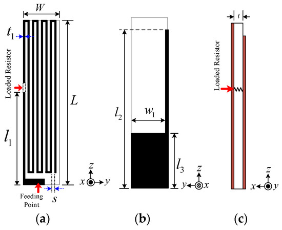
Figure 2.
Structure of the MICS/ISM meander-line microstrip antenna: (a) front view, (b) rear view, (c) side view.
Table 2.
Parameters of the proposed MICS/ISM meander-line microstrip antenna.
The antenna can achieve the impedance matching (|S11| ≤ −10 dB) at 400 MHz and 2.4 GHz with a quasi-omnidirectional radiation pattern. The first resonance-matching (MICS band) is attributable to the meander line and the second resonance (ISM bands) to the flipped-L defected ground plane. Since the pod with the MICS/ISM antenna encapsulated is intended for use inside the human body (i.e., a lossy material), simulations were carried out in different lossy-material environments: a pseudo-muscular cubicle, a multilayer spherical body-parts model, and a quasi-human body.
3. Results and Discussion
3.1. Simulation Results
The MICS/ISM microstrip antenna encapsulated in an oblong-shaped pod was simulated using CST microwave studio [27] in various lossy-material environments: a pseudo-muscular cubicle, a multilayer spherical body-parts model, and a quasi-human body.
Figure 3 depicts the MICS/ISM microstrip antenna encapsulated in a glass pod inside the pseudo-muscular cubicle (50 × 50 × 50 mm). There was air between the antenna and the container. Therefore, the material around the antenna and glass pod was investigated. The muscular cubicle was of lossy material with very high dielectric constants (57.12 and 52.72 for MICS and ISM, respectively). The simulation was carried out in the cubical model to ensure straightforwardness and time efficiency vis-à-vis the quasi-human body [12].
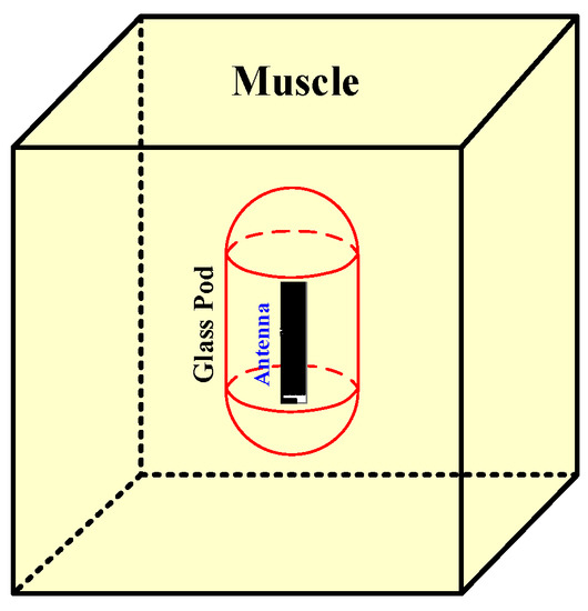
Figure 3.
The MICS/ISM meander-line microstrip antenna encapsulated in a glass pod inside the pseudo-muscular cubicle.
The simulation inside the muscular cubicle was performed to determine the initial physical size of the antenna, as shown in Table 2. The simulated impedance matching (|S11| ≤ −10 dB) was achieved at 400–406 MHz and at 2.41–2.47 GHz, as shown in Figure 4. Figure 5a,b respectively show the simulated xy- and yz-plane radiation patterns of the antenna in the muscular cubicle. The antenna gains at 403 MHz and 2.45 GHz (center frequency) were −36.04 dBi and −12.31 dBi, respectively. Moreover, the antenna gains along the operating frequency of the MICS/ISM meander-line microstrip antenna encapsulated in a glass pod inside the muscular cubicle are shown in Figure 6a,b.
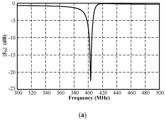
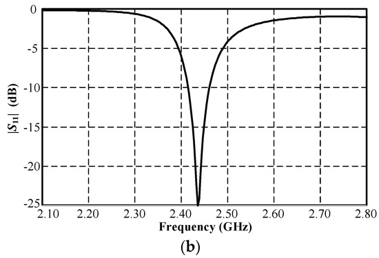
Figure 4.
Simulated |S11| of MICS/ISM meander-line microstrip antenna encapsulated in a glass pod inside the muscular cubicle: (a) MICS and (b) ISM bands.
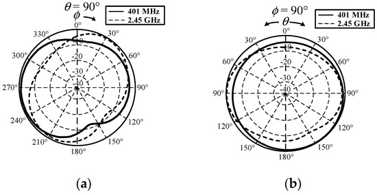
Figure 5.
Simulated radiation pattern of MICS/ISM meander-line microstrip antenna encapsulated in a glass pod inside the muscular cubicle: (a) xy and (b) yz planes.
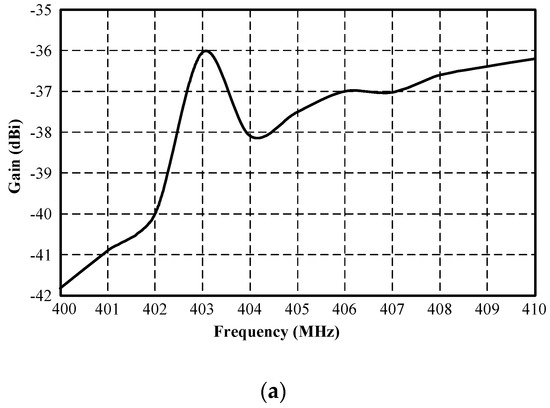
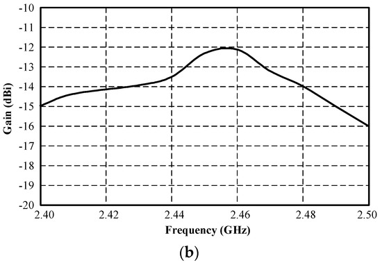
Figure 6.
Simulated gain of MICS/ISM meander-line microstrip antenna encapsulated in a glass pod inside the muscular cubicle: (a) MICS and (b) ISM bands.
Figure 7 depicts the lossy multilayer spherical body-parts model with the MICS/ISM microstrip antenna encapsulated in a glass pod at the innermost circle (area 1) [10,18]. In the simulation, the six layers of the lossy multilayer spherical body-parts model represented human internal organs and body parts with varying dielectric constants (Table 3) [28]: layer 1 was air, layer 2 was the glass pod, layer 3 was the stomach, layer 4 was the bone, layer 5 was the muscle, and layer 6 was free space. The dielectric constant plays a crucial role in the data-transmission performance of the antenna.
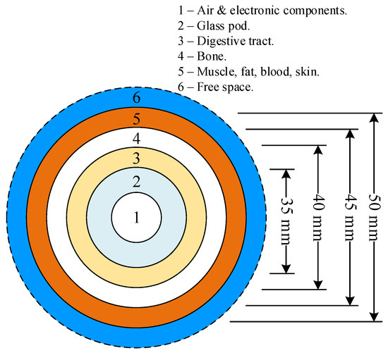
Figure 7.
The lossy multilayer spherical body-parts model with varying dielectric constants.
Table 3.
The conductivities and dielectric constants of human organs and body parts [28].
First of all, the lossy multilayer spherical body-parts model was considered as a single dielectric constant in a spherical model by varying the dielectric constants for each human organ and body part (Table 3). Figure 8 shows the simulated |S11| of the MICS/ISM meander-line microstrip antenna encapsulated in a glass pod inside the solid spherical model with a diameter of 50 mm, where the spherical model represented fat, bone, skin, muscle, blood, and the stomach, with varying dielectric constants. The result revealed that the |S11| varied with the dielectric constants of different layers of organs and body parts. The |S11| of the MICS band shifted to a higher frequency with an increase in the dielectric constant, while the dielectric constant had a negligible impact on the |S11| of the ISM bands. High conductivity had a minimal effect on the |S11| of the MICS band but negatively affected the impedance matching of the ISM band.
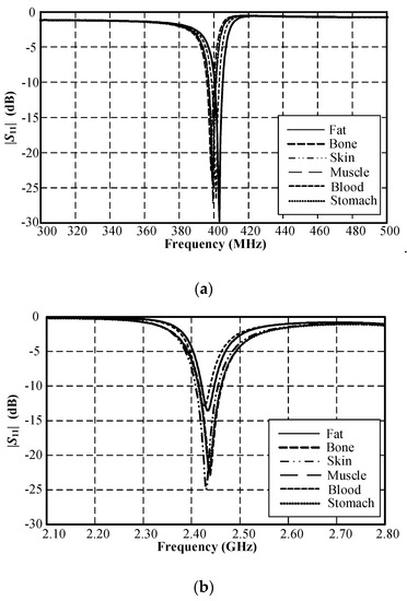
Figure 8.
Simulated |S11| of the MICS/ISM meander-line microstrip antenna encapsulated in a glass pod inside a solid spherical model with a diameter of 50 mm: (a) MICS and (b) ISM bands.
Figure 9 compares the simulated |S11| of the MICS/ISM microstrip antenna encapsulated in a glass pod inside the pseudo-muscular cubicle and in the multilayer spherical body-parts model. The results show the similarity between the |S11| of the antenna in the muscular cubicle and in multilayer spherical model, indicating the applicability of both models for the antenna simulation.
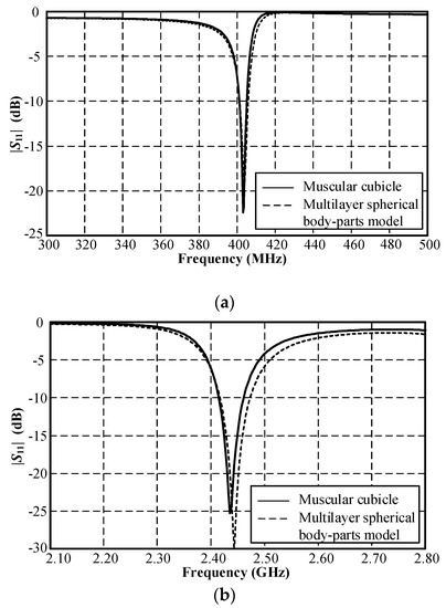
Figure 9.
Comparison between the simulated |S11| of the MICS/ISM meander-line microstrip antenna encapsulated in a glass pod inside the muscular cubicle and in the multilayer spherical body-parts model: (a) MICS and (b) ISM bands.
In addition, the geometry environment is also affected, which is estimated in Figure 10. Figure 10 depicts the quasi-human body model with the locations of the pod along the digestive tract from the throat through to the intestine. In Figure 11, the simulated |S11| of the MICS band shifts to a lower frequency as the pod courses along the gastrointestinal tract. However, the impedance-matching (|S11| ≤ −10 dB) falls inside the MICS band. On the other hand, the location of the pod had a negligible effect on the simulated |S11| of the ISM band. The physical size of the proposed meander-line microstrip antenna for the quasi-human body was optimized using a global optimization algorithm, namely the genetic algorithm (GA) in CST Microwave Studio [27]. Table 2 shows the optimal physical size of the meander-line microstrip antenna. Due to the high sensitivity of the antenna’s resonant frequency to the flipped-L defected ground plane (Figure 2), the ground-plane parameters (w1, l2, and l3) were optimized with the GA to achieve the resonant frequency at 403 MHz and 2.45 GHz. In the optimization, the GA parameters were as follows: population size, 10; maximum number of iterations, 30; uniform random distribution; mutation rate, 10%; random seed, 5. The GA converged after 10 iterations. The results were compared with the particle swarm optimization (PSO) algorithm in CST Microwave Studio. The comparison of the results from the GA and the PSO is shown in Table 4. These optimizations were employed to find two optimum solutions. The first solution was determined by adjusting the dimension of the antenna (total width and length; W × L) to achieve the maximum gain. It was obvious that the GA optimization could achieve maximum gains of −22 dBi at 403 MHz and −10.5 dBi at 2.45 GHz, respectively. The maximum gain from the PSO was −21 dBi at 403 MHz and −10 dBi at 2.45 GHz. However, the total sizes of the antenna with the maximum gains from the GA and particle swarm optimizations of 15 × 29 mm and 14 × 31 mm were too large to insert in the glass pod. The second solution was obtained by adjusting the dimensions of the antenna to get the minimum size that was appropriate for the glass pod. The minimum antenna size of 6 × 28 mm was obtained from both the GA and particle swarm optimizations. With this minimum size, the antenna gains from the GA and particle swarm optimizations were −36.04 dBi at 403 MHz and −12.31 dBi at 2.45 GHz, respectively. Moreover, the multi-objective GA and multi-objective PSO were also employed to find the solutions for both the maximum gain and minimum size. The gains were −24 dBi at 403 MHz and −11 dBi at 2.45 GHz for the multi-objective GA optimization and −23 dBi at 403 MHz and −11.5 dBi at 2.45 GHz for the multi-objective PSO. Nevertheless, the dimensions of the antenna from both the multi-objective GA and the multi-objective PSO algorithms of 14 × 29 mm and 15 × 29.5 mm were too large for the glass pod. From these optimization algorithms, it was found that the gain decreased with reductions in the antenna dimensions. Finally, the total size of the antenna was proposed to be 6 × 28 × 1.27 mm (W × L × H). This proposed antenna size is operable in the gastrointestinal tract with commercial OMOM capsules of 13 × 28 mm size [29]. It should be noted that the antenna size can be designed to fit with other smaller commercial capsules at the expense of maximum gain degradation. The proposed antenna can retain impedance matching for human tissue. It can also be robustly integrated with electronic components due to the antenna ground plane protection.
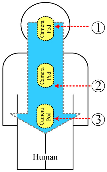
Figure 10.
The quasi-human body model with the locations of the pod along the digestive system, where 1, 2, and 3 denote the throat, stomach, and intestine.
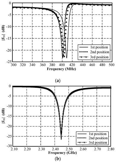
Figure 11.
Simulated |S11| of the MICS/ISM meander-line microstrip antenna along the digestive tract where the 1st, 2nd, and 3rd positions indicate the throat, stomach, and intestine: (a) MICS and (b) ISM bands.
Table 4.
Comparison of the optimization algorithms.
The specific absorption rates at the MICS and ISM bands were determined using CST Microwave Studio [27] with 1 mW input power. In the SAR analysis, the quasi-human body model was discretized into tissues of 1 g and 10 g in volume on average. According to the IEEE C95.1 international standard, the upper limits of the average SAR for the whole body are 0.08 W/kg (for action level) and 0.4 W/kg (for persons in controlled environments) [30]. The simulated maximum 1 g SARs were 0.000429 W/kg at 403 MHz and 0.026202 W/kg at 2.45 GHz. The corresponding 10 g SARs were 0.000209 W/kg at 403 MHz and 0.017021 W/kg at 2.45 GHz. The simulated SARs were substantially below the maximum limits of the international standard, indicating high safety for use inside the human body.
3.2. Experimental Results
Figure 12 depicts an antenna prototype fabricated using a Roger RO3210 printed circuit board with a dielectric constant of 10.2. Experiments were carried out with the prototype antenna encapsulated in a glass pod in free space (Figure 12c) and, subsequently, in equivalent liquid mixtures with dielectric constants resembling human tissue [31,32,33]. In the experiments, the equivalent liquid model was used in place of human participants, thereby rendering ethical approval unnecessary.
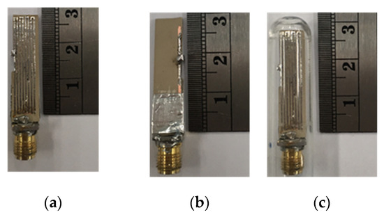
Figure 12.
Prototype of the MICS/ISM meander-line microstrip antenna: (a) front view, (b) rear view, (c) in the glass pod.
The equivalent liquid model was a mixture of three constituent parts: water, syrup, and salt. Syrup was used to vary the dielectric constant of the water and salt was used to increase the conductivity [31,32]. This method was chosen to obtain permittivity/conductivity relevant to the IEEE head and Federal Communications Commission (FCC) body tissue targets. In addition, the IEEE has provided the target values for head tissue-equivalent liquids in [34,35]. Table 5 lists nine experimental equivalent liquid mixtures obtained by varying syrup, salt, and water concentrations. A dielectric probe kit (N1501A, Keysight Technologies, Santa Rosa, CA, USA) was used to measure the dielectric constants and conductivities of the experimental mixtures, as shown Figure 13.
Table 5.
The concentrations of syrup, salt, and water in nine experimental mixtures of equivalent liquid.
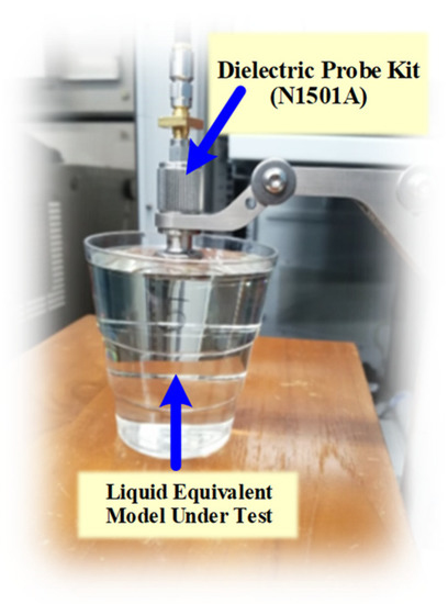
Figure 13.
Measurement of the dielectric constants of equivalent liquid using the N1501A dielectric probe kit.
Figure 14a,b respectively illustrate the real and imaginary parts of the dielectric constants of nine experimental equivalent liquid mixtures. In Figure 14a, mixture 1 (water) exhibits the highest dielectric constant, and the dielectric constant decreases with increases in the syrup concentration. Meanwhile, the conductivity can be seen to increase with increases in the salt concentration (Figure 14b) [32].
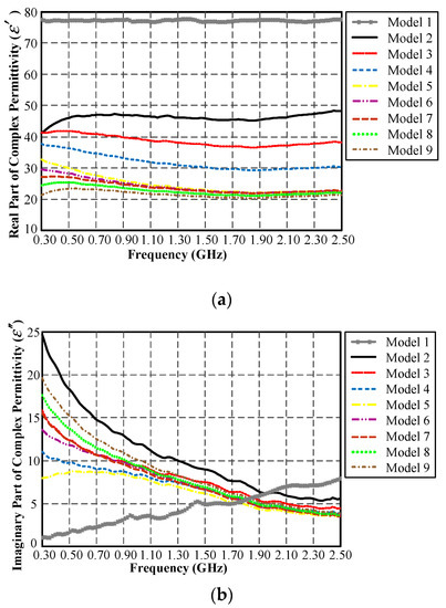
Figure 14.
The dielectric constants of nine experimental mixtures of equivalent liquid: (a) real part, (b) imaginary part.
Figure 15 compares the measured |S11| of the MICS/ISM meander-line microstrip antenna encapsulated in a glass pod in free space and in equivalent liquid mixtures 2 and 4 (Table 5). In these experiments we selected the equivalent liquid mixtures 2 and 4 because their dielectric constants closely resembled those of human body parts with dielectric constants between 30 and 48, as shown in Figure 14. Figure 16 depicts the measured xy- and yz-plane radiation patterns of the MICS/ISM meander-line antenna in equivalent liquid mixtures 2 and 4. The radiation has a quasi-omnidirectional pattern. The measured impedance bandwidths (|S11| ≤ −10 dB) for the MICS and ISM bands were 398–407 MHz and 2.41–2.48 GHz, with corresponding antenna gains of −38 dBi and −13 dBi.
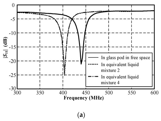
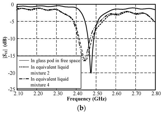
Figure 15.
Measured |S11| of the MICS/ISM meander-line microstrip antenna encapsulated in a glass pod in free space and in equivalent liquid mixtures 2 and 4: (a) MICS and (b) ISM bands.
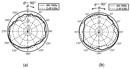
Figure 16.
Measured radiation patterns of MICS/ISM meander-line microstrip antenna in equivalent liquid mixtures 2 and 4: (a) xy and (b) yz planes.
Figure 17 depicts the SAR measurement setup in equivalent liquid mixtures using a 100 series EMC probe 100D model [36]. The probe reading (Pout) was converted into electric field strength using Equation (1) [36], where Pout is the output power from the probe (dBm), F is the operating frequency (MHz) (i.e., 403 MHz and 2450 MHz), and E is the electric field strength (V/m).
Figure 17.
SAR measurement setup in equivalent liquid mixtures with the antenna prototype encapsulated in a glass pod.
The distance between the MICS/ISM antenna prototype and the EMC probe had to be greater than , where a is the largest dimension of the prototype antenna. The SAR measurement was carried out in a continuous fashion for a total time of 6 min using the max-hold function in the spectrum analyzer (Fieldfox Handheld Spectrum Analyzer) and the maximum electric field strength (Emax) was determined. The specified averaging time of 6 min was an average of the time required for the maximum permissible values of the RF field strength or power density, following [34]. The SAR was then calculated using Equation (2) [34,35]:
where is the mass density in kg/m3, is the radian frequency, is the permittivity of free space (8.854 × 10⁻¹² F/m), is the imaginary part of the complex relative permittivity, is the conductivity in S/m, and Emax is the maximum electric field strength.
The measured SAR of equivalent liquid mixture 2 was 0.0054 W/kg at 403 MHz and 0.000587 W/kg at 2.45 GHz. For equivalent liquid mixture 4, the corresponding SARs were 0.0026 W/kg and 0.000421 W/kg. The measured SARs were substantially below the maximum safety limits of the IEEE C95.1 international standard, in which the upper limits of average SARs for the whole body are 0.08 W/kg (for action level) and 0.4 W/kg (for persons in controlled environments) [30].
4. Conclusions
This study proposed a MICS/ISM meander-line microstrip antenna encapsulated in an oblong-shaped pod for use in diagnoses of the gastrointestinal tract. The proposed microstrip antenna is operable in MICS and ISM bands and its structure consists of a meander-line radiating patch, a flipped-L defected ground plane, and a loading resistor to reduce the antenna’s total size. Simulations in a muscular cubicle and multilayer spherical model were carried out to determine the optimal physical size of the antenna. In a quasi-human body simulation, the impedance bandwidths (|S11| ≤ −10 dB) for the MICS and ISM bands were 400–406 MHz and 2.41–2.47 GHz, with respective antenna gains of −36.04 dBi and −12.31 dBi. The simulated radiation had a quasi-omnidirectional pattern. For verification, an antenna prototype was fabricated and experiments conducted in equivalent liquid mixtures with dielectric constants resembling those of human tissue. The measured impedance bandwidths (|S11| ≤ −10 dB) for the MICS and ISM bands were 398–407 MHz and 2.41–2.48 GHz. The corresponding antenna gains were −38 dBi and −13 dBi, with quasi-omnidirectional radiation patterns. The simulation and the measured results were thus in good agreement. The measured SARs were between 0.0026–0.0054 W/kg at 403 MHz and 0.000421–0.000587 W/kg at 2.45 GHz, which are substantially below the maximum safety limits of the IEEE C95.1 standard. The MICS/ISM microstrip antenna encapsulated in an oblong-shaped pod can potentially be used as an ingestible diagnostic tool for real-time gastrointestinal tract diagnosis.
Author Contributions
Conceptualization, S.K., A.B., and C.P.; methodology, S.K., A.B., and C.P.; investigation, S.K.; writing—original draft, S.K.; writing—review and editing, A.B. and C.P.; supervision, C.P.; funding acquisition, A.B. All authors have read and agreed to the published version of the manuscript.
Funding
This research was funded by the Office of the Higher Education Commission (OHEC) and the Thailand Research Fund (TRF), grant no. MRG6180089, and was funded by King Mongkut’s University of Technology North Bangkok, Contract No. KMUTNB-64-KNOW-45.
Institutional Review Board Statement
Not applicable.
Informed Consent Statement
Not applicable.
Data Availability Statement
The data used to support the findings of this study are available from the corresponding author upon request.
Conflicts of Interest
The authors declare no conflict of interest.
References
- Rosen, A.; Rosen, H.D. The role of engineering principles in the medical utilization of electromagnetic energies from kHz to visible light—Examples. J. Infrared Millim. Terahertz Waves 2009, 30, 1347–1386. [Google Scholar] [CrossRef]
- Rosen, A.; Stuchly, M.A.; Vorst, A.V. Applications of RF/microwaves in medicine. IEEE Trans. Microw. Theory Tech. 2002, 50, 963–974. [Google Scholar] [CrossRef]
- Ishida, T.; Inoue, T.; Inoue, T.; Endo, T.; Fujimura, M.; Niizuma, K.; Endo, H.; Tominaga, T. Brain temperature measured by magnetic resonance spectroscopy to predict clinical outcome in patients with infarction. Sensors 2021, 21, 490. [Google Scholar] [CrossRef] [PubMed]
- Lee, Y.Y.B.; Huang, Y.; El-Deredy, W.; Lisboa, P.J.G.; Arus, C.; Harris, P. Robust methodology for the discrimination of brain tumours from in-vivo magnetic resonance spectra. IEE Proc. Sci. Meas. Technol. 2000, 147, 309–314. [Google Scholar] [CrossRef]
- Nelson, B.D.; Karipott, S.S.; Wang, Y.; Ong, K.G. Wireless technologies for implantable devices. Sensors 2020, 20, 4604. [Google Scholar] [CrossRef] [PubMed]
- Mahfouz, M.R.; To, G.; Kuhn, M.J. Smart instruments: Wireless technology invades the operating room. In Proceedings of the IEEE Topical Conference on Biomedical Wireless Technologies, Networks, and Sensing Systems (BioWireleSS), Santa Clara, CA, USA, 15–18 January 2012; pp. 33–36. [Google Scholar]
- Islama, M.N.; Yuce, M.R. Review of Medical Implant Communication System (MICS) band and network. ICT Express 2016, 2, 188–194. [Google Scholar] [CrossRef]
- Shobha, G.; Chittal, R.R.; Kumar, K. Medical applications of wireless networks. In Proceedings of the Second International Conference on Systems and Networks Communications (ICSNC 2007), Cap Esterel, France, 25–31 August 2007; pp. 1–6. [Google Scholar]
- Ghamari, M.; Janko, B.; Sherratt, R.S.; Harwin, W.; Piechockic, R.; Soltanpur, C. A survey on wireless body area networks for eHealthcare systems in residential environments. Sensors 2016, 16, 831. [Google Scholar] [CrossRef] [PubMed]
- Damaj, A.; el Misilmani, H.M.; Chahine, S.A. Implantable antennas for biomedical applications: An overview on alternative antenna design methods and challenges. In Proceedings of the International Conference on High Performance Computing & Simulation (HPCS), Orleans, France, 16–20 July 2018; pp. 31–37. [Google Scholar]
- Abadia, J.; Merli, F.; Zurcher, J.-F.; Mosig, J.R.; Skriverviki, A.K. 3D-spiral small antenna design and realization for biomedical telemetry in the MICS band. Radioengineering 2009, 18, 359–367. [Google Scholar]
- Scarpello, M.L.; Kurup, D.; Rogier, H.; Ginste, D.V.; Axisa, F.; Vanfleteren, J.; Joseph, W.; Martens, L.; Vermeeren, G. Design of an implantable slot dipole conformal flexible antenna for biomedical applications. IEEE Trans. Antennas Propag. 2011, 59, 3556–3564. [Google Scholar] [CrossRef]
- Lee, C.-M.; Yo, T.-C.; Huang, F.-J.; Luo, C.-H. Bandwidth enhancement of planar inverted-F antenna for implantable biotelemetry. Microw. Opt. Technol. Lett. 2009, 51, 749–752. [Google Scholar] [CrossRef]
- Lee, C.-M.; Yo, T.-C.; Luo, C.-H.; Tu, C.-H.; Juang, Y.-Z. Compact broadband stacked implantable antenna for biotelemetry with medical devices. Electron. Lett. 2007, 43, 660–662. [Google Scholar] [CrossRef]
- Kumar, S.A.; Shanmuganantham, T. Implantable CPW fed dual folded dipole antenna for biomedical applications. In Proceedings of the International Conference on Computing, Communication and Networking Technologies, Coimbatore, India, 26–28 July 2012; pp. 1–5. [Google Scholar]
- Palandoken, M. Compact bioimplantable MICS and ISM band antenna design for wireless biotelemetry applications. Radioengineering 2017, 26, 917–923. [Google Scholar] [CrossRef]
- Farhad, G.; Mohan, A.S. Miniaturized slot PIFA antenna for tripleband implantable biomedical applications. In Proceedings of the IEEE MTT-S International Microwave Workshop Series on RF and Wireless Technologies for Biomedical and Healthcare Applications (IMWS-BIO), Singapore, 9–11 December 2013; pp. 1–3. [Google Scholar]
- Chrissoulidis, D.P.; Laheurte, J.-M. Radiation from an encapsulated hertz dipole implanted in a human torso model. IEEE Trans. Antennas Propag. 2016, 64, 4984–4992. [Google Scholar] [CrossRef]
- Nikolayev, D.; Zhadobov, M.; le Coq, L.; Karban, P.; Sauleau, R. Robust ultraminiature capsule antenna for ingestible and implantable applications. IEEE Trans. Antennas Propag. 2017, 65, 6107–6119. [Google Scholar] [CrossRef]
- Nikolayev, D. Modeling and characterization of in-body antennas. In Proceedings of the 2018 IEEE 17th International Conference on Mathematical Methods in Electromagnetic Theory (MMET), Kyiv, Ukraine, 2–5 July 2018; pp. 1–5. [Google Scholar]
- Fernández, M.; Thiel, D.V.; Arrinda, A.; Espinosa, H.G. An inward directed antenna for gastro-intestinal radio pill tracking at 2.45 GHz. Microw. Opt. Technol. Lett. 2018, 60, 1644–1649. [Google Scholar] [CrossRef]
- Wong, K.-L. Compact and Broadband Microstrip Antennas; John Wiley & Sons: Hoboken, NJ, USA, 2002. [Google Scholar]
- Lu, J.-H.; Yang, K.-P. Slot-coupled compact triangular microstrip antenna with lumped load. In Proceedings of the IEEE Antennas and Propagation Society International Symposium, Atlanta, GA, USA, 21–26 June 1998; pp. 916–919. [Google Scholar]
- Chen, H.-T. Compact circular microstrip antenna with embedded chip resistor and capacitor. In Proceedings of the IEEE Antennas and Propagation Society International Symposium, Atlanta, GA, USA, 21–26 June 1998; pp. 1356–1359. [Google Scholar]
- Wong, K.-L.; Chen, W.-S. Compact microstrip antenna with dual-frequency operation. Electron. Lett. 1997, 33, 646–647. [Google Scholar] [CrossRef]
- RO3210 TM Circuit Materials High Frequency Circuit Laminates; Rogers Corporation: Chandler, AZ, USA; Available online: www.rogerscorp.com (accessed on 20 August 2018).
- CST Studio Suite 3D EM Simulation and Analysis Software, Studio, C.P. CST Studio Suite; Simulia: Darmstadt, Germany, 2010.
- Italian National Research Council Institute for Applied Physics. Dielectric Properties of Body Tissues in the Frequency Range 10 Hz–100 GHz. Available online: http://niremf.ifac.cnr.it/ (accessed on 18 September 2018).
- Yuce, M.R.; Dissanayake, T. Easy-to-swallow wireless telemetry. IEEE Microw. Mag. 2012, 13, 90–101. [Google Scholar] [CrossRef]
- Institute of Electrical and Electronics Engineers (IEEE). Safety Levels with Respect to Human Exposure to Radio Frequency Electromagnetic Fields 3 kHz to 300 GHz; IEEE Std. C95.1; Institute of Electrical and Electronics Engineers (IEEE): Piscataway, NJ, USA, 2019. [Google Scholar]
- Kanda, M.Y.; Ballen, M.; Salins, S.; Chou, C.-K.; Balzano, Q. Formulation and characterization of tissue equivalent liquids used for RF densitometry and dosimetry measurements. IEEE Trans. Microw. Theory Tech. 2004, 52, 2046–2056. [Google Scholar] [CrossRef]
- Sorgucu, U.; Develi, I. Head equivalent liquids: A review on composing, recipes and standards. In Proceedings of the World Congress on Electrical Engineering and Computer Systems and Science, Budapest, Hungary, 16–17 August 2016; pp. 1–6. [Google Scholar]
- Simunic, D.; Saik, D. Preparation of head tissue equivalent simulating liquid at mobile communications frequencies. In Proceedings of the IEEE International Symposium on Electromagnetic Compatibility, Istanbul, Turkey, 11–16 May 2003; pp. 1237–1240. [Google Scholar]
- Institute of Electrical and Electronics Engineers (IEEE). Practice for Measurements and Computations of Radio Frequency Electromagnetic Fields with Respect to Human Exposure to Such Fields, 100 kHz–300 GHz; IEEE Std. C95.3; Institute of Electrical and Electronics Engineers (IEEE): Piscataway, NJ, USA, 2002. [Google Scholar]
- Institute of Electrical and Electronics Engineers (IEEE). Practice for Determining the Peak Spatial-Average Specific Absorption Rate (SAR) in the Human Body Due to Wireless Communications Devices: Experimental Techniques; IEEE Std. 1528; Institute of Electrical and Electronics Engineers (IEEE): Piscataway, NJ, USA, 2003. [Google Scholar]
- Beehive Electronics. 100 Series EMC Probes; Beehive Electronics: Sebastopol, CA, USA, 2005. [Google Scholar]


Publisher’s Note: MDPI stays neutral with regard to jurisdictional claims in published maps and institutional affiliations. |
© 2021 by the authors. Licensee MDPI, Basel, Switzerland. This article is an open access article distributed under the terms and conditions of the Creative Commons Attribution (CC BY) license (https://creativecommons.org/licenses/by/4.0/).