Design of a Novel Six-Axis Wrist Force Sensor

Abstract
1. Introduction
2. Structural Design Ideas of a Novel Six-Axis Wrist Force Sensor
2.1. Wrist Force Sensor with Floating Beams
2.2. Design Ideas of the Novel Six-Axis Wrist Force Sensor
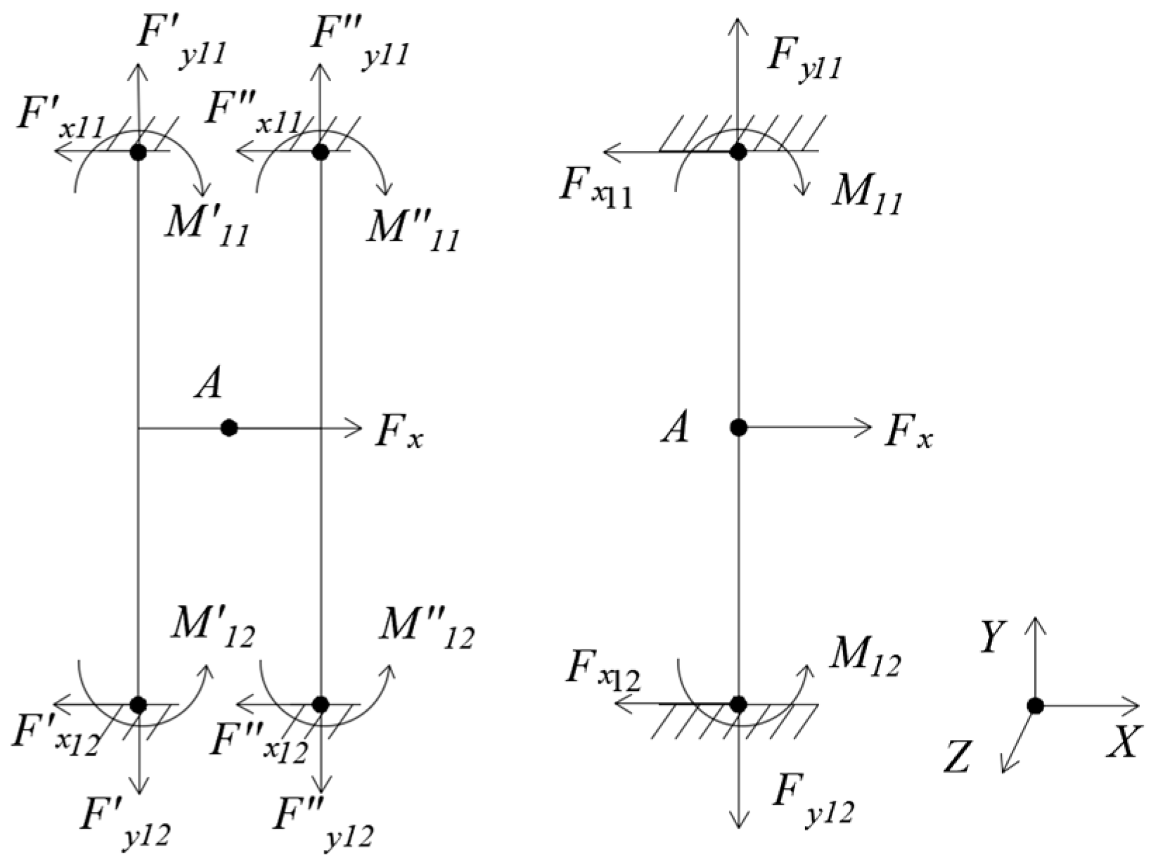
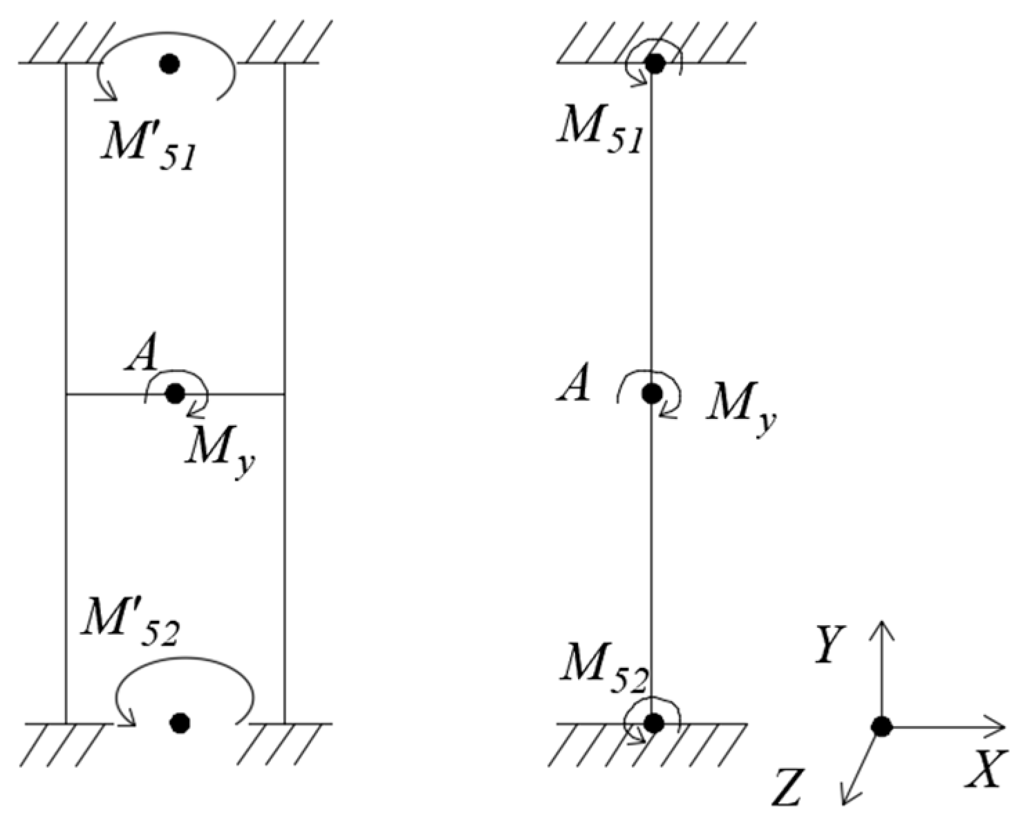
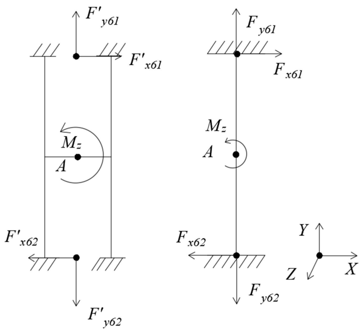
3. Mechanics Analysis
3.1. Comparison between H-Beam and Floating Beam
3.2. Comparison between Single Beam and Parallel Beam
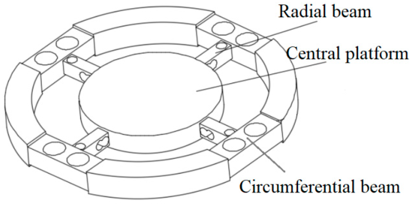
4. Design of a Novel Six-Axis Wrist Sensor
5. Strain Gauges Position and Connection Principles of Circuits
5.1. Simulation of the Novel Sensor
5.1.1. Simulation Modeling
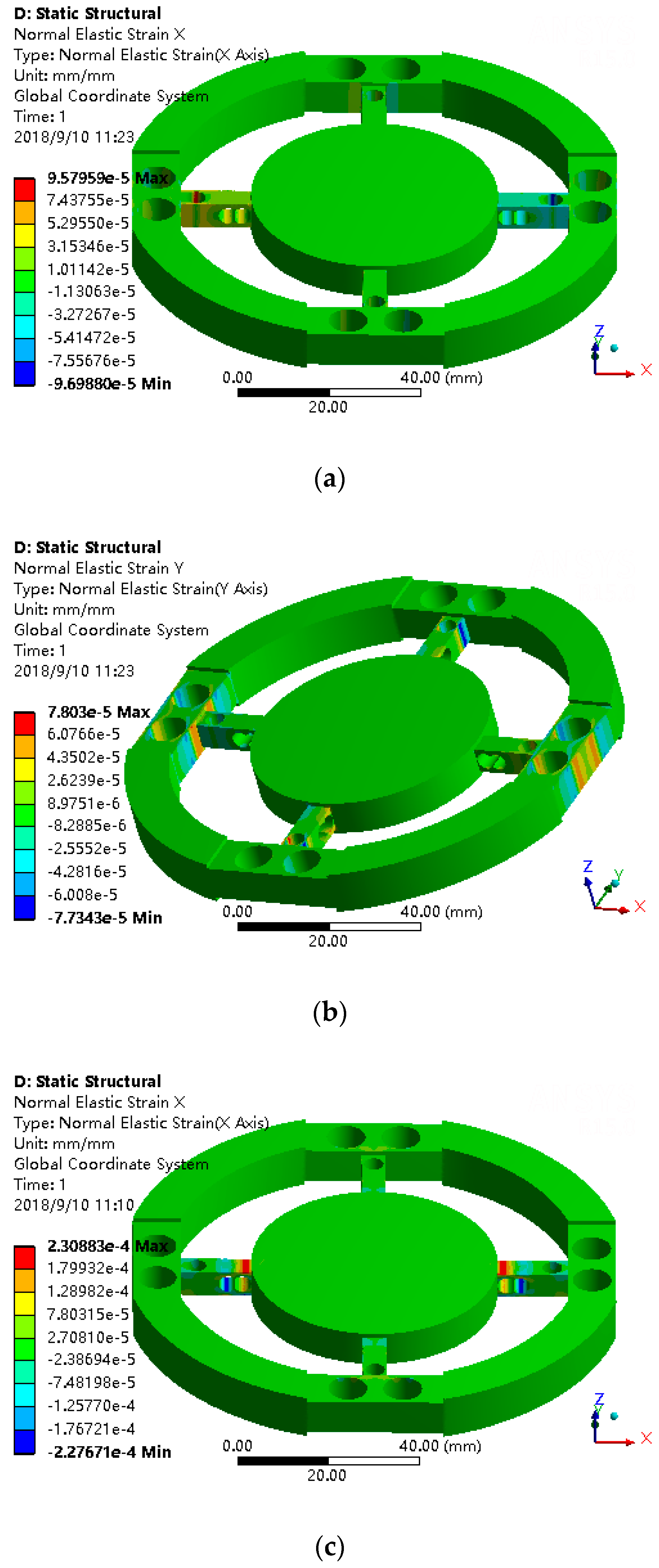
5.1.2. Simulation Result
5.2. Strain Gauge Position and Connection Principles of Full-Bridge Circuits
6. Example
7. Conclusions
- (1)
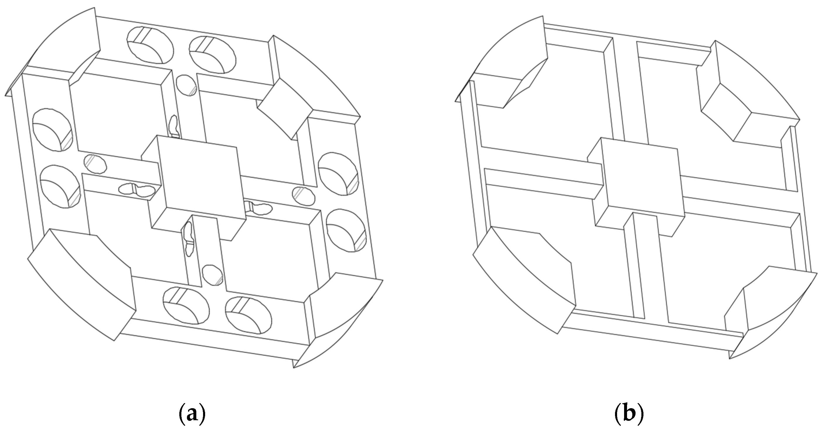
- This article designs a novel elastomer structure of six-axis wrist force sensor based on the structure of the original six-axis wrist force sensor with cross-beams and floating beams, and described the design ideas in detail. Including changing the floating beams to the H-beams to improve the dynamic performance of sensor and punching holes in beams and using parallel beams structures to increase sensitivity of sensor. In the process of design, the advantages of the structures were analyzed and compared by mechanical modeling and were verified by finite element analysis.
- (2)
- In the process of static simulation analysis, we observe the influence rule of the strain distribution of the novel sensor elastomer under loading various forces and torques, and sum up the best positions where strain gauges are pasted and the connection modes of full-bridge circuits which can achieve decoupling in theory.
- (3)
- After static and dynamic simulation analysis of the two sensor elastomers, the results show that the novel sensor is superior to the original six-axis wrist force sensor with cross-beams and floating beams on both static and dynamic performance, especially on the dynamic performance. The performance of the sensor is improved, which is the base and precondition of the control of the robot with high speed and high precision
- (4)
- The optimization design of this novel six-axis wrist force sensor elastomer should be done, which can further improve its performance to meet the requirements of high-speed and high-precision operation robots.
Author Contributions
Funding
Acknowledgments
Conflicts of Interest
References
- Ahola, J.M.; Seppälä, T.; Koskinen, J.; Heikkilä, T. Calibration of the pose parameters between coupled 6-axis F/T sensors in robotics applications. Robot. Auton. Syst. 2017, 89, 1–8. [Google Scholar] [CrossRef]
- Gafforda, J.; Doshi-Veleza, F.; Wooda, R.; Walsh, C. Machine learning approaches to environmental disturbance rejection in multi-axis optoelectronic force sensors. Sens. Actuators A Phys. 2016, 248, 78–87. [Google Scholar] [CrossRef]
- Zhao, Y.; Zhang, C.; Zhang, D.; Shi, Z.; Zhao, T. Mathematical Model and Calibration Experiment of a Large Measurement Range Flexible Joints 6-UPUR Six-Axis Force Sensor. Sensors 2016, 16, 1271. [Google Scholar] [CrossRef] [PubMed]
- Liang, Q.K.; Zhang, D.; Coppola, G.; Wu, W.N.; Zou, K.L.; Wang, Y.N.; Sun, W.; Ge, Y.J.; Ge, Y. Modular design and development methodology for robotic multi-axis F/M sensors. Sci. Rep. 2016, 6, 1–8. [Google Scholar] [CrossRef] [PubMed]
- Watson, P.C.; Drake, S.H. Pedestal and wrist force sensors for automatic assembly. In Proceedings of the 5th International Symposium on Industrial Robots, Chicago, IL, USA, 22–24 September 1975; pp. 501–511. [Google Scholar]
- Uchiyama, M.; Bayo, E.; Palma-Villalon, E. A systematic design procedure to minimize a performance index for robot force sensors. J. Dyn. Syst. Meas. Control 1991, 113, 388–394. [Google Scholar] [CrossRef]
- Kim, G.S. Design of a six-axis wrist force/moment sensor using FEM and its fabrication for an intelligent robot. Sens. Actuators A Phys. 2007, 133, 27–34. [Google Scholar] [CrossRef]
- Ma, J.; Song, A. Fast Estimation of Strains for Cross-Beams Six-Axis Force/Torque Sensors by Mechanical Modeling. Sensors 2013, 13, 6669–6686. [Google Scholar] [CrossRef] [PubMed]
- Yoshikawa, T.; Miyazaki, T. A six-axis of force sensor with three-dimensional cross-shape structure. In Proceedings of the 1989 International Conference on Robotics and Automation, Scottsdale, AZ, USA, 14–19 May 1989; pp. S249–S255. [Google Scholar]
- Wu, B.; Cai, P. Decoupling analysis of a sliding structure six-axis force/torque sensor. Meas. Sci. Rev. 2013, 13, 187–193. [Google Scholar] [CrossRef]
- Yuan, C.; Luo, L.P.; Yuan, Q.; Wu, J.; Yan, R.J.; Kim, H.; Shin, K.S.; Han, C.S. Development and evaluation of a compact 6-axis force/moment sensor with a serial structure for the humanoid robot foot. Measurement 2015, 70, 110–122. [Google Scholar] [CrossRef]
- Kübler, B.; Seibold, U.; Hirzinger, G. Development of actuated and sensor integrated forceps for minimally invasive robotic surger. Int. J. Med. Robot. Comput. Assist. Surg. 2005, 1, 96–107. [Google Scholar] [CrossRef] [PubMed]
- Jia, Z.Y.; Lin, S.; Liu, W. Measurement method of six-axis load sharing based on the Stewart platform. Measurement 2010, 43, 329–335. [Google Scholar] [CrossRef]
- Draisey, S. Multi-axes static/dynamic force sensor. In Proceedings of the NGST Science and Technology Exposition, Hyannis, MA, USA, 13–16 September 1999; pp. 1–12. [Google Scholar]
- Schott, J. Tactile sensor with decentralized signal conditioning. In Proceedings of the 9th IMEKO World Congress, Beilin, Germany, 24–28 May 1982; Volume 7, pp. 138–143. [Google Scholar]
- Chen, D.; Song, A.; Li, A. Six-axis force torque sensor with large measurement range used for the space manipulator. Procedia Eng. 2015, 99, 1164–1170. [Google Scholar] [CrossRef]
- Wang, Y.; Zuo, G.; Chen, X.; Liu, L. Strain Analysis of Six-Axis Force/Torque Sensors Based on Analytical Method. IEEE Sens. J. 2017, 17, 4394–4404. [Google Scholar] [CrossRef]
- Kang, M.K.; Lee, S.; Kim, J.H. Shape optimization of a mechanically decoupled six-axis force/torque sensor. Sens. Actuators A 2014, 209, 41–51. [Google Scholar] [CrossRef]
- Sun, Y.; Liu, Y.; Zou, T.; Jin, M.; Liu, H. Design and optimization of a novel six-axis force/torque sensor for space robot. Measurement 2015, 65, 135–148. [Google Scholar] [CrossRef]
- Liu, Z.S.; Lu, Y.M.; Chen, E.W.; Wang, Y. Structure design for the elastic body of a six-axis wrist force sensor. In Proceedings of the 3rd International Conference on Design Engineering and Science, Pilsen, Czech Republic, 31 August–3 September 2014. [Google Scholar]
- Wang, Y.; Hu, S.; Zhang, S.; Lu, Y.; Liu, Z. A Six-Axis Force Sensor Elastic Body. CN106768522-A, 31 May 2017. [Google Scholar]
- Yang, B. Mechanics of Materials; China Machine Press: Beijing, China, 2002. [Google Scholar]
- Liu, J. Mechanical Characteristics of Parallel Beam Type Weighing Sensor. Sci. Technol. Appl. 2009, 38, 1–7. [Google Scholar]
- Xu, Z. A Brief Tutorial on Elastic Mechanics; Higher Education Press: Beijing, China, 2002. [Google Scholar]


| Fx = 50 N | Fy = 50 N | Fz = 50 N | Mx = 2.5 Nm | My = 2.5 Nm | Mz = 2.5 Nm | |
|---|---|---|---|---|---|---|
| H-beam | yx = 3.8 × 10⁻² mm | yy = 2.5 × 10⁻⁴ mm | yz = 2.5 × 10⁻³ mm | θx = 1.2 × 10⁻³ | θy = 4.8 × 10⁻³ | θz = 7.6 × 10⁻⁴ |
| Floating beam | yx = 7.3 × 10⁻² mm | yy = 5.1 × 10⁻⁴ mm | yz = 4.9 × 10⁻³ mm | θx = 2.2 × 10⁻³ | θy = 8.5 × 10⁻² | θz = 2.5 × 10⁻² |
| Length × Width × Height (mm) | Minimum Thickness Beside the Hole (mm) | Diameter × Height (mm) | |
|---|---|---|---|
| Circumferential beam | 30 × 10.489 × 8 | t1 = 0.9945 | |
| Radical beam | 16 × 5.3 × 6 | t2 = 0.5, t3 = 1, t4 = 1 | |
| Central platform | 54 × 6 |
| R11 | R12 | R13 | R14 | R21 | R22 | R23 | R24 | R31 | R32 | R33 | R34 | R61 | R62 | R63 | R64 | |
|---|---|---|---|---|---|---|---|---|---|---|---|---|---|---|---|---|
| Fx | + | + | − | − | + | + | − | − | 0 | 0 | 0 | 0 | + | + | − | − |
| Fy | 0 | 0 | 0 | 0 | 0 | 0 | 0 | 0 | + | + | − | − | − | + | − | + |
| Fz | + | − | + | − | − | + | − | + | − | + | − | + | 0 | 0 | 0 | 0 |
| Mx | 0 | 0 | 0 | 0 | 0 | 0 | 0 | 0 | − | + | + | − | 0 | 0 | 0 | 0 |
| My | + | − | − | + | − | + | + | − | 0 | 0 | 0 | 0 | 0 | 0 | 0 | 0 |
| Mz | 0 | 0 | 0 | 0 | 0 | 0 | 0 | 0 | 0 | 0 | 0 | 0 | − | + | + | − |
| R41 | R41′ | R42 | R42′ | R43 | R43′ | R44 | R44′ | R51 | R51′ | R52 | R52′ | R53 | R53′ | R54 | R54′ | |
| Fx | + | + | − | − | − | − | + | + | + | − | − | + | − | + | + | − |
| Fy | − | + | + | − | + | − | − | + | + | + | − | − | − | − | + | + |
| Fz | + | + | − | − | + | + | − | − | + | + | − | − | + | + | − | − |
| Mx | 0 | 0 | 0 | 0 | 0 | 0 | 0 | 0 | + | + | − | − | + | + | − | − |
| My | + | + | − | − | + | + | − | − | 0 | 0 | 0 | 0 | 0 | 0 | 0 | 0 |
| Mz | + | − | − | + | + | − | − | + | + | − | − | + | + | − | − | + |
| Main Beam Width × Height (mm) | Floating Beam Length × Width × Height (mm) | Central Platform Length × Width × Height (mm) | External Diameter (mm) | ||
|---|---|---|---|---|---|
| Sensor 1 | 5 × 5 | 15.5 × 1 × 5 | 16 × 16 × 7 | 76 | |
| Radial Beam Width × Height (mm) | Circumferential Beam Length × Width × Height (mm) | Central Platform Length × Width × Height (mm) | External Diameter (mm) | The Minimum Thickness Beside the Hole (mm) | |
| Sensor 2 | 5 × 5 | 15.5 × 9.4 × 5 | 16 × 16 × 7 | 76 | t1 = 0.8, t2 = 0.5, t3 = 0.75, t4 = 0.75 |
| Fx = 100 N | Fz = 100 N | Mx = 3 N·m | Mz = 3 N·m | |
|---|---|---|---|---|
| Sensor 1 | 2.18 × 10⁻³ | 1.48 × 10⁻³ | 2.37 × 10⁻³ | 1.34 × 10⁻³ |
| Sensor 2 | 2.25 × 10⁻³ | 2.78 × 10⁻³ | 2.26 × 10⁻³ | 2.38 × 10⁻³ |
| Characteristic of Vibration | Translation along X-axis | Translation along Y-axis | Translation along Z-axis | Rotation around X-axis | Rotation around Y-axis | Rotation around Z-axis |
|---|---|---|---|---|---|---|
| Frequency of sensor 1 (Hz) | 1934.2 | 1934.3 | 2325.6 | 6913.8 | 6913.6 | 9075.5 |
| Frequency of sensor 2 (Hz) | 5910.9 | 5911.1 | 3742.5 | 11185.0 | 11,185.0 | 11,107.0 |
© 2018 by the authors. Licensee MDPI, Basel, Switzerland. This article is an open access article distributed under the terms and conditions of the Creative Commons Attribution (CC BY) license (http://creativecommons.org/licenses/by/4.0/).
Share and Cite
Hu, S.; Wang, H.; Wang, Y.; Liu, Z. Design of a Novel Six-Axis Wrist Force Sensor. Sensors 2018, 18, 3120. https://doi.org/10.3390/s18093120
Hu S, Wang H, Wang Y, Liu Z. Design of a Novel Six-Axis Wrist Force Sensor. Sensors. 2018; 18(9):3120. https://doi.org/10.3390/s18093120
Chicago/Turabian StyleHu, Shanshan, Huaiyang Wang, Yong Wang, and Zhengshi Liu. 2018. "Design of a Novel Six-Axis Wrist Force Sensor" Sensors 18, no. 9: 3120. https://doi.org/10.3390/s18093120
APA StyleHu, S., Wang, H., Wang, Y., & Liu, Z. (2018). Design of a Novel Six-Axis Wrist Force Sensor. Sensors, 18(9), 3120. https://doi.org/10.3390/s18093120