Abstract
Titanium dioxide (TiO2) coatings have a wide range of applications. Anatase exhibits hydrophilic, antimicrobial, and photocatalytic properties for the degradation of organic pollutants or water splitting. The main challenge is to obtain durable anatase nanoparticle coatings on plastic substrates by using straightforward approaches. In the present study, we revealed the preparation of a transparent TiO2 coating on polymethylmethacrylate (PMMA), widely used for organic optical fibres as well as other polymer substrates such as polypropylene (PP), polystyrene (PS), and polycarbonate (PC). The films were spin-coated at room temperature without annealing; therefore, our approach can be used for thermo-sensitive substrates. The deposition was successful due to the use of stripped ultra-small (<4 nm) TiO2 particles. Coatings were studied for the photocatalytic degradation of organic pollutants such as MB, methyl orange (MO), and rhodamine B (RB) under UV light. The TiO2 coating on PMMA degraded over 80% of RB in 300 min under a 365 nm, 100 W mercury lamp, showing a degradation rate constant of 6 × 10⁻³ min−1. The coatings were stable and showed no significant decrease in degradation activity even after five cycles.
1. Introduction
TiO2 is well-known to exhibit photocatalytic properties for application in antibacterial [1] and self-cleaning surfaces [2], degradation of organic pollution [3], or water splitting [4]. The TiO2 coatings have been produced by different methods such as chemical vapour deposition (CVD) [5], dip-coating [6] and ultrasonic spray pyrolysis [7]. All of these approaches in most cases require annealing; thus, the substrates are limited to brittle inorganics. Organic substrates are more desired because they are flexible and thus can be applied to a wider range of applications.
TiO2 coatings on organic substrates have been realised by Nagasawa et al. [8], Shahmohammadi et al. [9], and Phuinthiang et al. [10]. Nagasawa et al. deposited a coating on a PMMA polymer by using atmospheric-pressure plasma-enhanced chemical vapour deposition (AP-PECVD). By using this method, Nagasawa et al. were able to produce UV-shielding TiO2 coatings with a decrease in UV light absorption by 99% in the 200–280 nm range and with a visible light transmittance above 95%. Although the produced coatings showed good light transmittance properties, the used method requires specific equipment and cannot be used for large surface area samples. Scanning electron microscope (SEM) images for the produced coatings showed a large agglomerate presence (larger than 300 nm) [8].
Shahmohammadi et al. used the low-temperature atomic layer deposition (ALD) method to produce a TiO2 coating on PMMA for use in biomedical systems. The produced coatings increased the wettability and nanohardness of the PMMA substrate but no significant changes in surface roughness were observed. The produced TiO2 nanocoating was able to protect the PMMA surface against thermal and brushing tests, maintaining surface integrity and wettability. The TiO2 film reduced the initial fungal adhesion, which can lead to the use of PMMA in biomedical applications. However, ALD is associated with high production costs and slow manufacturing speeds; in this case, to obtain a 50–80 nm thick coating, cycles must be repeated 50 times, which takes approx. 30 min [9].
Phuinthiang et al. studied the TiO2 coating on the polyvinylchloride (PVC) substrate. They used sol–gel and photon assistance to avoid thermal processes in thin film crystallisation. As stated in their work, they managed to obtain high-quality samples at room temperature. Produced samples showed high photocatalytic activity based on the bacteria viability assay. Phuinthiang et al. managed to produce a high-quality, low-cost coating that is easily manufacturable. Although the produced samples showed high photocatalytic activity, there are no studies regarding the repeatability of these coatings and their endurance [10].
We hypothesise that the transparent, durable, and photocatalytically active TiO2 coatings can be obtained from stripped ultra-small nanoparticles in a single step at room temperature. The PMMA substrate has been chosen because this polymer can be used to produce flexible optical fibres for photocatalysis reactors [11]. PMMA are flexible and cheaper than brittle quartz optical fibres.
2. Results
The performed synthesis method yielded ultra-small anatase TiO2 nanoparticles, as indicated by X-ray diffraction (XRD), Raman, and transmission electron microscopy (TEM) studies. The TEM images in Figure 1a revealed single-crystalline particles with the mean particle size of 3.90 nm and a particle size distribution of 0.17 nm. The anatase structure was confirmed by XRD diffractogram (Figure 1c) and the Raman spectra (Figure 1d). Both methods did not show any indication of impurity phases. In accordance with XRD, the particles consisted of an anatase phase (JCPDS 21 1272). The Raman spectra in Figure 1d showed peaks at 148.17 cm−1 (Eg), 198.34 cm−1 (Eg), 398.13 cm−1 (B1g), 515.36 cm−1 (A1g), and 6638.85 cm−1 (Eg), which corresponded to the anatase TiO2 vibrational modes [12,13]. When compared to the literature, the Raman spectra had a slight Raman band shift due to the deformation of the scattering paths caused by the small size of the particles (Figure 1d) [14,15].
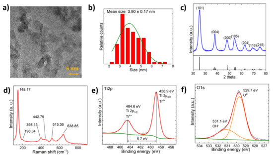
Figure 1.
(a) TEM micrograph of the synthesised nanoparticles at 450,000× magnification. (b) Size distribution histogram for synthesised nanoparticles. (c) XRD diffractogram with JCPDS 21-1272 XRD data. (d) Raman spectra of TiO2 nanoparticles. (e) High-resolution XPS of the Ti 2p peak with peak fitting. (f) High-resolution XPS of the O 1s peak with peak fitting.
The X-ray photoelectron spectroscopy (XPS) spectra of Ti 2p and O 1s are demonstrated in Figure 1e,f, respectively. The binding energy of the Ti 2p3/2 peak at 458.9 eV only indicates the Ti4+ oxidation state without shoulder peaks related to Ti3+. Peak splitting between Ti 2p3/2 and Ti 2p1/2 peaks was 5.7 eV, which corresponds to the literature values for anatase [16]. Oxide lattice oxygen component was found as a majority of the signal with a binding energy of 529.7 eV, while a ~26 (±1) % –OH surface hydroxyl component was present at ~531.1 eV binding energy. The signal can be interpreted as the first couple of monolayers of surface hydroxyl [17]. Band gap energy according to diffuse reflectance spectroscopy (DRS) was determined using the Tauc plot to be ~3.13 eV (Figure S1).
The synthesised TiO2 nanoparticles showed high photocatalytic activity. The activity for photocatalytic MB degradation (5 ppm in water) was tested for the synthesised TiO2 nanoparticle powders and compared with commercial Aeroxide ®® P25. Figure 2a shows the MB degradation efficiency (%) for the synthesised and commercial TiO2. The synthesised TiO2 degraded around 55% MB already in 10 min, while commercial TiO2 can degrade only 10% at the same timescale. The synthesised TiO2 particles showed a 4.5-fold increase in the MB degradation rate constant (Figure 2b). The higher photocatalytic activity for synthesised TiO2 is due to its smaller nanoparticle size. The synthesised TiO2 nanoparticles had a six times smaller diameter than commercial Aeroxide ®® P25 (3.9 and 25 nm, respectively).
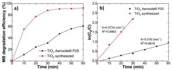
Figure 2.
Comparison between the synthesised TiO2 and commercial Aeroxide ®® P25 TiO2 powders. (a) the degradation efficiency of methylene blue (MB); (b) and the linear kinetic curves.
The nanoparticle coatings were deposited on different polymer substrates such as PMMA, PP, (PS), or PC. Transparent coatings without a significant decrease in transparency could be observed in the case of PMMA. Light transmission measurements showed that the light transmittance of PMMA after the TiO2 layer deposition did not change significantly. The PMMA samples after TiO2 deposition kept 97% of their initial light transmittance (Figure 3). The deposition of TiO2 coatings on the PS, PC, and PP substrates showed a drop in the light transmittance due to the formation of porous structures, as discussed below. A decrease in transmittance was due to light scattering by porous structures. The introduction of the TiO2 coating showed a slight decrease in the contact angle values for deionised water in comparison with the uncoated PMMA substrate (Figure S2).
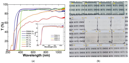
Figure 3.
Optical properties of the produced samples. (a) Light transmittance changes before (0×) and after (1–5×) deposition of the TiO2 coating; (b) produced sample photography showing their translucency.
The SEM images of coatings on different polymer substrates are presented in Figure 4. The produced TiO2 coating on PMMA was homogenous and defect-free. It is worth noting that crack formation is due to the electron beam effect on the surface and is not connected with the coating properties. During SEM imaging, it was observed that cracks became bigger and more prevalent, with an increase in voltage. Before imaging, a 2.2 nm thick Au nanolayer was deposited on the coating surface to avoid surface charging and decrease the electron beam damage. Polypropylene samples showed low coating adhesion with the surface as shown in Figure 4. Large crack formation can be observed, especially with coatings with a larger number of layers. In the case of PS and PC, the formation of pores can be observed that could be related to solvent–polymer interaction. The pores are responsible for turning the substrate white and non-transparent due to light scattering.
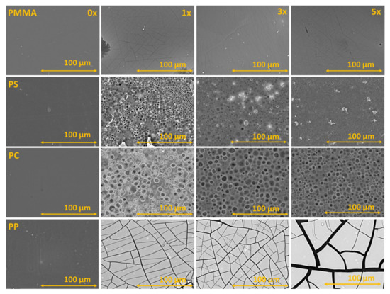
Figure 4.
SEM images of the substrates before coating and with one, three, and five photocatalyst layers.
The SEM images of the TiO2 coating on the PMMA cross-section and surface can be seen in Figure 5. The coating thickness was determined using transmission electron microscopy’s focused ion beam (TEM-FIB) analysis. The coating cross-section showed that the sample thickness for one TiO2 coating was 63 nm, for three it was 200 nm, and for five layers, it was 270 nm. SEM and TEM-FIB showed that the produced coatings were homogenous and uniform in thickness. Similar coherence could be observed in SEM energy dispersion spectroscopy (EDS) (see Figure S3). Correlation between the deposited coating thickness, titanium concentration, and a number of layers can be seen in Supplementary Materials Figure S4.
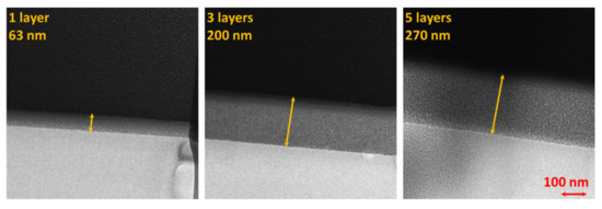
Figure 5.
FIB produced cross-section TEM images of one, three, and five photocatalyst layers on PMMA substrate.
The photocatalytic degradation of rhodamine B is depicted in Figure 6. No significant differences in the degradation rate could be observed between PMMA samples with different numbers of photocatalyst layers (Figure 6a,b). For the uncoated PMMA samples, the amount of decomposed RB dye during 5 h of irradiation varied between 38.42% during the first cycle and 28.90% during the fourth cycle (Figure 6b). For the coated samples, the amount of decomposed dye was in the interval between 79.02% (one layer, fifth cycle) and 93.18% (one layer, second cycle). RB is not UV stable and can degrade via photolysis [18]. It was shown that the half-life of RB decomposition at room temperature, using a 250 W UV source, with the maximum absorption of 2 was 281 min [19]. In our case, the absorption value at spectra maximum on average was 2.1 a.u. and the light source was 100 W. This is a reason that the decomposition rate was lower for the control samples here than stated in the literature.
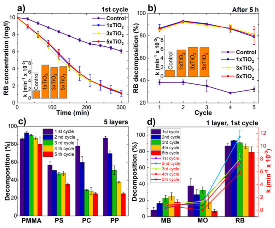
Figure 6.
Photocatalytic activity measurements of TiO2 coatings on the PMMA substrate using RB during: (a) the first cycle; (b) summary during all five cycles; (c) comparison of PMMA and other polymers; (d) and comparison between RB and other organic dyes.
The TiO2 coatings on PMMA were stable during all five testing cycles. An insignificant decrease in the decomposed dye amount for TiO2 coatings on PMMA can be observed between the first and fifth cycle (7–5%) (Figure 6b). The photocatalytic activity evaluation using RB degradation of one TiO2 coating layer on PMMA, PS, PC, and PP can be seen in Figure 6c. The photocatalytic activity for coatings on other polymer substrates was lower and more unstable in comparison with PMMA. The lower photocatalytic activity and degradation rate can be related to inhomogeneous and loosely bonded coatings. In addition, the coatings on other polymer substrates were less stable when compared with coatings on PMMA. The lowest stability could be observed when the substrate material was used PP. This can be attributed to poor TiO2 nanoparticle adhesion to the substrate, as discussed above. For PC, a significant decrease in photocatalytic activity was observed during the first two cycles due to separation of loose TiO2 particles. After the second cycle, the coating became stable. More detailed information about photocatalytic activity using different organic dye solutions could be found in Supplementary Information (Figures S5–S7).
Coating durability on PMMA was analysed based on a SEM image comparison before and after the photocatalysis tests in Figure 7. The SEM images showed a visible degradation in all coatings. Significant loss of the TiO2 coating could be observed for almost all samples after the photodegradation of organic dyes. The highest levels of degradation could be observed for samples that were studied using the degradation of methyl orange. The observed layer separation corresponded to a dramatic decrease in dye degradation speeds during repeated experiments using MO. The coating degradation for rhodamine B samples was less prevalent than in methyl orange. The RB photocatalyst losses corresponded to the level of degradation of dye reported in Figure 6. After the degradation of methylene blue, the photocatalyst layer degradation was less observable, which corresponded to the adsorption phenomena of MB, as previously stated. A similar trend could also be observed using optical microscopy (Figure S8).
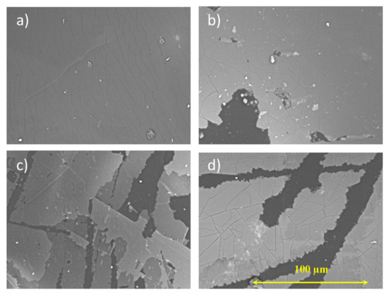
Figure 7.
The SEM images for the TiO2 coatings containing three photocatalyst layers on (a) PMMA before and (b) after dye degradation with MB, (c) MO, and (d) RB.
The XPS spectra of the TiO2 coating before and after photocatalysis can be found in Figure 8. The Ti 2p spectra showed no significant changes in the TiO2 layer, and no formation of Ti3+ species, except after MO photocatalysis. The Ti 2p spectra showed the presence of Ti3+ species in samples with a different number of photocatalyst layers when used for MO degradation. The oxygen O 1s spectra showed characteristic TiO2 lattice oxygen in all of the measured samples with the TiO2 coating. The relative amount of lattice oxide decreased quite significantly, which can be explained by organic dye adsorption on the analysed sample surface and the exposure of PMMA substrate in the analysed area due to coating loss. In the case of methyl orange, the adsorption of Na can be detected, based on sodium Auger peaks. The XPS spectra of C 1s showed all functional groups of PMMA [20]. Differences in the individual peak intensities can be attributed to the TiO2 coating intermitter layer and surface contaminant formation. It is possible that adsorbed organic dyes give their signal in C 1s XPS spectra [21]. XPS spectra for all coatings on PMMA can be found in the Supplementary Materials (Figures S9–S12).
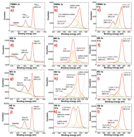
Figure 8.
XPS measurements of high-definition scans of Ti 2p, O 1s, and C 1s spectra. (a–c) before photocatalysis (PMMA samples) and after photocatalysis using (d–f) MB; (g–i) MO and (j–l) RB, respectively.
3. Discussion
Durable and photocatalytically active TiO2 nanoparticle coatings were obtained on various organic substrates at room temperature. Deposition is enabled by ultra-small TiO2 ligand-free nanoparticles with a size below 4 nm. Stripped TiO2 nanoparticles showed strong particle–particle interaction [22], which is responsible for the formation of dense coatings. This was confirmed by the SEM of cross-sections. In our approach, particles do not agglomerate, thus transparent coatings can be obtained on the PMMA substrate. The transparency also depends on the substrate material and solvent used. Substrates such as PC and PS cannot be applied for nanoparticle systems in DMF because porous non-transparent structures are formed. This could be related to the high solubility of the substrate material and precipitation by solvent exchange with air humidity.
TiO2 coatings showed photocatalytic activity for the degradation of various organic substances under UV irradiation, as expected. Overall, the coating showed high photocatalytic activity, thanks to small particle size and their crystalline anatase structure. Our synthesised TiO2 nanoparticles showed much higher photocatalytic activity in comparison with the commercially available Aeroxide®® P25 (Figure 2). The high photocatalytic activity can be related to the high charge mobility of the anatase phase and small particle size comparable to the photoinduced charge carrier diffusion length 120–1000 nm [23]. High photocatalytic activity can be explained with small particle size, which was 5–6 times smaller than P25. It is well-reported that the particle size is a crucial factor in the rates of electron-hole recombination [24]. It has been repeatedly demonstrated that the smaller particles showed faster degradation kinetics [25]. Charge had aa shorter distance to reach the surface for catalytic reactions, thus decreasing the probability of recombination.
The photocatalytic activities for the TiO2 coatings obtained by different methods are compared in Table 1. However, it is hard to compare the photocatalytic activity from one work to another due to different experimental conditions. Considering the sample area and dye concentration, the rate constants for dye degradation at our work were relatively high. Our samples were in between the most active among the coatings listed in Table 1.

Table 1.
Comparison of the different photocatalytic coatings found in the literature.
Photocatalytic TiO2 coatings on PMMA showed good stability over five dye degradation cycles. However, some delamination from the substrate could be observed from cycle to cycle. This can be attributed to the photocatalytic degradation of the substrate material. This could be eliminated by introducing an inert intermediate layer such as SiO2 and will be addressed in future studies.
4. Materials and Methods
4.1. Synthesis of TiO2 Nanoparticles
TiO2 nanoparticle synthesis is based on the modified version presented by Emmanuel Scolan and Clement Sanchez [37] where 9.05 mL of titanium tetra n-butoxide (97%, Sigma-Aldrich, St. Louis, MO, USA) is added dropwise to the mixture containing 12.358 mL n-butanol (≥99.5%, Merck, stored over CaH2, Germany) and 8.268 mL of acetylacetone (≥99%, Merck, China). After the addition of the precursor, the reaction mixture was brought to the boiling point. A preheated mixture of 4.865 g of deionised water and 1.76 g of 4-dodecylbenzene sulfonic acid (4-DDBSA) (≥95%, Sigma-Aldrich, Germany) was added to the reaction mixture dropwise. After the addition of 4-DDBSA, the solution was refluxed overnight. The next day, the solution was cooled, and the formation of yellowish particles was observed. The precipitate was washed twice with methanol (gradient grade for liquid chromatography, Supelco, Germany) and centrifuged (2-16P, Sigma, Germany) at 2000 g for 1 h. After the last washing, particles were allowed to separate at 4000 g for 1 h. After the washing, particles were dispersed in N,N dimethylformamide (DMF) (99%, Merck, Poland) with a concentration of 100 g/l [38].
Before the deposition of films, the surfactant was removed from the particles. A total of 39 mL of hexane (≥97%, Merck, Israel) was added to the 13 mL of TiO2 colloid in DMF and 13 mL of triethyloxonium tetrafluoroborate (EtO3BF4) (≥97%, Sigma-Aldrich, Switzerland) solution in dichloromethane (DCM) (for analysis, Supelco, Germany) (20 mg/mL) was added dropwise, followed by 20 mL of toluene (≥99.7%, Merck, Israel). The solution was mixed for a short amount of time and allowed to separate. As previously stated, the large volume of solution was decanted, and the precipitate was washed with methanol. After washing cycles, solids were dispersed in DMF with a concentration of 100 g/l. The solution was used immediately after preparation [39].
4.2. Coating Deposition
Commercially available polymer samples with dimensions of 25 × 25 × 4 mm were used for all experiments. Before the deposition, polymer substrates were washed with ethanol and treated using plasma (PDC-002-CE, Harrick Plasma, Ithaca NY, USA, setting: high) for 15 min. Coatings were fabricated using a custom-made spin coater. Coatings were deposited at 1500 rpm for 30 s, allowing the DMF to evaporate between layers. Samples containing one, three, and five layers were produced. The solvent was chosen due to its ability to partially dissolve the studied polymers (except PP) to improve the adhesion of the photocatalytically active layers on the substrate.
4.3. Sample Characterisation
The particles were characterised using Raman spectroscopy (inVita, Renishaw, Wotton-under-Edge, UK), XRD (X’Pert, PANalytical, Malvern, United Kingdom), and TEM (Tecnai G20, FEI, Waltham, MA, USA) imaging at 200 kV. The samples for TEM analysis were placed on a perforated carbon film on a 400-mesh copper grid (S147-4, Agar Scientific, Stansted, UK). The particle size distribution was determined using ImageJ 1.53K software [40]. Band gap energy was determined by DRS measurements (SolidSpec-3700, Shimadzu, Japan), Absorption data were calculated by the Kubelka–Munk theory from the reflectance data. Coatings were examined using XPS (ESCALAB Xi+, Thermo Scientific, Waltham, MA, USA) before and after the photocatalysis tests. The residual charging on the sample surface was compensated by using automatic built-in charge compensation tools [41]. Experimental data were fitted using Avantage 5 software using an advantageous carbon peak at 284.8 eV as a calibration point [42]. Coatings before and after the photocatalysis tests were studied using an optical microscope (DM LP, Leica with Leica DC digital camera, Wetzlar, Germany), SEM (TM 3000, Hitachi, Tsukuba, Japan), and EDS. Coating thickness was determined using SEM-FIB produced lamellas (Lyra, Tescan SEM with micromanipulator, 30 kV current, STEM 3+ detector, Czech Republic) in TEM. The surface contact angle was measured using deionised water and diiodomethane (stabilised by copper, Sigma-Aldrich, India) to calculate the surface free energy (SFE) values (Drop shape analyser, Kruss, Hamburg, Germany).
4.4. Photocatalysis Test
Photocatalytic activity of the TiO2 coatings was estimated following a modified version of the ISO 10678:2010 standard [43] by the degradation of organic dyes such as methylene blue (Sigma-Aldrich, India), methyl orange (Sigma-Aldrich, India), and rhodamine B (≥95% for HPLC, Sigma-Aldrich, St. Louis, MO, USA) in deionised water with a concentration of 10 mg/L. A glass cylinder, with an inside diameter of 20 mm, was placed on the coating surface and fixed in place using silicon oil (DC 200, Fluka, Switzerland). Silicon oil is needed to avoid the outflow of dye solution and ease the removal of cylinders after the test. During the experiment, 2 mL of dye solution was added to the glass cylinders and covered with a glass plate. A schematic depiction of the photocatalysis measurement setup is shown in Supplementary Figure S13 [44,45]. Before the irradiation, the samples were left in a dark dye solution for 12 h at room temperature to achieve an adsorption–desorption equilibrium of dye on the surface. After adsorption, the dye solution was replaced with the fresh one. Samples were irradiated in a dark box with a UV light source (Black-Ray®® B-100AP, UVP, 365 nm, 100 W mercury spot lamp, Upland, CA, USA) 20 cm above the sample surface. Samples were stirred every 30 min by using a single-use pipette. Sample of a 1.5 mL was taken and transferred to a PMMA semi-micro cuvette for the measurement of absorbance spectra using a UV–Vis spectrophotometer (Genesys 10S, Thermo Scientific, China). The dye decomposition was calculated by following the decrease in the intensity of each dye’s maximum absorbance values at 664, 465, and 554 nm for methylene blue, methyl orange, and rhodamine B, respectively. The measured absorption spectra for different dye solutions are demonstrated in Supplementary Figure S14. After measuring the absorption spectra, the dye solution was transferred back to the glass cylinder [46]. The measurement was repeated at certain time intervals for a final test duration of 5 h. The dye concentration was calculated based on a calibration graph that was recalibrated before every measurement [46].
The photocatalytic activity of laboratory made TiO2 nanoparticles were compared to the commercially available TiO2 nanopowders (Acros Organics, Aeroxide ®® P25 with an average particle size of 25 nm, Belgium). A total of 0.8 mg/mL was dispersed in MB solution (5 ppm) using sonification. The suspension was placed under UV light with vigorous stirring. A 1.5 mL sample was collected every 10 min and centrifuged for 5 min to avoid nanoparticle effects on the UV–Vis measurements. Samples were analysed over a 60 min period.
The dye decomposition was calculated from the concentration change [47] following Equation (1) [47,48]:
where C0 is the initial concentration of used dye and Ct is the dye concentration at time “t”.
The kinetics of dye decomposition can be described as a pseudo-first-order kinetic reaction. The pseudo-first-order reactions can be expressed in Equations (2) and (3) [49]:
where K is the kinetical constant of the pseudo-first-order reaction (min−1), C0 is the initial concentration of organic dye, and C is a specific concentration in given time t (min). Kinetic constant K was determined by the ln(C0/C) vs. t plot. Since the R2 value for most of the plots was higher than 0.95, the experimental data can be attributed to the pseudo-first-order kinetic reaction model [23].
For a better understanding of different dye photochemical degradation, the relative decomposition in comparison with the uncoated control samples was calculated:
5. Conclusions
In this work, we demonstrated how it is possible to obtain durable and optically clear TiO2 coatings on PMMA by using ultra-small TiO2 nanoparticles. TiO2 coatings on PMMA demonstrated 97% light transmittance compared with the uncoated substrate without significant surface damage. The produced coatings demonstrate good photocatalytic properties in UV light with repeatable results. The RB degradation rate dropped 5–7 % between the first and fifth cycle. It is possible to obtain TiO2 coatings on different polymers but the interaction of DMF and the polymer surface creates defects, which lead to the loss of transparency and poorer photocatalytic degradation rates. A simple and easy method was demonstrated for obtaining TiO2 coatings on a PMMA substrate with enhanced photocatalytic properties.
Supplementary Materials
The following supporting information can be downloaded at: https://www.mdpi.com/article/10.3390/ijms232112936/s1.
Author Contributions
Conceptualisation, A.Š., R.E. and M.I.; Methodology, M.I., R.E. and K.Š.; Software, K.Š. and M.I.; Validation, A.Š. and T.J.; Formal analysis, A.Š. and M.I.; Investigation, M.I. and A.Š.; Resources, A.Š. and T.J.; Data curation, M.I. and R.E.; Writing—original draft preparation, M.I. and R.E.; Writing—review and editing, A.Š. and T.J.; Visualisation, A.Š., M.I. and R.E.; Supervision, A.Š. and T.J.; Project administration, T.J.; Funding acquisition, T.J. All authors have read and agreed to the published version of the manuscript.
Funding
This project has received funding from the European Union’s Horizon 2020 FET Open program under Grant Agreement No. 899528.
Informed Consent Statement
Not applicable.
Data Availability Statement
Not applicable.
Conflicts of Interest
The authors declare no conflict of interest.
References
- Senarathna, U.L.N.H.; Fernando, S.S.N.; Gunasekara, T.D.C.P.; Weerasekera, M.M.; Hewageegana, H.G.S.P.; Arachchi, N.D.H.; Siriwardena, H.D.; Jayaweera, P.M. Enhanced Antibacterial Activity of TiO2 Nanoparticle Surface Modified with Garcinia Zeylanica Extract. Chem. Cent. J. 2017, 11, 7. [Google Scholar] [CrossRef] [PubMed]
- Cedillo-González, E.I.; Riccò, R.; Montorsi, M.; Montorsi, M.; Falcaro, P.; Siligardi, C. Self-Cleaning Glass Prepared from a Commercial TiO2 Nano-Dispersion and Its Photocatalytic Performance under Common Anthropogenic and Atmospheric Factors. Build. Environ. 2014, 71, 7–14. [Google Scholar] [CrossRef]
- Chen, D.; Cheng, Y.; Zhou, N.; Chen, P.; Wang, Y.; Li, K.; Huo, S.; Cheng, P.; Peng, P.; Zhang, R.; et al. Photocatalytic Degradation of Organic Pollutants Using TiO2-Based Photocatalysts: A Review. J. Clean. Prod. 2020, 268, 121725. [Google Scholar] [CrossRef]
- Li, R.; Weng, Y.; Zhou, X.; Wang, X.; Mi, Y.; Chong, R.; Han, H.; Li, C. Achieving Overall Water Splitting Using Titanium Dioxide-Based Photocatalysts of Different Phases. Energy Environ. Sci. 2015, 8, 2377–2382. [Google Scholar] [CrossRef]
- Mathur, S.; Kuhn, P. CVD of Titanium Oxide Coatings: Comparative Evaluation of Thermal and Plasma Assisted Processes. Surf. Coat. Technol. 2006, 201, 807–814. [Google Scholar] [CrossRef]
- Hemissi, M.; Amardjia-Adnani, H.; Plenet, J.C. Titanium Oxide Thin Layers Deposed by Dip-Coating Method: Their Optical and Structural Properties. Curr. Appl. Phys. 2009, 9, 717–721. [Google Scholar] [CrossRef]
- Chen, Z.; Dündar, I.; Oja Acik, I.; Mere, A. TiO2 Thin Films by Ultrasonic Spray Pyrolysis. IOP Conf. Ser. Mater. Sci. Eng. 2019, 503, 012006. [Google Scholar] [CrossRef]
- Nagasawa, H.; Xu, J.; Kanezashi, M.; Tsuru, T. Atmospheric-Pressure Plasma-Enhanced Chemical Vapor Deposition of UV-Shielding TiO2 Coatings on Transparent Plastics. Mater. Lett. 2018, 228, 479–481. [Google Scholar] [CrossRef]
- Shahmohammadi, M.; Nagay, B.E.; Barão, V.A.R.; Sukotjo, C.; Jursich, G.; Takoudis, C.G. Atomic Layer Deposition of TiO2, ZrO2 and TiO2/ZrO2 Mixed Oxide Nanofilms on PMMA for Enhanced Biomaterial Functionalization. Appl. Surf. Sci. 2022, 578, 151891. [Google Scholar] [CrossRef]
- Phuinthiang, P.; Trinh, D.T.T.; Channei, D.; Ratananikom, K.; Sirilak, S.; Khanitchaidecha, W.; Nakaruk, A. Novel Strategy for the Development of Antibacterial TiO2 Thin Film onto Polymer Substrate at Room Temperature. Nanomaterials 2021, 11, 1493. [Google Scholar] [CrossRef]
- Teixeira, S.; Magalhães, B.; Martins, P.M.; Kühn, K.; Soler, L.; Lanceros-Méndez, S.; Cuniberti, G. Reusable Photocatalytic Optical Fibers for Underground, Deep-Sea, and Turbid Water Remediation. Glob. Chall. 2018, 2, 1700124. [Google Scholar] [CrossRef]
- Eglitis, R.; Zukuls, A.; Viter, R.; Šutka, A. Kinetics of TiO2 Photochromic Response in Different Hole Scavenging Solvents. Photochem. Photobiol. Sci. 2020, 19, 1072–1077. [Google Scholar] [CrossRef]
- Frank, O.; Zukalova, M.; Laskova, B.; Kürti, J.; Koltai, J.; Kavan, L. Raman Spectra of Titanium Dioxide (Anatase, Rutile) with Identified Oxygen Isotopes (16, 17, 18). Phys. Chem. Chem. Phys. 2012, 14, 14567. [Google Scholar] [CrossRef]
- Choi, H.C.; Jung, Y.M.; Kim, S. Bin Size Effects in the Raman Spectra of TiO2 Nanoparticles. Vib. Spectrosc. 2005, 37, 33–38. [Google Scholar] [CrossRef]
- Zhang, W.F.; He, Y.L.; Zhang, M.S.; Yin, Z.; Chen, Q. Raman Scattering Study on Anatase TiO2 Nanocrystals. J. Phys. D Appl. Phys. 2000, 33, 912–916. [Google Scholar] [CrossRef]
- Biesinger, M.C.; Lau, L.W.M.; Gerson, A.R.; Smart, R.S.C. Resolving Surface Chemical States in XPS Analysis of First Row Transition Metals, Oxides and Hydroxides: Sc, Ti, V.; Cu and Zn. Appl. Surf. Sci. 2010, 257, 887–898. [Google Scholar] [CrossRef]
- Tanuma, S.; Powell, C.J.; Penn, D.R. Calculations of Electron Inelastic Mean Free Paths. V. Data for 14 Organic Compounds over the 50-2000 EV Range. Surf. Interface Anal. 1994, 21, 165–176. [Google Scholar] [CrossRef]
- Zhu, C.; Lu, B.; Su, Q.; Xie, E.; Lan, W. A Simple Method for the Preparation of Hollow ZnO Nanospheres for Use as a High Performance Photocatalyst. Nanoscale 2012, 4, 3060–3064. [Google Scholar] [CrossRef]
- Blažeka, D.; Car, J.; Klobučar, N.; Jurov, A.; Zavašnik, J.; Jagodar, A.; Kovacevic, E.; Krstulović, N.; Kovačevi’c, E.K.; Krstulovi’ckrstulovi’c, N. Photodegradation of Methylene Blue and Rhodamine B Using Laser-Synthesized ZnO Nanoparticles. Materials 2020, 13, 4357. [Google Scholar] [CrossRef]
- Pijpers, A.P.; Meier, R.J. Core Level Photoelectron Spectroscopy for Polymer and Catalyst Characterisation. Chem. Soc. Rev. 1999, 28, 233–238. [Google Scholar] [CrossRef]
- Zheng, J.; Xia, L.; Song, S. Electrosorption of Pb(II) in Water Using Graphene Oxide-Bearing Nickel Foam as the Electrodes. RSC Adv. 2017, 7, 23543–23549. [Google Scholar] [CrossRef]
- Ofosu, C.K.; Truskett, T.M.; Milliron, D.J. Solvent-Ligand Interactions Govern Stabilizing Repulsions between Colloidal Metal Oxide Nanocrystals. ChemRxiv 2022. [Google Scholar] [CrossRef]
- Zheng, J.; Zhou, H.; Zou, Y.; Wang, R.; Lyu, Y.; Jiang, S.P.; Wang, S. Efficiency and Stability of Narrow-Gap Semiconductor-Based Photoelectrodes. Energy Environ. Sci. 2019, 12, 2345–2374. [Google Scholar] [CrossRef]
- Zhang, Z.; Wang, C.-C.; Zakaria, R.; Ying, J.Y. Role of Particle Size in Nanocrystalline TiO2-Based Photocatalysts. J. Phys. Chem. B 1998, 102, 10871–10878. [Google Scholar] [CrossRef]
- Lin, H.; Huang, C.; Li, W.; Ni, C.; Shah, S.; Tseng, Y. Size Dependency of Nanocrystalline TiO2 on Its Optical Property and Photocatalytic Reactivity Exemplified by 2-Chlorophenol. Appl. Catal. B 2006, 68, 1–11. [Google Scholar] [CrossRef]
- Choi, H.; Stathatos, E.; Dionysiou, D.D. Sol-Gel Preparation of Mesoporous Photocatalytic TiO2 Films and TiO2/Al2O3 Composite Membranes for Environmental Applications. Appl. Catal. B 2006, 63, 60–67. [Google Scholar] [CrossRef]
- Mathews, N.R.; Morales, E.R.; Cortés-Jacome, M.A.; Toledo Antonio, J.A. TiO2 Thin Films-Influence of Annealing Temperature on Structural, Optical and Photocatalytic Properties. Sol. Energy 2009, 83, 1499–1508. [Google Scholar] [CrossRef]
- Pore, V.; Rahtu, A.; Leskelä, M.; Ritala, M.; Sajavaara, T.; Keinonen, J. Atomic Layer Deposition of Photocatalytic TiO2 Thin Films from Titanium Tetramethoxide and Water. Chem. Vap. Depos. 2004, 10, 143–148. [Google Scholar] [CrossRef]
- Zhuang, J.; Dai, W.; Tian, Q.; Li, Z.; Xie, L.; Wang, J.; Liu, P.; Shi, X.; Wang, D. Photocatalytic Degradation of RhB over TiO2 Bilayer Films: Effect of Defects and Their Location. Langmuir 2010, 26, 9686–9694. [Google Scholar] [CrossRef]
- Goei, R.; Lim, T.T. Ag-Decorated TiO2 Photocatalytic Membrane with Hierarchical Architecture: Photocatalytic and Anti-Bacterial Activities. Water Res. 2014, 59, 207–218. [Google Scholar] [CrossRef]
- Carneiro, J.O.; Teixeira, V.; Portinha, A.; Magalhães, A.; Coutinho, P.; Tavares, C.J.; Newton, R. Iron-Doped Photocatalytic TiO2 Sputtered Coatings on Plastics for Self-Cleaning Applications. Mater. Sci. Eng. B 2007, 138, 144–150. [Google Scholar] [CrossRef]
- Vaiano, V.; Sacco, O.; Sannino, D.; Ciambelli, P. Nanostructured N-Doped TiO2 Coated on Glass Spheres for the Photocatalytic Removal of Organic Dyes under UV or Visible Light Irradiation. Appl. Catal. B 2015, 170–171, 153–161. [Google Scholar] [CrossRef]
- Fu, P.; Luan, Y.; Dai, X. Preparation of Activated Carbon Fibers Supported TiO2 Photocatalyst and Evaluation of Its Photocatalytic Reactivity. J. Mol. Catal. A Chem. 2004, 221, 81–88. [Google Scholar] [CrossRef]
- Soni, S.S.; Henderson, M.J.; Bardeau, J.F.; Gibaud, A. Visible-Light Photocatalysis in Titania-Based Mesoporous Thin Films. Adv. Mater. 2008, 20, 1493–1498. [Google Scholar] [CrossRef]
- Yaghoubi, H.; Taghavinia, N.; Alamdari, E.K. Self Cleaning TiO2 Coating on Polycarbonate: Surface Treatment, Photocatalytic and Nanomechanical Properties. Surf. Coat. Technol. 2010, 204, 1562–1568. [Google Scholar] [CrossRef]
- Tavares, C.J.; Vieira, J.; Rebouta, L.; Hungerford, G.; Coutinho, P.; Teixeira, V.; Carneiro, J.O.; Fernandes, A.J. Reactive Sputtering Deposition of Photocatalytic TiO2 Thin Films on Glass Substrates. Mater. Sci. Eng. B Solid State Mater. Adv. Technol. 2007, 138, 139–143. [Google Scholar] [CrossRef]
- Scolan, E.; Sanchez, C. Synthesis and Characterization of Surface-Protected Nanocrystalline Titania Particles. Chem. Mater. 1998, 10, 3217–3223. [Google Scholar] [CrossRef]
- Sutka, A.; Eglitis, R.; Kuzma, A.; Smits, K.; Zukuls, A.; Prades, J.D. Photodoping-Inspired Room-Temperature Gas Sensing by Anatase TiO2 Quantum Dots. ACS Appl. Nano Mater. 2021, 4, 2522–2527. [Google Scholar] [CrossRef]
- Dong, A.; Ye, X.; Chen, J.; Kang, Y.; Gordon, T.; Kikkawa, J.M.; Murray, C.B. A Generalized Ligand-Exchange Strategy Enabling Sequential Surface Functionalization of Colloidal Nanocrystals. J. Am. Chem. Soc. 2011, 133, 998–1006. [Google Scholar] [CrossRef]
- Schneider, C.A.; Rasband, W.S.; Eliceiri, K.W. NIH Image to ImageJ: 25 Years of Image Analysis. Nat. Methods 2012, 9, 671–675. [Google Scholar] [CrossRef]
- Baer, D.R.; Artyushkova, K.; Cohen, H.; Easton, C.D.; Engelhard, M.; Gengenbach, T.R.; Greczynski, G.; Mack, P.; Morgan, D.J.; Roberts, A. XPS Guide: Charge Neutralization and Binding Energy Referencing for Insulating Samples. J. Vac. Sci. Technol. A 2020, 38, 031204. [Google Scholar] [CrossRef]
- Miller, D.J.; Biesinger, M.C.; McIntyre, N.S. Interactions of CO2 and CO at Fractional Atmosphere Pressures with Iron and Iron Oxide Surfaces: One Possible Mechanism for Surface Contamination? Surf. Interface Anal. 2002, 33, 299–305. [Google Scholar] [CrossRef]
- ISO 10678:2010 Fine Ceramics (Advanced Ceramics, Advanced Technical Ceramics)—Determination of Photocatalytic Activity of Surfaces in an Aqueous Medium by Degradation of Methylene Blue. Available online: https://www.iso.org/standard/46019.html (accessed on 25 March 2022).
- Guan, S.; Hao, L.; Lu, Y.; Yoshida, H.; Pan, F.; Asanuma, H. Fabrication of Oxygen-Deficient TiO2 Coatings with Nano-Fiber Morphology for Visible-Light Photocatalysis. Mater. Sci. Semicond. Process. 2016, 41, 358–363. [Google Scholar] [CrossRef]
- Loncar, E.; Radeka, M.; Petrovic, S.; Skapin, A.; Rudic, O.; Ranogajec, J. Determination of the Photocatalytic Activity of TiO2 Coatings on Clay Roofing Tile Substrates Methylene Blue as Model Pollutant. Acta Period. Technol. 2009, 40, 125–133. [Google Scholar] [CrossRef]
- Mills, A. An Overview of the Methylene Blue ISO Test for Assessing the Activities of Photocatalytic Films. Appl. Catal. B 2012, 128, 144–149. [Google Scholar] [CrossRef]
- Neren Ökte, A.; Yilmaz, Ö. Photodecolorization of Methyl Orange by Yttrium Incorporated TiO2 Supported ZSM-5. Appl. Catal. B 2008, 85, 92–102. [Google Scholar] [CrossRef]
- Bouarioua, A.; Zerdaoui, M. Photocatalytic Activities of TiO2 Layers Immobilized on Glass Substrates by Dip-Coating Technique toward the Decolorization of Methyl Orange as a Model Organic Pollutant. J. Environ. Chem. Eng. 2017, 5, 1565–1574. [Google Scholar] [CrossRef]
- Jiang, W.; Joens, J.A.; Dionysiou, D.D.; O’Shea, K.E. Optimization of Photocatalytic Performance of TiO2 Coated Glass Microspheres Using Response Surface Methodology and the Application for Degradation of Dimethyl Phthalate. J. Photochem. Photobiol. A Chem. 2013, 262, 7–13. [Google Scholar] [CrossRef]


Publisher’s Note: MDPI stays neutral with regard to jurisdictional claims in published maps and institutional affiliations. |
© 2022 by the authors. Licensee MDPI, Basel, Switzerland. This article is an open access article distributed under the terms and conditions of the Creative Commons Attribution (CC BY) license (https://creativecommons.org/licenses/by/4.0/).