Abstract
Low-frequency oscillations are an inevitable phenomenon of a power system. This paper proposes an Ant lion optimization approach to optimize the dual-input power system stabilizer (PSS2B) parameters to enhance the transfer capability of the 400 kV line in the North-West region of the Ethiopian electric network by the damping of low-frequency oscillation. Double-input Power system stabilizers (PSSs) are currently used in power systems to damp out low-frequency oscillations. The gained minimum damping ratio and eigenvalue results of the proposed Ant lion algorithm (ALO) approach are compared with the existing conventional system to get better efficiency at various loading conditions. Additionally, the proposed Ant lion optimization approach requires minimal time to estimate the key parameters of the power oscillation damper (POD). Consequently, the average time taken to optimally size the parameters of the PSS controller was 14.6 s, which is pretty small and indicates real-time implementation of an ALO developed model. The nonlinear equations that represent the system have been linearized and then placed in state-space form in order to study and analyze the dynamic performance of the system by damping out low-frequency oscillation problems. Finally, conventional fixed-gain PSS improves the maximum overshoot by 5.2% and settling time by 51.4%, but the proposed optimally sized PSS employed with the ALO method had improved the maximum overshoot by 16.86% and settling time by 78.7%.
1. Introduction
Low-frequency oscillation is one of the main problems for power system stability. LFO limits the normal power-transfer capacity of the transmission network, which affects the operational system economics and security. The frequency ranges of low-frequency oscillations are between 0.1 and 3 Hz, which are caused by the connection of a high gain exciter and poorly tuned generator excitation system. If low-frequency oscillations are not damped, they will lead to system instability or complete blackout. To enhance power system stability, the installation of a simple and effective supplementary excitation controller is proposed in this system. In a power system, PSS devices and supplementary controllers were used to keep the balance between demand and generation in a reliable manner with high power quality [1]. The main objective of this manuscript is to damp out low-frequency oscillation through the optimal sizing of the power system stabilizer. The stabilizer parameters are optimally tuned by using the Ant lion optimization technique.
1.1. Motivation and Incitement of the Paper
The motivation of this paper is that there are different problems that occur in power systems. To address these issues, a dual-input power system stabilizer is proposed. The proposed system has the advantage of damping low-frequency oscillation using PSS2B to improve power system stability in the power system network. Instability may occur due to different reasons that happen at the generation station, transmission or at the distribution when a large load is connected to the system. The main effect of low-frequency oscillation is the interruption of power from generation to end-user, and this may cause a breakdown of electrical equipment due to the oscillation generators. Enhancing the dynamic power system stability by damping out of LFO helps to minimize the failure of electrical equipment, as well as the whole power system network.
1.2. Literature Review
Various researchers’ have performed research for mitigating the low-frequency oscillations from the power network.
In [2], the authors presented the dynamic stability enhancement using a PSO algorithm for sizing the power system stabilizer to low-frequency oscillation damping. In [3], the authors investigated the performance of FLC-based adaptive PSS for a SMIB system stability enhancement. In [4], the authors presented particle swarm-optimized PSS to increase the dynamic stability of the entire power system. The authors of [5] presented the proposed controller design of STATCOM using the modified shuffled frog leaping algorithm (MSFL) for LFO damping. In this work, a new MSFL algorithm is proposed for the optimal selection of STATCOM damping controller parameters to shift eigenvalues to the left-hand side of the plane. In [6], the authors described an optimal modal coordination strategy based on modal superposition theory to mitigate low-frequency oscillation in FCWG-penetrated power systems. In [7], the author shows the mitigation of the inter-area oscillation of an interconnected power system by considering the time-varying delay and actuator saturation using renewable energy. In [8], the authors offered optimal damping for a generalized unified power flow controller-equipped single-machine infinite bus system for addressing low-frequency oscillation. In [9], the authors presented the analysis of low-frequency interactions of DFIG wind turbine systems in a series of compensated grids. In [10], the authors discussed the design of an adaptive wide-area damping controller based on delay scheduling for improving small-signal oscillation. In [11], researchers described a UPFC-based stabilizer that adopts a conventional PI controller and a lead-lag controller to produce the damping effect. Because the UPFC covers active and reactive power controls with multiple time scales, the low-frequency damping control parameters of UPFC are hard to design for different operating conditions. In [12], the authors presented a design of an adaptive wide-area damping controller based on delay scheduling for improving small-signal oscillations. In this paper, the damping controllers are properly tuned, and the controller has limited applications. In [13], the authors presented the mitigation of low-frequency oscillations by optimal allocation of power system stabilizers. In this case, single-input PSS is used as a controller, and the damping efficiency of the controller is poor.
1.3. Research Gaps
From the above literature, the dynamic stability of a power system is improved by using a poorly tuned power system stabilizer controller. The performance index of the response to attain a steady-state system takes a large settling time and maximum overshoot to converge. The techniques utilized in the above papers could not be coordinated, and the stability was not improved effectively within a short amount of time. Further, the power system’s stabilizer parameters were estimated to treasure the optimum values of two key PSS parameters (K and T1) by keeping constant values for the other three parameters (T2, T3 and T4), but the result may not be accurate since three out of five parameters are set to be constant to optimize K and T1. However, the proposed ALO-based PSS is used to optimize the parameters of the controller using a multi-objective function. The damping torque provided by the excitation system is not enough for LFO suppression.
1.4. Contribution of the Manuscript
There have been many studies on low-frequency oscillation damping controllers. A power system stabilizer (PSS) in the excitation system is used to generate the damping effect. The PSS suppresses LFOs by controlling the electromagnetic torque variation. The newly designed PSS2B in the excitation system has been proven to be the most cost-effective damping controller compared to the other papers cited in this paper. The main contribution of the proposed approach is that the controllers are optimally sized using the ALO approach to damp out low-frequency oscillations. The power oscillation damping controller has a low controller gain, time constants and small settling time to attain steady-state stability. Moreover, the controller is optimally sized and installed in its proper place. The proposed mathematical models were employed to estimate the respective values of the key parameters in real-time depending on the operating conditions of the power system network. The superiority of the proposed ALO-based PSS system over the above literature was confirmed through the presented minimum damping ratio and eigenvalue analyses, along with the time domain representations of the power system states. In the proposed system, the parameters of the power system stabilizer are optimally sized by ALO to produce electrical torque in phase with speed deviation by the phase compensation technique, which meets the proposed objective function.
The novelties of this paper are as follows:
- In this manuscript, the application of the dual-input PSS with optimally tuned controller parameters uses the most recent ALO technique.
- As presented in the results section, all of the simulation results are superior to the other applied techniques.
- In addition, the authors tried to compare the results of the dual-input PSS with the single-input PSS, base case and classical system.
- Further, a practical utility network was utilized, which is from a developing nation Ethiopia. As in the developing nations, such as Ethiopia, practical systems are facing challenges from the low-frequency oscillations. Further, the system network is going to be upgraded, which makes the LFO problem more complex. Therefore, this work is very helpful for providing the solution to the utility network.
1.5. Organization of the Manuscript
2. Methodology
2.1. Power System Stabilizer
A power system stabilizer is used to improve the damping out of low-frequency oscillation through the excitation control system. The inputs for power system stabilizers are terminal frequency, shaft speed deviation and acceleration power. In this study, the input signal for the single-input PSS model is synchronous machine rotor speed deviation (). The output signal of a PSS is stabilized voltage (). The time constant represents the signal washout time constant and shows the stabilizer gain of PSS. T1–T4 represent the phase compensation time constants [8]. The power system stabilizer output can be restricted by limiter settings in and [9]. In an interconnected system, LFO is one of the main problems faced in power systems. System separation occurs if no sufficient damping is provided to compensate for the insufficiency of the damping torque in the synchronous generator. Low-frequency oscillation problems happen due to the automatic voltage regulator’s exciter high speed and high gain.
Types of Power System Stabilizers
Single-input PSS: The inputs for single-input PSS are the rotor speed deviation (∆ω), the change in frequency (∆f) and the accelerating power (∆Pa). The single-input power system stabilizer (PSS1B) has an input of rotor speed deviation. This stabilizer reduces the damping of the low-frequency oscillations. The structure of PSS1B has parameters such as stabilizer gain K and lead-lag time constants T1–T4.
Dual-input PSS (PSS2B): In this PSS, one input is the rotor speed deviation (∆ω), and another input is the change in electric power (∆). Due to the simplicity of measuring electric power and the relationship with the shaft speed, the change in electric power (∆) is taken as an input signal for the power system stabilizer. The input control signal of PSS2B is electric power deviation (∆Pe), and the parameters to be optimized are the controller gain (K) and time constant (t).
2.2. Sizing of Power System Stabilizer Parameters
Figure 1 shows the block diagram of the power system stabilizer [4], which consists of gain K, washout time constant Tw and phase compensation time constants T1, T2, T3 and T4 [10]. The power system stabilizer produces torque on the rotor to compensate for the phase lag between exciter input and machine electrical torque.
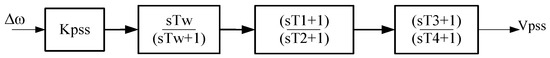
Figure 1.
Single-input power system stabilizer lead-lag structure.
The typical range of time constants and controller gain are shown in the Table 1 below.

Table 1.
Typical range of single-input PSS optimized parameters.
The parameter values of the power system stabilizer are gained by the ALO algorithm by considering low-frequency oscillation.
2.3. Modeling of Power System Stabilizer
The method of incorporating excitation control system models into an LFO damping by considering the excitation system shown in Figure 2 below [10]. The AVR and PSS for excitation system control are presented below.
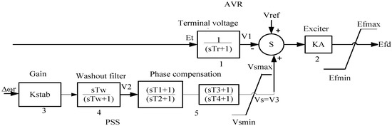
Figure 2.
Thyristor excitation system with AVR and PSS.
The thyristor excitation system with AVR and PSS has different blocks, and the mathematical model is presented as shown below [10]. From block 1 of Figure 2
From blocks 3 and 4,
with, , from block 5
with given by the above equation. The stabilizer output is
with from block 2, the exciter output voltage is
with The initial value of the excitation system variables are
The AVR reference is
Thus, takes the appropriate value of generator operating conditions prior to disturbance.
There are four generating units in the power plant, and there are four power system stabilizers for each unit. The local input signal is better for single-input PSS, while multiple-input PSS requires multiple-input signals, such as rotor speed deviation and active power deviation.
2.4. Dual-Input Power System Stabilizer
The main block diagrams of different dual-input stabilizers under study are shown below. These stabilizer models are sized to represent a variation of dual-input stabilizers, which is a combination of power and speed deviation to stabilizing signal. In PSS2B, for each input, two washout blocks can be represented (Tw1 to Tw4) along with a transducer time constant (T6, T7) and transducer gain constant (Ks2). Time constants (T8–T9) and indices, N and M, allow a ramp-tracking or simpler filter characteristic to be represented. Finally, two lead-lag compensators with time constants are represented by T1 to T4 and the stabilizer output voltage (Vpss) which are presented in Figure 3 below.
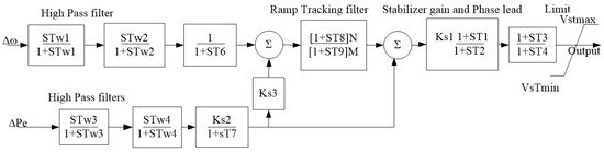
Figure 3.
Dual-input power system stabilizer (PSS2B).
2.5. Problem Formulation
ALO optimization is characterized as the way towards finding the conditions that give the best or most extreme condition of a function, where the function expresses the effort required. Basically, optimization refers to maximizing or minimizing an objective function subject to some specific constraints. In this paper, the main goal of employing the ALO algorithm is to select the optimal parameters for PSS among the different options to operate the system at optimal conditions. Therefore, the ALO algorithm has been selected and used as the optimal tuning method for the proposed paper. To get optimal parameters that improve LFO damping, the problem is formulated to optimize a selected objective function J subjected to gain and time constant inequality constraints.
2.5.1. Objective Function
The primary input signal of PSS is rotor speed deviation, and its main objective is to minimize this speed deviation during the disturbance. This problem has combined two objective functions, the damping factor and the damping ratio. The first function improves the damping factor while the second one sets the damping ratio. The overall multi-objective function J can be described as [14]:
2.5.2. Constraint Equations
The constraint equations are the controller gain K and phase-compensating time constants and the lead-lag time constants T1–T4.
Subject to controller gain:
Phase-compensating time constants:
where, and represent the real part and damping ratio of the ith eigenvalue, respectively. The values of and are 10, −2 and 0.5, respectively. σ0 controls the relative stability in terms of damping factor margin. The main goal of optimization is to maximize the damping ratio. The optimal parameters for single-input PSS are K, , and , but for dual-input PSS, there are additional time constants and gains, such as transducer time constant (T6, T7), time constants (T8–T9) and transducer gain constant (Ks2). There are also two washout blocks with washout time constants (Tw1 to Tw4).
Figure 4a shows the first objective function (J1), which carries out the eigenvalues towards the left of the -axis. Similarly, Figure 4b represents the second objective function (J2) that limits the maximum overshoot of the eigenvalues by restricting a specific region. When the two objective functions are considered, the eigenvalues are limited to a D-shaped region, as shown in Figure 4c below.
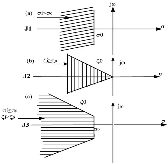
Figure 4.
Region of location of eigenvalues for objective functions.
Figure 4a shows the objective functions which forces the damping factor to the negative axis and Figure 4b shows the damping ration of the eigenvalues that limits the overshoot while Figure 4c shows the intersection point of the objective function. The optimal values are obtained by ALO technique as shown in Table 2 below.
Table 2.
Typical range of dual-input optimized parameters.
For PSS2B and .
3. Ant Lion Optimization Problem
The recently developed ALO technique is a new meta-heuristic optimization approach. It was introduced by Seyedali Mirjalili [11]. The inspiration for ALO comes from the real-life analysis of the ALO hunting mechanism in nature. The ALO technique mimics the hunting strategy of antlions in nature. The five steps of the hunting mechanism are the random walk of ants, building traps, entrapment of ants in traps, catching prey and rebuilding traps.
3.1. Operators of ALO Algorithm
The ALO algorithm mimics the interaction between antlions and ants in the trap. In order to represent such interactions, ants are required to move in the search space and antlions are allowed to hunt the ants and become fitter using traps. The random walk of ants is as follows:
where represents the cumulative sum, n is the maximum number of iterations, t represents the steps of the random walk and r(t) is a stochastic function, which is represented as:
where t represents the random walk of ants and rand is a random number generated with uniform distribution in the interval of [0, 1]. The position of the ants is saved and utilized during optimization in the following matrix:
where is the matrix for saving the position of each ant, shows the value of the variable of ant, n is the number of ants and d is the number of variables. The position of an ant refers to the parameters for a particular solution. Matrix has been considered to save the position of all ants during optimization.
where MoA is the matrix for saving the fitness of each ant, shows the value of dimension of ant, n is the number of ants and f is the objective function.
where is the matrix for saving the position of each antlion, ALi,j shows the dimension’s value of the antlion, n is the number of antlions and d is the number of variables.
where MoAL is the matrix for saving the fitness of each ant lion, shows the dimension’s value of the antlion, n is the number of antlions and f is the objective function.
3.2. Random Walk of Ants
Ants update their positions with a random walk at every step of the optimization. To keep the random walks inside the search space, they are normalized using the following equation:
where is the minimum of random walk of the variable, is the maximum random walk of the variable, is the minimum of the variable at the iteration and indicates the maximum of the variable at the iteration. The formula for updating the position of ants is presented in Equation (22) below. It should be applied to guarantee the occurrence of RWs inside the search space.
3.3. Trapping in Ant Lion’s Pit
In order to mathematically model this assumption, the following equations are proposed:
where represents the minimum of all variables at the iteration, indicates the vector including the maximum of all variables at the iteration, represents the minimum of all variables for the ant, is the maximum of all variables for the ant and shows the position of the selected antlion at the iteration.
3.4. Sliding Ants towards Ant Lion
This behavior slides down the trapped ant that is trying to escape. The following equations are proposed in this regard:
where I is a ratio, is the minimum of all variables at the iteration and represents the vector, including the maximum of all variables at the iteration. In Equations (16) and (17), , where t is the current iteration, T is the maximum number of iteration, and w is defined based on the current iteration (w = 2 when t > 0.1 T, w = 3 when t > 0.5 T, w = 4 when t > 0.75 T, w = 5 when t > 0.9 T and w = 6 when t > 0.95 T). The parameter w in the equation for I is able to adjust the accuracy level of the exploitation.
3.5. Catching Prey and Rebuilding Pit
The last stage of the hunt is when an ant reaches the bottom of the pit and is caught in the antlions jaw. The following equation is proposed:
Where t shows the current iteration, shows the position of selected antlion at the iteration and indicates the position of the ant at the iteration.
3.6. Elitism
Elitism is a characteristic of evolutionary algorithms, which allows them to keep the best solution obtained at any stage of the optimization process. Since the elite is the fittest antlion, it should affect the movement of all ants during the iteration. The elite and updating the position of ants is:
where is the random walk around that the antlion selected by roulette wheel at the iteration, is the random walk around of the elite at the iteration and indicates the position of the ant at the iteration.
The pseudo-codes of the ALO algorithm (Algorithm 1) are defined as follows:
| Algorithm 1. The pseudo-codes of the ALO algorithm |
| Initialize the first population of ants and antlions randomly Calculate the fitness of ants and antlions Find the best antlions and assume it as the elite (determined optimum) While the end criterion is not satisfied for every ant Select an antlion using Roulette wheel Update c and d using equations above Create a random walk and normalize it given by the above equations in the random walk Update the position of ant using Equation (22) end for Calculate the fitness of all ants Replace an antlion with its corresponding ant it if becomes fitter Update elite if an antlion becomes fitter than the elite end while Return elite |
3.7. Optimal Sizing of Single-Input PSS
The five optimal parameters of PSS are four time constants T1–T4 and gain , which is optimally selected and sized by the ALO algorithm to guarantee optimal system performance of the generator under various system configurations. The optimality intended in this paper is to find the best parameter sizes for PSS. PSS could generate torque on the rotor of electrical machines, and hence phase lag between exciter input and machine electrical torque is compensated. The main purpose of sizing PSS and POD parameters is to ensure the appropriate phase lead to compensate for the phase lag resulting from the generator excitation system, and the parameters are optimized to provide the appropriate phase lead. Figure 5 and Table 3 show the optimal parameters of PSS tuned by ALO for exciter input.
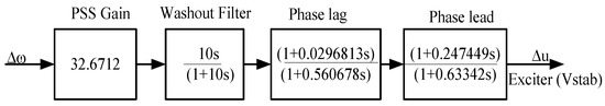
Figure 5.
Optimally sized power system stabilizer lead-lag structure.
Table 3.
Optimal parameter values of power system stabilizer employing ALO.
3.8. Optimal Parameter Sizing of Dual-Input PSS
The SMIB system is the best to start evaluating any proposed control strategy in a power system. The optimal parameters of the dual-input PSS are optimally selected and sized by the ALO algorithm to guarantee optimal system performance of the generator under various system configurations. Dual-input PSS could generate torque on the rotor of electrical machines, so phase lag between the exciter input and machine electrical torque is compensated. The main purpose of sizing the dual-input PSS parameters is to ensure the appropriate phase leads to the compensation of the phase lag resulting from the generator excitation system in a complex power system of SMIB. The input signals to this PSS are speed deviation and electrical power deviation from the synchronous generator. The limits of the input signals, which represent the allowable ranges of the sensed values, depending on specific design parameters. For each input, two washout blocks can be represented (Tw1–Tw4), along with transducer time constants (T6 and T7). A torsional filter (time constants T8 and T9) with indices M = 5 and N = 1 is provided. The VSMAX and VSMIN are, respectively, the maximum and minimum limits of the stabilizer output. and pu are used in practice [15]. The derived speed deviation signal has a relatively low level of torsional components and is fed to a pair of cascade-connected lead-lag networks. The optimal parameters of dual-input power system stabilizer are presented in Table 4 below.
Table 4.
Optimal parameter values of dual-input power system stabilizer using ALO.
The structure of optimally sized power system stabilizer are presented in Figure 6 below.
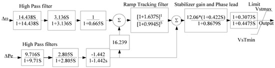
Figure 6.
Optimally sized power system stabilizer lead-lag structure.
3.9. Overall System Diagram with MATLAB Simulink
The considered electric network consists of Tana Beles power plant, as mentioned in Appendix A, equipped with PSS and an infinite bus, which are interconnected through a transmission line. The parameters of the damping controllers for individual and coordinated sizing are optimized utilizing the ALO technique based on the eigenvalue objective function. The proper selection of PSS parameters is the damping of LFO to improve power system stability. The PSS is installed at the power plant generator excitation system to supply the stabilized voltage.
The overall power system network equipped with PSS is presented in Figure 7 and Figure 8. Figure 8 presents the implementation of the power system network in Matlab Simulink that shows the experimental test case system. The overall power system is used to implement the experimental test system of the proposed cases. Therefore, the power system is constructed with a Tana Beles power plant, five buses, a 400 kV double-circuit transmission line and a 230 kV infinite grid at the Bahirdar substation. Figure 8 shows the main components and circuit organization of a Tana Beles power plant that is interconnected with a hydraulic turbine, excitation system, power system stabilizer and synchronous generator. In this power plant, the input to PSS is the active power and rotor speed deviation, while the output signal is stabilized voltage, which is directly connected to the excitation system.
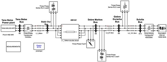
Figure 7.
Overall power system network.
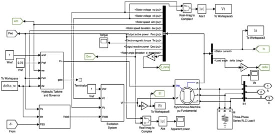
Figure 8.
Schematic diagram of dual-input PSS with excitation system.
4. Result and Discussion
4.1. Time Domain Simulation Analysis
Power system stability depends on controller gain K and time constants (T1–T4), these parameters must be optimized, and the mentioned objective function (J) has the same requirement. Consequently, the objective function of this paper alters the maximizing and the minimum damping ratios. Table 5 shows the optimized parameters of the coordinated controllers obtained by ALO, GA, PSO and TLBO.
Table 5.
Comparison of simulation results of different algorithms.
Table 6 shows the optimized parameters of the coordinated controllers obtained of dual input PSS by ALO, GA, PSO and TLBO.
Table 6.
Optimal parameter values of the dual-input power system stabilizer.
Table 7 shows the optimized parameters values of the washout time constant for dual input PSS obtained by ALO, GA, PSO and TLBO.
Table 7.
Parameter values of washout time constant for dual-input PSS.
From the above table, the gain of the proposed ALO technique is less than the remaining methods, which avoids the adverse interaction with active power generation and amplification of high-frequency noise. Further, the computational time to optimally tune the parameters of the controller is small compared to the others. The recorded average times to optimally tune PSS parameters were approximately 15.5314, 55.909, 106.3817 and 203.4058 s for ALO, GA, PSO and TLBO, respectively. Consequently, the average time required to tune the parameters of ALO-based PSS was 15.5314 s, which is pretty small and indicates real-time implementation of the ALO-developed model in a power system and the proposed method is fast, which confirms the superiority of the developed method.
Eigenvalue Analysis and Minimum Damping Ratio
The system is stable if all eigenvalues have negative real parts. If any one of the eigenvalues has a positive real part, then the system is unstable, or if the eigenvalues have a real part equal to zero, then the poles are complex with only the imaginary part locating on the j axis. In order to obtain robust controllers, eigenvalue analysis and the minimum damping ratio of three operating conditions have been compared and discussed in Table 8 below. Synchronous machine variables, such as real and reactive powers, with their terminal voltage (P0, Q0 and Ut) are considered as the loading conditions. The ranges of values for the selected variables are 0.2 ≤ P0 ≤ 1.2, 0.01 ≤ Q0 ≤ 0.4 and 0.6 ≤ Ut ≤ 1.
Table 8.
Eigenvalues and minimum damping ratios of different loading conditions.
The overall system for a Tana Beles 400 kV line is simulated for different loading conditions, and the minimum damping ratios are tabulated in Table 8 for the base case system, PSS1B and ALO-based PSS2B. The ALO-based, optimally tuned PSS2B model has a better performance than the base case system and PSS for each case only in terms of the minimum damping ratio.
4.2. Simulation Output Results at Each Bus
The objective of the LFO study was to ascertain whether the designed system could damp out low-frequency oscillation and return to a steady value following the clearance of the disturbance. However, in this paper, the simulation results for parameters, such as rotor angle deviation, rotor speed deviation, active power, reactive power, rotor/load angle, excitation voltage, rotor speed, terminal voltage, and positive sequence voltage, are provided to clearly show that the damping out of the low-frequency oscillation in power system stability enhancement.
However, when the system is disturbed, the output power of the generators either increases or decreases from their maximum output. Active and reactive power oscillation and deviation from their rated value indicate that the power generation is unstable. Figure 9 below shows the positive sequence voltage, active power generation and reactive power when the system is disturbed, but PSS2B can damp out those oscillations and retains the system at a steady-state value without interruption. The following figure shows small oscillations since the optimal values are tuned by the ALO algorithm.
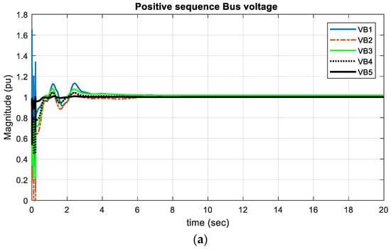
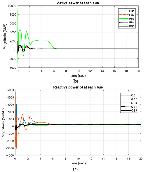
Figure 9.
Simulation results of positive sequence voltage (a), active (b) and reactive power (c) with ALO.
The positive sequence voltages, active power and reactive power at different buses will be obtained, as shown in Figure 9a–c. Although there were oscillations for a few seconds, the system returned to its steady state. The time required for the damping power system oscillations is reduced when PSS is installed in the system; the system is stabilized in a short duration of time.
4.3. Comparison of Proposed Optimization Technique with Other Techniques
The simulation result clearly illustrates that the proposed objective function-based optimized PSS2B has good performance in damping LFO and stabilizes the system quickly compared to the conventional fixed-gain model, GA, PSO and TLBO methods. The comparison analysis on the impact of different techniques for optimal sizing of PSS parameters has been illustrated in Figure 10, Figure 11 and Figure 12 below. A detailed explanation of the maximum overshoot and settling time of different algorithms is presented in Table 9 below. Table 9 clearly shows the tabular representation of power system states, which are depicted in Figure 10, Figure 11 and Figure 12.
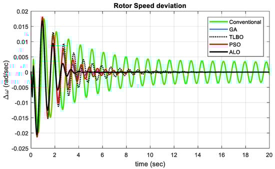
Figure 10.
Rotor speed deviation of different algorithms with conventional fixed gain.

Figure 11.
Rotor angle deviation of different algorithms with conventional fixed gain.
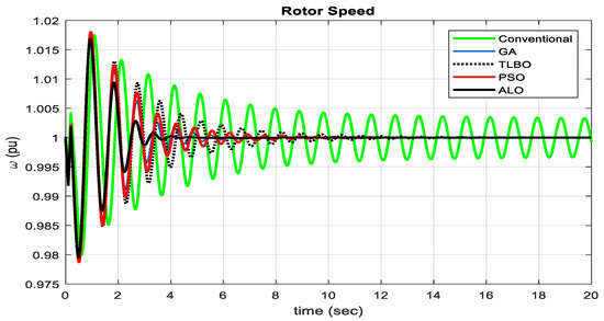
Figure 12.
Rotor speed of different algorithms with the conventional fixed gain model.
Table 9.
Maximum overshoot and settling time of power system parameters.
From Figure 10 above, it is apparent that the rotor speed deviation of different algorithms with conventional fixed gain and the maximum overshoot and settling time of ALO is less than for the other optimization algorithms. Generally, the ALO technique gives more accurate results than the rest of the techniques for damping out low-frequency oscillation within the shortest possible time. The simulation result demonstrated that the ALO technique is the most effective for solving and damping out of the LFO problem as the maximum overshoot and settling time of angular frequency deviations are relatively small compared to other techniques. The obtained results are promising and prove the potential of the proposed LFO control strategy-based ALO algorithm to ensure power system stability.
From Figure 11 above, it is apparent that the rotor angle deviation of different algorithms with conventional fixed gain model and the maximum overshoot and settling time of ALO is less than the remaining techniques. ALO gives more accurate results than the rest of the methods to damp out low-frequency oscillation within the shortest possible time.
From the simulation results shown in Figure 12 above, the rotor speed of different algorithms and the maximum overshoot and settling time of ALO is less than the remaining techniques, and, generally, ALO gives more accurate results when compared to the other techniques for damping out low-frequency oscillation within the shortest possible time.
The proposed ALO has good performance and gives better results in terms of minimizing the fluctuations of low-frequency oscillations and shows superiority compared with conventional fixed gain, GA, PSO and TLBO approaches. The comparative study shows that the ALO algorithm could rapidly converge to the correct optimal solution and gives the optimal sizes of POD controller parameters.
4.4. Simulation Results at Different Operating Conditions
For a power system, the operating load can vary over a wide range. It is necessary to test the variations in operating conditions for the power system. It is clear that the proposed PSS2B approach can significantly damp out the unwanted LFO and improve the stability performance of the Tana Beles 400 kV transmission network. The three operating conditions, normal, light and heavy loading, have been used for comparison purposes.
4.4.1. Simulation Result at Normal Operating Condition
The robustness of the proposed method is tested with the test system under nominal loading conditions. Figure 13, Figure 14, Figure 15, Figure 16 and Figure 17 show the parameters determined under nominal operating conditions of the system. From these results, the system is not properly damped with the existing conventional system. Whereas the PSS2B shows a good damping effect on low-frequency oscillations when compared with no controllers. The settling time and maximum overshoot of these oscillations are also good for the system.
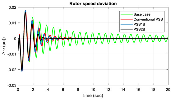
Figure 13.
Rotor speed deviation () of the power system at normal loading.
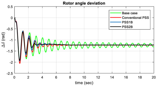
Figure 14.
Rotor angle deviation () of the power system at normal loading condition.
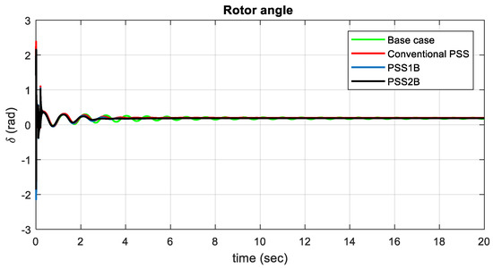
Figure 15.
Rotor angle () of the power system at normal loading.
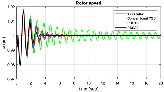
Figure 16.
Rotor speed () of the power system at normal loading.
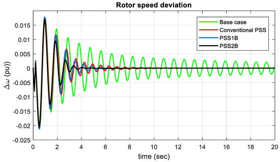
Figure 17.
Rotor speed deviation of the power system at heavy loading.
For normal operating condition Table 10 shows the maximum overshoot and settling time of rotor speed deviation.
Table 10.
Maximum overshoot and settling time of rotor speed deviation at normal loading.
From Figure 13, the rotor speed deviation of the generator has been demonstrated with the existing system and PSS2B at nominal loading conditions. Due to a small disturbance of turbine rotor speed oscillation, the settling time is 20 and 4.614 s for conventional and PSS2B, respectively, which quickly damp out oscillations and return to a steady-state system. Therefore, the generator rotor speed oscillations for PSS2B show increased damping compared to the existing conventional system. Therefore, with the conventional model, the system is oscillatory and becomes unstable, while the stability of the system is maintained, and low-frequency oscillations are effectively damped with PSS2B.
For normal operating condition Table 11 shows the maximum overshoot and settling time of rotor angle deviation.
Table 11.
Maximum overshoot and settling time of rotor angle deviation at normal loading.
Rotor angle deviation with the conventional base case is an oscillatory system and takes a long time to damp out those oscillations and attain a steady-state operation, while when PSS2B is used, the system damps out and diminishes the oscillations very quickly. Therefore, using PSS2B can quickly damp out electromechanical oscillations. When rotor angle deviation is subjected to a positive change , the power will be subjected to and the machine falls towards the instability. When a deviation of occurs, the machine returns to its initial state. For normal operating deviation Table 12 shows the maximum overshoot and settling time of rotor angle.
Table 12.
Maximum overshoot and settling time of rotor angle at normal loading.
The initial generator rotor angle () is around 2.1298 and 2.155 rad for the existing conventional system and PSS2B, and the settling time is 20 and 2.91 s, respectively. According to the IEEE standards for rotor angle stability, the obtained graphs show that the generator oscillates and attains steady-state values. Since δ starts to decrease after reaching a maximum value, the machine returns to its steady state. For normal operating condition Table 13 shows the maximum overshoot and settling time of rotor speed.
Table 13.
Maximum overshoot and settling time of rotor speed at normal loading.
Figure 16 shows the generator rotor speed () of the base case and PSS2B, and a step increase in load is taken as a disturbance, which shows the per-unit speed of the Tana Beles generator. The standard rated speed of the generator is expected to be between 0.95 and 1.05 pu when the synchronous machine is healthy. The rotor speed oscillations of the generator with the conventional controller take approximately 20 s to damp out, and when PSS2B is included, it takes around 4.49 s to damp out and come to a steady-state system. The rotor speed oscillations with PSS2B show increased damping compared to the existing conventional system.
4.4.2. Discussion of Results at Normal Operating Conditions
Generally, at normal loading conditions, the simulation results show that the proposed PSS2B gives good damping characteristics for LFO. When compared with the base case system, PSS2B quickly stabilizes the system under a sudden load increase in the system. Hence, it can be concluded that the proper sizing of PSS parameters using the ALO approach provides effective damping characteristics for the damping out of LFO.
4.4.3. Simulation Result at Heavy Operating Conditions
To check the effectiveness of the proposed controller, the system is operated under heavy operating conditions. Figure 17, Figure 18, Figure 19, Figure 20, Figure 21 and Figure 22 represent the simulation results of the system under a heavy loading condition. From the results of the test system, the existing conventional system is unstable, and the generator loses its synchronism.
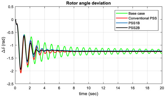
Figure 18.
Rotor angle deviation of the power system at heavy loading.
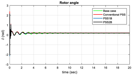
Figure 19.
Generator rotor angle of the power system at heavy loading.
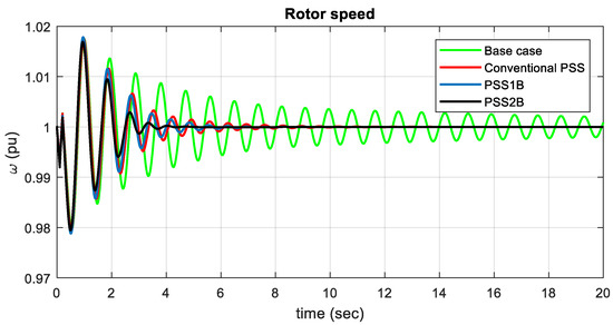
Figure 20.
Generator rotor speed () of the power system at heavy loading.
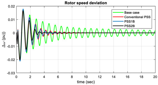
Figure 21.
Rotor speed deviation of the power system at light loading.
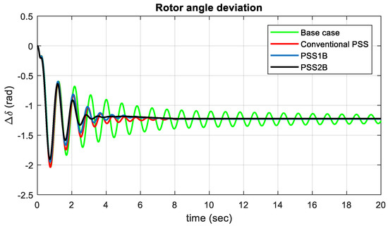
Figure 22.
Rotor angle deviation of the power system at light loading.
For heavy operating condition Table 14 shows the maximum overshoot and settling time of rotor speed deviation.
Table 14.
Maximum overshoot and settling time of rotor speed deviation at heavy loading.
A step increase in load is taken as a disturbance in the heavy loading condition. In Figure 17, the rotor speed deviation of the generator has been demonstrated for the base case, conventional PSS, PSS1B and PSS2B under heavy loading conditions. Due to small disturbances of turbine rotor speed, the oscillation overshoot varies at 0.01748, 0.01747, 0.01738 and 0.0167 with a settling time of 20, 10.35, 6.98 and 4.77 s, respectively. Therefore, the generator’s rotor speed oscillations with PSS2B show increased damping compared to the existing conventional system under a heavy loading condition. For heavy operating condition Table 15 shows the maximum overshoot and settling time of rotor angle deviation.
Table 15.
Maximum overshoot and settling time of rotor angle deviation at heavy loading.
A step increase in load is taken as a disturbance in the heavy loading condition. The rotor angle deviation of the existing conventional system is an oscillatory system and takes a long time to damp out the low-frequency oscillations and attain a steady-state operation, while when PSS2B is incorporated, the system damps out and diminishes the oscillations very quickly. Therefore, by using PSS2B, it can damp out electromechanical oscillations or low-frequency oscillations. When the rotor angle deviation is subjected to a positive change then the power will be subjected to , and the machine falls towards instability. When a deviation of occurs, the machine attains its initial state. For heavy operating condition Table 16 shows the maximum overshoot and settling time of rotor angle.
Table 16.
Maximum overshoot and settling time of rotor angle at heavy loading.
A step increase in load is taken as a disturbance in the heavy loading condition. According to the IEEE standards of rotor angle stability, the obtained graphs show that the generator oscillates and attains steady-state values. Therefore, the generator fulfills the local mode and inter-area mode of oscillation, having a 2.75 s settling time and around 2.0259, 2.1729, 2.150 and 2.144 rad for the base case, conventional PSS, PSS1B and PSS2B, respectively. Since δ starts to decrease after reaching a maximum value, the machine attains its steady-state value. For heavy operating condition Table 17 shows the maximum overshoot and settling time of rotor speed.
Table 17.
Maximum overshoot and settling time of rotor speed at heavy loading.
Figure 20 shows the generator rotor speed () for the base case and PSS2B, a step increase in the load is taken as a disturbance, which shows the per-unit speed of the Tana Beles generator. The rotor speed oscillations of the generator for the conventional base case take greater than 20 s to damp out oscillations, and when PSS2B is included, it takes around 4.67 s. The standard rated speed of the generator is expected to be between 0.95 and 1.05 pu when the synchronous machine is healthy. The addition of PSS2B improved the damping of the generator rotor speed oscillations by quickly damping out oscillations and attaining the steady-state system.
4.4.4. Discussion of Results at Heavy Operating Conditions
Generally, the simulation results show that at heavy loading conditions, the proposed PSS2B gives effective damping characteristics to LFO that rapidly stabilizes the system under disturbance when compared with the conventional base case. From the above study with the SMIB system connected to PSS2B, it is concluded that it can effectively damp out the low-frequency oscillations by using PSS2B and hence, the stability of the system increases.
4.4.5. Simulation Result at Lightly Loading Condition
The figure shown below represents the simulation results of the system at the lightly loading condition. The low-frequency oscillation is damped out rapidly with the proposed optimized controller compared with the conventional base case. For light operating condition Table 18 shows the maximum overshoot and settling time of rotor speed deviation.
Table 18.
Maximum overshoot and settling time of rotor speed deviation at light loading.
In Figure 21, the rotor speed deviation () of the generator is demonstrated for the conventional base case and PSS2B under lightly loading conditions. Therefore, the generator rotor speed oscillations with PSS2B show increased damping compared to the existing conventional system under lightly loading conditions. Therefore, for the conventional fixed-gain model, the system is oscillatory and becomes unstable, while the stability of the system is maintained with the proposed PSS2B. For light operating condition Table 19 shows the maximum overshoot and settling time of rotor angle deviation.
Table 19.
Maximum overshoot and settling time of rotor angle deviation at light loading.
At lightly loaded conditions, the rotor angle deviation of the existing conventional system is an oscillatory system and takes a long time to damp out the oscillations, while when PSS2B is used, the system damps out and diminishes the oscillations quickly. Therefore, using PSS2B can quickly damp out electromechanical oscillations. When the rotor angle deviation is subjected to a positive change the power will subjected to and the machine falls towards instability. When a deviation of occurs, the machine returns to its initial state. For light operating condition Figure 23 shows the maximum overshoot and settling time of rotor angle.
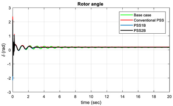
Figure 23.
Rotor angle of the power system at light loading.
For light operating condition Table 20 shows the maximum overshoot and settling time of rotor angle.
Table 20.
Maximum overshoot and settling time of rotor angle at light loading.
The initial generator rotor angle () is around 2.0063, 2.1513, 2.128 and 2.125 rad for the base case, conventional PSS, PSS1B and PSS2B, respectively. According to the IEEE standards of rotor angle stability, the obtained graphs show that the generator oscillates and attains steady-state values. Therefore, the generator fulfills the local mode of oscillation and inter-area mode of oscillation, having a 2.8 s settling time. The time taken to damp out low-frequency oscillation is 2.8 s for PSS2B. Since δ starts to decrease after reaching a maximum value, the machine attains its steady state. For light operating condition Table 21 shows the maximum overshoot and settling time of rotor speed.
Table 21.
Maximum overshoot and settling time of rotor speed at light loading.
Figure 24 shows the generator rotor speed for the existing conventional system and PSS2B under lightly loaded conditions. A sudden load change is taken as a disturbance, which shows the per-unit speed of the Tana Beles generator. The standard rated speed of the generator is expected to be between 0.95 and 1.05 pu when the synchronous machine is healthy. The rotor speed oscillations of the generator for the existing conventional system take approximately 20 s to damp out, and when PSS2B is included, it takes around 4.43 s to quickly damp out the oscillations and return to a steady-state system.
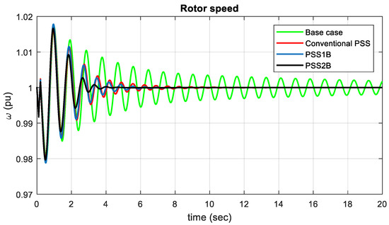
Figure 24.
Rotor speed of power system at light loading.
4.4.6. Discussion of Result at Lightly Operating Condition
Generally, for lightly loading operating conditions, the simulation result shows that the proposed PSS2B provides effective damping for LFO and stabilizes quickly when compared with the existing conventional system. Hence, it can be concluded that the system with fine sizing of the PSS parameters provides robustness for the controller, and it attains power system stability rapidly. The system can effectively damp out the low-frequency oscillations by using PSS2B; hence the stability of the system is maintained.
4.5. Main Achievements of the Proposed Method
The proposed dual-input power system stabilizer is superior to the conventional power system stabilizer. As the results of eigenvalue analysis show that with the conventional PSS, the system is not stable due to poorly tuned controller parameters. With the conventional power system stabilizer, the controller gain and time constants were not properly tuned, and the results show that the system is not stable. Since the power system is a dynamic, conventional PSS, it does not vary its operating conditions and looks static as a result. To test the robustness of the proposed method, different operating conditions were considered for both eigenvalue analysis and time-domain simulation results. Ref. [16] shows that PSS is designed for more complex systems, but the parameters of PSS are not properly tuned to make the system stable. In [17], genetic algorithm utilized for the coordination of PSSs and UPFC. Similarly robust PSSs are proposed using GA in [18]. For this case, the eigenvalue-based multi-objective function is formulated as a damping factor and damping ratio. The low controller gain, time constant, computational time, convergence curve, maximum overshoot and settling time shows that the proposed PSS2B design is superior to GA and the other applied methods.
5. Conclusions
In this paper, low-frequency oscillation damping using a PSS2B controller was studied. This paper examined the efficiency of meta-heuristic techniques called ALO for the damping of low-frequency oscillations in an electric network by optimally sizing the PSS parameters. This technique has been selected by critically reviewing and comparing it with the base case. The proposed system is used to estimate the key parameters in real-time depending on the operating conditions. The superiority of the proposed ALO system over the conventional fixed-gain model was confirmed through the presented simulation results of rotor angle deviation, rotor speed deviation, rotor angle and rotor speed. The controller gain of the proposed technique is lower, which shows that the amplification of the noise signal will be reduced. Furthermore, the proposed technique requires a very short time (about 15 s) to predict the parameters of the objective functions provided. Therefore, the proposed ALO-based dual-input power system stabilizer is superior to the other applied techniques for a complex power system.
Author Contributions
Conceptualization, E.S.B. and B.K.; methodology, E.S.B., Z.M.A. (Zaid M. Ali) and Z.M.A. (Zuhair Muhammed Alaas); software, E.S.B. and B.K.; validation, E.S.B., B.K. and O.P.M.; formal analysis, E.S.B. and B.K.; investigation, E.S.B. and B.K.; resources, E.S.B. and B.K.; data curation, B.K., E.S.B., O.P.M. and Z.M.A. (Zaid M. Ali); writing—original draft preparation, E.S.B. and B.K.; writing—review and editing, E.S.B., B.K., O.P.M. and Z.M.A. (Zuhair Muhammed Alaas), visualization, B.K.; supervision, B.K.; project administration, B.K.; funding acquisition, Z.M.A. (Zaid M. Ali). All authors have read and agreed to the published version of the manuscript.
Funding
This research received no external funding.
Institutional Review Board Statement
Not applicable.
Informed Consent Statement
Not applicable.
Data Availability Statement
All the data are obtained from Ethiopian electric power and Tana Beles generation station.
Conflicts of Interest
The authors declare that there is no conflict of interest of any author in any form.
Nomenclature
| Hz | Hertz |
| IT | Current iteration |
| Maximum number of iterations | |
| Pu | Per unit |
| M, D | Inertia Constant, Damping Coefficient |
| Synchronous Speed of the Generator | |
| δ, ω | Rotor Angle, Rotor Speed |
| Generator Internal Voltage | |
| Field Voltage | |
| AC Bus Reference Voltage | |
| Control Signal of PSS | |
| Id, Iq | dq axes Generator Armature Current |
| Vt | Generator Terminal Voltage |
| KA, TA | Gain and Time Constant of Exciter and Regulator |
| Vb | Infinite Bus Voltage |
| Eigenvalues | |
| σi, ωi | Eigenvalue’s Real Part and Imaginary Part |
| ζ | Damping ratio of mth Eigenvalue |
| T1, T2, T3, T4 | Time Constants |
| K, Tw | Controller Gain and Washout Time Constant |
| Stabilized Voltage | |
| Abbreviations | |
| AC | Alternating current |
| AL | Antlion |
| ALO | Antlion optimization |
| AVR | Automatic voltage regulator |
| DC | Direct current |
| EEP | Ethiopian Electric power |
| FLC | Fuzzy logic controller |
| FLPSS | Fuzzy logic power system stabilizer |
| GA | Genetic Algorithm |
| IEEE | Institute of Electrical and Electronics Engineers |
| kV | Kilo volt |
| kVA | Kilo Volt Ampere |
| kVAr | Kilo Volt Ampere reactive |
| LFO | Lows frequency oscillation |
| MATLAB | Matrix Laboratory |
| MVA | Mega Volt Ampere |
| MVAr | Mega Volt Ampere reactive |
| MW | Mega watt |
| MWh | Megawatt hour |
| NP | Number of operating point |
| PSS | Power system stabilizer |
| PSO | Particle swarm optimization |
| POD | Power oscillation Damper |
| RC | Resistor Capacitor |
| RWs | Random walks |
| SFLA | Shuffled frog leaping algorithm |
| SMIB | Single machine infinite bus system |
| TLBO | Teaching learning-based optimization |
Appendix A
Tana Beles HPP all data.
| Generator parameters of the system | M = 8 MJ/MVA D = 4 |
| Exciter type EXST1 data | , |
| Control parameters for generators with governor type UYGOV | |
| Transformer | |
| Transmission line | |
| Operating condition |
Existing Generator data of Tana Beles.
| No. | Name | Sn (MVA) | V (kV) | P (MW) | Pmin (MW) | Pmax (MW) | Qmin (MVAR) | Qmin (MVAR) |
| 1 | Beles G1 | 133 | 15 | 80 | 0 | 115 | −130 | 130 |
| 2 | Beles G2 | 133 | 15 | 100 | 0 | 115 | −130 | 130 |
| 3 | Beles G3 | 133 | 15 | 90 | 0 | 115 | −130 | 130 |
| 4 | Beles G4 | 133 | 15 | 100 | 0 | 115 | −130 | 130 |
Load buses:
Transmission line parameters in pu from Tana Beles 400 kV to Bahir Dar.
| No. | From Bus | To Bus | R (pu) | X (pu) | B (pu) | KA | Km |
| 1 | Tana Beles 400 | Bahir Dar 400 | 0.000958 | 0.012159 | 0.37713 | 1341 | 65 |
Transformer parameters
| Voltage (kV) | Rating (MVA) | R (%) | X (%) | X/R Ratio |
| 400/230 | 133 | 0.176 | 12.045 | 68.44 |
| 400/15 | 133 | 0.215 | 13.5 | 62.79 |
References
- Grebe, E.; Kabouris, J.; Barba, S.L.; Sattinger, W.; Winter, W. Low frequency oscillations in the interconnected system of Continental Europe. In Proceedings of the IEEE PES General Meeting, Minneapolis, MN, USA, 25–29 July 2010; pp. 1–7. [Google Scholar]
- Al-Hinai, A.S.; Al-Hinai, S.M. Dynamic stability enhancement using particle swarm optimization power system stabilizer. In Proceedings of the 2009 2nd International Conference on Adaptive Science & Technology (ICAST), Accra, Ghana, 14–16 January 2009; pp. 117–119. [Google Scholar] [CrossRef]
- Datta, S.; Roy, A.K. Fuzzy logic based STATCOM controller for enhancement of power system dynamic stability. In Proceedings of the International Conference on Electrical & Computer Engineering (ICECE 2010), Dhaka, Bangladesh, 18–20 December 2010; pp. 294–297. [Google Scholar] [CrossRef]
- Rout, K.C.; Panda, P.C. An adaptive fuzzy logic based power system stabilizer for enhancement of power system stability. In Proceedings of the 2010 International Conference on Industrial Electronics, Control and Robotics, Rourkela, India, 27–29 December 2010; pp. 175–179. [Google Scholar] [CrossRef]
- Haghshenas, M.; Hajibabaee, M.; Ebadian, M. Controller Design of STATCOM Using Modified Shuffled Frog Leaping Algorithm for Damping of Power System Low Frequency Oscillations. Int. J. Mechatron. Electr. Comput. Technol. 2016, 6, 2786–2799. [Google Scholar]
- Luo, J.; Bu, S.; Teng, F. An optimal modal coordination strategy based on modal superposition theory to mitigate low frequency oscillation in FCWG penetrated power systems. Int. J. Electr. Power Energy Syst. 2020, 120, 105975. [Google Scholar] [CrossRef]
- Sengupta, A.; Das, D.K. Mitigating inter-area oscillation of an interconnected power system considering time-varying delay and actuator saturation. Sustain. Energy Grids Netw. 2021, 27, 100484. [Google Scholar] [CrossRef]
- Rahman, M.; Ahmed, A.; Galib, M.H.; Moniruzzaman. Optimal damping for generalized unified power flow controller equipped single machine infinite bus system for addressing low frequency oscillation. ISA Trans. 2021, 116, 97–112. [Google Scholar] [CrossRef] [PubMed]
- Trevisan, A.S.; Fecteau, M.; Mendonça, Â.; Gagnon, R.; Mahseredjian, J. Analysis of low frequency interactions of DFIG wind turbine systems in series compensated grids. Electr. Power Syst. Res. 2021, 191, 106845. [Google Scholar] [CrossRef]
- Darabian, M.; Bagheri, A. Design of adaptive wide-area damping controller based on delay scheduling for improving small-signal oscillations. Int. J. Electr. Power Energy Syst. 2021, 133, 107224. [Google Scholar] [CrossRef]
- Mirjalili, S. The Ant Lion Optimizer. Adv. Eng. Softw. 2015, 83, 80–98. [Google Scholar] [CrossRef]
- Thu, W.M.; Lin, K.M. Mitigation of Low Frequency Oscillations by Optimal Allocation of Power System Stabilizers: Case Study on MEPE Test System. Energy Power Eng. 2018, 10, 333–350. [Google Scholar] [CrossRef][Green Version]
- Khodabakhshian, A.; Hooshmand, R.; Sharifian, R. Power system stability enhancement by designing PSS and SVC parameters coordinately using RCGA. In Proceedings of the 2009 Canadian Conference on Electrical and Computer Engineering, St. John’s, NL, Canada, 3–6 May 2009; pp. 579–582. [Google Scholar] [CrossRef]
- Bomfim, A.D.; Taranto, G.; Falcao, D. Simultaneous tuning of power system damping controllers using genetic algorithms. IEEE Trans. Power Syst. 2000, 15, 163–169. [Google Scholar] [CrossRef]
- Shahriar, M.S.; Shafiullah; Rana, J.; Ali, A.; Ahmed, A.; Rahman, S.M. Neurogenetic approach for real-time damping of low-frequency oscillations in electric networks. Comput. Electr. Eng. 2020, 83, 106600. [Google Scholar] [CrossRef]
- Ajami, A.; Armaghan, M. Application of multi-objective gravitational search algorithm (GSA) for power system stability enhancement by means of STATCOM. Int. Rev. Electr. Eng. 2012, 7, 4954–4962. [Google Scholar]
- Hassan, L.H.; Moghavvemi, M.; Almurib, H.A.; Muttaqi, K.M. A coordinated design of PSSs and UPFC-based stabilizer using genetic algorithm. IEEE Trans. Ind. Appl. 2014, 50, 2957–2966. [Google Scholar] [CrossRef]
- Abdel-Magid, Y.L.; Abido, M.A. Optimal Multi objective Design of Robust Power System Stabilizers Using Genetic Algorithms. IEEE Trans. Power Syst. 2003, 18, 1125–1132. [Google Scholar] [CrossRef]


Publisher’s Note: MDPI stays neutral with regard to jurisdictional claims in published maps and institutional affiliations. |
© 2022 by the authors. Licensee MDPI, Basel, Switzerland. This article is an open access article distributed under the terms and conditions of the Creative Commons Attribution (CC BY) license (https://creativecommons.org/licenses/by/4.0/).