Abstract
Ventilated façade systems are being increasingly used in energy-efficient building envelopes due to their configurational flexibility and potential to reduce thermal bridging. This study focuses on the experimental evaluation of anchoring components used in such systems, specifically examining the effect of various thermal insulation pads and internal inserts on the system’s mechanical, thermal, and fire performance. A series of laboratory tests was carried out to assess the static behavior of aluminum brackets under both tensile (suction wind load) and compressive (pressure wind load) forces. The results demonstrate that the use of thermal pads and inserts does not lead to any significant degradation of the mechanical capacity of the anchoring brackets, confirming their structural reliability. Additional thermal testing revealed that the use of insulating materials significantly reduces heat transfer through the brackets. Fire resistance tests were conducted to compare the performance of different types of insulation pads under elevated temperatures. The findings indicate that the choice of pad material substantially influences both fire integrity and thermal performance. This study confirms the potential of incorporating optimized insulating pads and inserts into façade brackets to enhance the thermal and fire performance of ventilated façades without compromising their structural behavior.
1. Introduction
Ventilated façade systems represent one of the most widely adopted solutions for modern building envelopes. Their popularity derives not only from architectural versatility and esthetic potential, but also from the ability to physically separate the thermal insulation layer from the external cladding. This arrangement improves the hygrothermal performance of the envelope, facilitates moisture removal, and reduces the risk of condensation, which is clearly stated in many publications [1,2,3,4]. In both new construction and renovation projects, ventilated façades have therefore become closely associated with sustainable and energy-efficient building practices. A crucial component of these systems is the substructure, typically consisting of metallic brackets and profiles that connect the cladding panels to the primary structural wall. Aluminum brackets are among the most widely used and standard solutions for ventilated façade anchoring systems, primarily due to their favorable strength-to-weight ratio, corrosion resistance, and ease of installation. These advantages make them a preferred choice in common construction practice. At the same time, from the perspective of mechanical resistance, aluminum brackets represent one of the least resistant type of bracket, which makes their behavior under loading particularly important to investigate [5,6,7]. In service, they are subjected to a combination of self-weight, variable wind actions, and thermal expansion. Thus, their mechanical stability and long-term resistance determine the overall reliability of the façade assembly. In the ongoing effort to improve the thermal performance of ventilated façades, the thickness of the applied thermal insulation is continuously being increased. This trend leads to greater eccentricity and higher mechanical demands on façade brackets, resulting in increased requirements for their dimensions and load-bearing capacity. Moreover, the incorporation of insulating inserts and pads into the brackets, intended to reduce thermal bridges, further amplifies the challenge of mechanical resistance, as these elements may adversely affect the stiffness and overall structural performance of the anchoring system [1].
The major drawback of metallic brackets (not only aluminum ones) lies in their high thermal conductivity. If not mitigated, this property interrupts the continuity of the insulation and generates pronounced point thermal bridges, significantly reducing the effective thermal resistance of the façade [8]. Numerical analyses and experimental studies have demonstrated that overlooking these effects can lead to a considerable underestimation of heat losses [1,2]. To reduce heat transfer through the bracket, it is advisable to use insulating pads under the bracket base or to replace part of or the whole aluminum bracket with a suitable plastic, thermally insulating material. Experimental and numerical analyses confirmed that the modified polyamide–aluminum brackets can achieve a high loading capacity, full material bonding, and improved thermal and acoustic performance for curtain wall applications [5]. The study demonstrated that replacing aluminum façade subframes with pultruded glass-fiber-reinforced polymer (GFRP) elements significantly reduces thermal bridging, achieving 7–13% heating energy savings while maintaining structural strength and durability [9]. In the context of the increasingly stringent energy efficiency requirements, this issue has become highly relevant.
A common mitigation strategy involves the use of insulating pads or inserts positioned at the interface between the bracket and the wall [10,11,12]. These components, manufactured from fiber-reinforced plastics, glass-filled polyamides, or high-temperature composites, provide reduced thermal conductivity compared to aluminum [2,13]. However, the introduction of these elements raises concerns regarding the mechanical behavior of the connection. Their stiffness and strength are substantially lower than those of aluminum, which may influence local stress distribution, effective load transfer, and the overall load-bearing capacity [8,14,15].
The increase in heat flow through a wall caused by local elements is described by the point thermal transmittance χ [W/K]. Only by accounting for these local effects, expressed in the form of an additional term ΔU, can the objectively correct value of the wall thermal transmittance (U-value) [W/(m2·K)] of the entire construction assembly be determined. However, the quantification of point thermal transmittance χ [W/K] is challenging and its influence is often underestimated in practice [2,12,16].
One study [7] reported point thermal transmittance values for a ventilated façade anchoring system made of aluminum (λ = 230 W/(m·K)) and, subsequently, of a polymeric composite (λ = 0.055 W/(m·K)), considering both the bracket and the vertical profile. The author investigated the same type of anchoring system considered in the present study, which is schematically illustrated in Figure 1. For systems with aluminum brackets and profiles, a point thermal transmittance of χ = 0.051 W/K has been reported. While replacing the material of the vertical profile resulted in only a moderate improvement to χ = 0.030 W/K, replacing the bracket material led to a significant reduction to χ = 0.004 W/K, i.e., nearly one order of magnitude. When both elements were made of polymeric composite, the value further decreased to χ = 0.003 W/K, representing only a marginal additional improvement. These results clearly indicate that the bracket is the critical element governing thermal bridging and therefore requires the most attention.
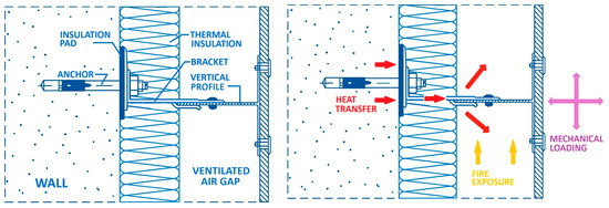
Figure 1.
Floor plan (horizontal section) of ventilated façade with anchoring elements: anchor, bracket, and vertical profile. Schematic illustration of the investigated phenomena: fire exposure, heat transfer, and mechanical loading.
A comprehensive analysis addressing not only the influence of the anchoring element but also the effects of the thermal conductivity of the load-bearing wall and the bracket size is reported in [14]. For aluminum brackets, the reported point thermal transmittance χ ranged from 0.04 W/K to 0.11 W/K, increasing with higher thermal conductivity of the wall material. The point thermal transmittance χ also increased with the thickness of the thermal insulation layer: for a thermal insulation thickness of 0.05 m, χ = 0.061 W/K, whereas for 0.30 m, χ = 0.068 W/K.
A similar issue is addressed in [10], which focuses on the influence of bracket material. Experimental and theoretical investigations were carried out for a thermal insulation layer thickness of 300 mm made of expanded polystyrene (λ = 0.031 W/(m·K)). The insulation layer was penetrated by L-shaped connectors made of aluminum alloy (λ = 160 W/(m·K)), stainless steel (λ = 17 W/(m·K)), and glass-fiber-reinforced plastic (λ = 0.23 W/(m·K)). The results of heat transmittance calculations and measurements obtained using three different methods showed that the accuracy of commonly used empirical methods is limited when applied to brackets with high thermal conductivity, particularly aluminum connectors. As stated by the authors, “For this reason, there is a need to carry out more comparative calculations and experimental measurements with various materials and thicknesses of thermal insulation and different kinds of connectors to analyze heat transfer from the connector to the thermal insulation material”.
By comparing multiple evaluation methods, it was found that replacing aluminum brackets with stainless steel reduces the point thermal transmittance χ from 0.040 W/K to 0.007 W/K. The bracket material therefore has a slightly greater influence on thermal bridging than the application of insulating pads. Nevertheless, insulating pads represent a more cost-effective mitigation measure and are therefore given further attention in this study.
Fire resistance represents another critical aspect. In high-rise buildings and other constructions subject to strict fire safety regulations, the performance of insulating pads must meet defined classifications and stability criteria. Investigations have shown that different insulating materials display significant variation in fire resistance, which has implications for façade safety under elevated temperatures [8]. Large-scale studies further demonstrated that the presence or absence of additional fire-protective layers can affect flame spread and façade integrity [17,18,19].
Given these interrelated aspects, further research is necessary to systematically evaluate the thermal, mechanical, and fire performance of ventilated façade substructures [9]. The present study addresses this need by experimentally examining selected insulating pads and inserts used with aluminum and other brackets. The test program focuses on the fire resistance of insulating materials under controlled heating conditions and the static load-bearing behavior of aluminum brackets with and without insulating layers. The objective is not to demonstrate structural improvement, but rather to confirm that the integration of thermal break components does not significantly reduce the stiffness or load capacity. The results are intended to contribute to the ongoing discussion on the optimal balance between energy efficiency, fire safety, and structural reliability in ventilated façade design.
2. Experimental Program
The experimental program was designed to evaluate the performance of aluminum and other brackets used in ventilated façade systems when combined with thermal break pads.
Three main types of tests were conducted:
- Mechanical tests of the façade brackets under static loading;
- Fire resistance tests of selected insulating pads;
- Thermal transmission (heat flux) measurements across bracket–insulation assemblies.
The objective was to assess both the structural safety and thermal efficiency of configurations commonly used in ventilated façades.
Brackets are manufactured from various metals, while polymer-based materials are exclusively used for the insulating pads. Differences in the mechanical properties of metallic materials result in variations in bracket geometry and wall thickness. Aluminum is the most commonly used material, followed by coated carbon steel and stainless steel. The differences between these metals are not limited to mechanical properties, but also include thermal conductivity and the temperature-dependent degradation of mechanical strength and stiffness, which governs their behavior under fire exposure.
In contrast, the insulating pads are made of polymer-based materials, whose behavior at elevated temperatures is characterized by softening, melting, or thermal decomposition. Since the thermal performance of the bracket–wall connection is typically the weakest aspect of the system, it is improved by introducing an insulating pad beneath the bracket or by integrating insulation into the bracket wall.
This approach results in many possible combinations of metallic bracket materials and geometries, together with different polymeric pad materials, configurations, and thicknesses. For the experimental program, only selected characteristic combinations were considered, representing typical, technically relevant, and deliberately extreme cases, including those expected to exhibit the most favorable as well as the least favorable performance. The rationale behind the selection of bracket–pad combinations is discussed in detail for each individual test.
The experimental program therefore does not focus on describing a single structural solution under multiple conditions; instead, it is aimed at addressing critical issues across different façade configurations.
2.1. Mechanical Testing of Brackets
To verify the effect of the applied insulation pads and insulation inserts on the static behavior of anchors, one of the least favorable configurations of a ventilated façade structure was selected.
For reasons of overall economic efficiency (manufacturing, machining, weight, etc.), the most common solution for façade attachment is the use of a simple aluminum bracket. From a structural standpoint, however, this solution usually represents the configuration with the lowest load-bearing capacity. This limitation is caused not only by the material properties (particularly the low modulus of elasticity) but also by load eccentricities. At the same time, the use of aluminum is problematic due to its significant thermal conductivity. The brackets form thermal bridges between the primary structure and the façade surface. This issue has been addressed for some time by using solid insulation pads made of PVC placed beneath the adjacent flange of the aluminum bracket.
The analysis presented in this paper is based on the use of a thick, chamber-type insulation pad with very slender walls, which may be more susceptible to mechanical damage. With regard to material selection, plastics with similar characteristics were considered representative: Tough PLA material for 3D printing was used as the sample material. In addition, the aluminum bracket was equipped with an insulation insert placed in the projecting flange of the aluminum bracket, which may further reduce its mechanical resistance.
The objective of the conducted tests is to verify whether these modifications significantly affect the mechanical resistance of an aluminum bracket without pads and inserts compared to a bracket incorporating the above-mentioned modifications.
In real structures, the aluminum bracket is primarily subjected to wind pressure and wind suction through the attached façade. In some cases, it is also subjected to the weight of the attached façade itself.
In the most common configuration using aluminum brackets, the brackets are arranged in a regular grid. With respect to the transfer of vertical loads (primarily the façade self-weight), the grid consists of so-called fixed brackets and sliding brackets. Fixed brackets are larger, and the façade elements are rigidly connected to them. These brackets are therefore subjected to wind suction and pressure as well as to the vertical force resulting from the façade’s weight. Façade elements are connected to sliding brackets through elongated holes. The sliding brackets only provide support for wind loads and do not transfer vertical loads.
The tests described herein only address the sliding bracket, which is only subjected to wind suction and wind pressure. It should be emphasized that under typical conditions, wind loading is the governing factor, even for fixed brackets. Wind load values are significantly higher than the typical weight of the façade itself.
In common engineering practice, aluminum brackets are designed for selected load values corresponding to standard conditions of use, and for different loading conditions, the grid spacing is adjusted accordingly. An example of such a configuration is shown in Figure 2 along with the whole construction process of the experimental façade.
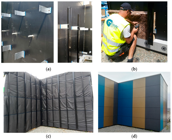
Figure 2.
Construction of experimental block of façade: (a) base wall with a grid of aluminum brackets. The upper row of brackets is built from sliding wind load brackets, while the bottom row are fixed brackets that also carry the weight of façade; (b) installation of thermal insulation; (c) finishing the thermal insulation with a protective layer and a grid of supporting aluminum T-profiles connected to the brackets; (d) finished façade.
The tests were conducted on L-shaped aluminum anchor brackets, whose overall geometry is shown in Figure 3. The bracket was manufactured from AW-6063 aluminum alloy. The protruding flange of the anchor bracket consisted of two separate arms, between which, a 5 mm thick thermal insulation insert made of foamed PVC (FoamLite) was placed. The individual parts were connected through the insert using stainless-steel rivets with a diameter of 4.8 mm.
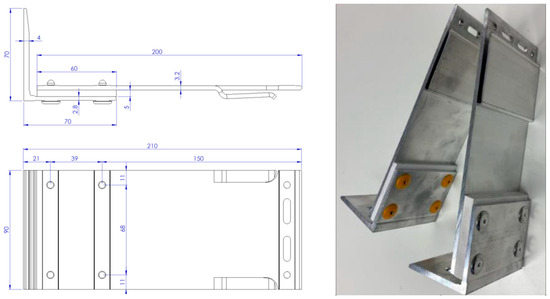
Figure 3.
Geometry of aluminum bracket with an insulation insert.
In the analyzed façade system design, an additional thermal insulation pad included beneath the adjacent flange of the aluminum anchoring bracket was considered. Material options for the insulation pad were studied separately, with a primary focus on fire resistance performance. For mechanical testing purposes, a representative sample of the pad was fabricated using Tough PLA material. The aim of the mechanical tests was to evaluate the overall behavior of the bracket equipped with both the insulation insert and the insulation pad. Both elements exhibit significantly lower strength and deformation characteristics compared to the aluminum bracket itself.
Three bracket configurations were tested:
- Configuration A—anchoring bracket without an insulation pad;
- Configuration B—anchoring bracket with a 5 mm thick insulation pad;
- Configuration C—anchoring bracket with a 19 mm thick insulation pad.
The geometry of the designed pad, along with a reference photograph, is presented in Figure 4.
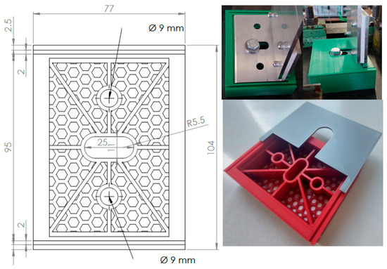
Figure 4.
Geometry of the Tough PLA insulation pad. The thickness was 5 or 19 mm.
Each bracket configuration (with or without insulation pad) was tested under monotonic axial loading using a servo-hydraulic testing machine. A load was applied via a hinge-connected actuator to avoid bending moments. A minimum of two specimens per configuration were tested. Deformations were measured using LVDT sensors with accuracy of ±0.01 mm, and the force was continuously recorded using a calibrated load cell. A summary of the nominal values of the materials’ characteristics is shown in Table 1.

Table 1.
Materials used in mechanical tests.
The bracket was fastened using an M10 bolt (through the hole in the base flange) with a stainless-steel washer and nut. The hole was oval in shape to allow for installation tolerances. For the purpose of the test, the bolt was intentionally positioned as far as possible from the axis of the projecting flange—the most unfavorable position—at a distance of 40 mm from the flange axis. A total of twelve specimens were tested, corresponding to the three configurations described earlier (A, B, and C). Each configuration included four brackets—two subjected to tensile loading and two subjected to compressive loading.
The load was applied under displacement control using a hydraulic actuator equipped with a load cell, which transmits a force through a hinged fixture connected to a T-profile bolted to the end of the projecting flange of the tested bracket (see Figure 5). The displacement rate was 0.05 mm/s. Failure in all cases occurred through plastic deformation of individual parts of the bracket, leading to excessive displacements. The reported results were limited to a maximum applied load of 3.5 kN.
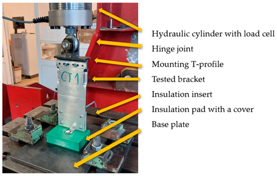
Figure 5.
Axial loading test setup for sliding aluminum bracket (Figure 3) under static tensile and compressive loads.
Results—Comparative Interpretation of Load–Deformation Curves
The graph in Figure 6 summarizes the average results of static loading of angles with tensile and compressive forces.
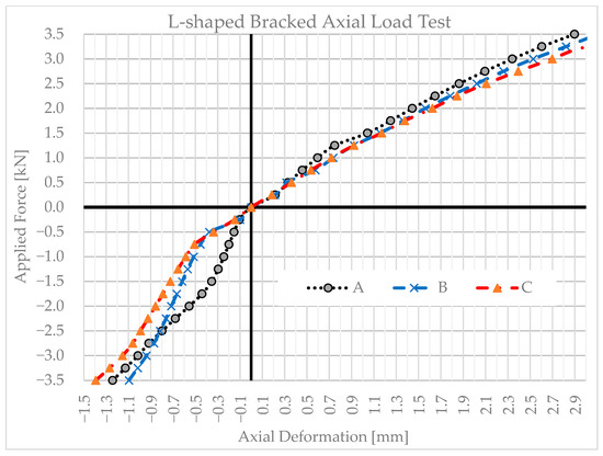
Figure 6.
Axial load deformation diagrams for anchor brackets in configurations A, B, and C.
Appropriate criteria must be selected for the evaluation of the results. Given that this is a composite, geometrically complex system, it is problematic to determine the reliability of the system by directly assessing the ultimate and serviceability limit states with respect to a normal system. For this type of structure, specific deformation limits are not specified in standards, for example, in EN 1999. Establishing reliability would therefore require a larger dataset and statistical evaluation of experimental results; however, this was not the objective of the present study.
Consequently, the comparison of results was solely based on the trends in the load–displacement curves and the secant modulus of elasticity.
Two samples of insulation pads after testing are shown in Figure 7. Plastic deformation of the reinforcing ribs of the pads is evident, especially during the tensile test. However, this corresponds to extreme deformation of the aluminum bracket.
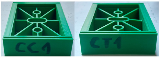
Figure 7.
Sample C with 19 mm insulating pad after compression (CC1) and tension test (CT1).
Tension load: Under tension loads of 0 to 3.5 kN, the three configurations behaved similarly in terms of shape and ultimate force. The only difference was initial stiffness: the reference (A, no pad) was marginally stiffer, B (5 mm pad) was slightly softer, and C (19 mm pad) was slightly softer than B. This is consistent with the pads’ lower modulus and added compliance when in series with a bracket–wall interface. Within the measurement range, the reduction in secant stiffness was modest (visually apparent but not large (5–10%)), and there was no indication that the pads reduced the force in the tested range. This supports the design premise that thermal pads do not degrade the tensile resistance of the bracket assembly; they only introduce a minor elastic compliance.
Compression load: The global capacities up to 3.5 kN of A, B, and C were comparable, but the padded configurations showed markedly lower stiffness during the early-stage loading (from 0 to –0.5 kN). After this “settling” zone, the curves of B and C converged toward that of A and the slope differences became modest (between −0.5 and −2.0 kN), with C again being slightly softer than B. The pronounced initial softness in B/C is very plausibly due to seating/bedding phenomena rather than true structural weakness.
This could be caused by the following mechanisms:
- Bedding-in of the pad: micro-crushing of surface asperities or local yielding of ribs/cell walls (more evident for the thicker, chambered pad C).
- Interface micro-slip at bracket–pad–substrate contacts until frictional stick is achieved.
- Clearance take-up in the oval fixing hole and under the washer as the bolt bears the full load.
- Localized rotation when the hinged load is introduced non-uniformly increases contact pressure until the bearing area stabilizes.
Design-wise, these are classic start-up effects; they do not point to reduced compressive capacity in the tested range. In practice, these effects can be mitigated through adequate bolt pre-tension during installation (to “seat” the interface before service loading) and by specifying pad geometries/materials that limit local bedding (e.g., denser surface skins or capped cells).
2.2. Fire Resistance Testing of Insulating Pads and the Façade System
The fire tests were aimed at verifying the thermal stability and fundamental behavior of insulation pads placed beneath wall angle brackets exposed to elevated temperatures to simulate the development of a fire in the ventilated cavity. Industrially manufactured pads (polyamide (PA) and solid PVC pads with different thicknesses including 19 mm) and laboratory-prepared/printed variants (pads made from polycarbonate with flame retardants (PC-FR), CPE-CF112 Carbon (a polymer with carbon fibers), PET-G, and PLA/Tough PLA) were tested and compared. The pads were examined both individually in a controlled thermal field and as part of a model build-up of a ventilated façade with various types of anchoring brackets. The aim of the tests was not the standardized classification of complete assemblies, but a comparison of material behavior and the identification of phenomena relevant to the design of the pads.
The properties of the individual plastic materials are summarized in Table 2.
Table 2.
Summary of combustion characteristics of different materials.
Each of the mentioned materials has different chemical compositions, polymer chain structures, additives, and thermo-mechanical properties. These characteristics determine how easily the material ignites, how it burns, and what by-products are generated during combustion.
Polymers containing nitrogen, chlorine, fluorine, or aromatic rings typically exhibit better self-extinguishing properties. In contrast, polymers composed primarily of carbon and hydrogen (such as PLA, PET-G, and PA) burn more easily and cleanly. Materials with a low softening or decomposition temperature deform and drip more rapidly; conversely, a higher decomposition temperature ensures better resistance to ignition.
The thermal and fire resistance of a material is primarily determined by its aromatic structures and the presence of flame retardants. Aromatic structures contain benzene rings (a hexagonal arrangement of carbon atoms with alternating double bonds). These structures are highly stable, resistant to thermal decomposition, and promote the formation of a char layer (carbonaceous crust) during combustion. Flame retardants are chemical additives that reduce the flammability of the material, slow down flame spread, and support the formation of the char layer, thereby preventing the dripping of molten material.
Test program: The tests were carried out in two steps:
- Preparatory temperature tests in a hot-air oven (~20 min/150–220 °C).
- Model test of the build-up in a combustion chamber (~45 min/up to ~900 °C).
Main Results
Preparatory tests: Individual pads (Figure 8) were heated in a hot-air oven with a controlled temperature profile in the range 150–220 °C for approximately 20 min (from 23 to 43 min; Figure 9). Part of each run was performed with a small contact load to simulate initial bedding-in. The temperature profile above/below the specimen was monitored, and, after cooling, visual assessments of shape stability, shrinkage, slumping, collapse of cellular walls and any residual charring were performed.
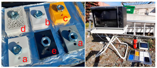
Figure 8.
Samples of weighted pads, electric oven, and measuring and safety equipment. (a) PET-G and (5 and 19 mm), (b) solid PVC (19 mm), (c) PLA (19 mm), (d) PC FR (19 mm), (e) CPE CF112 (5 and 19 mm).
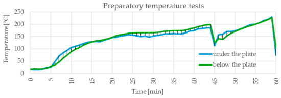
Figure 9.
Temperature profile in the oven during the heat resistance testing of the pads. The test temperature in the range of 150–200 °C was reached between the 23rd and 43rd min.
Within the tested temperature range, there was no combustion or significant smoke generation. Industrial polyamide (PA) pads exhibited the best shape stability; solid PVC (19 mm) showed small to moderate deformations, generally without loss of integrity. PET-G and PLA/Tough PLA displayed softening and slumping, with cellular geometries experiencing collapse of their thin walls. PC-FR and CPE-CF112 usually shrank into a more compact residue without a pasty spread; for CPE-CF112, a more cohesive “rod-like” residue was observed (Figure 10 and Figure 11). At the greatest thickness (19 mm), a loss of stability of the surface “skin” layer was evident, with the core regions remaining relatively stiffer.
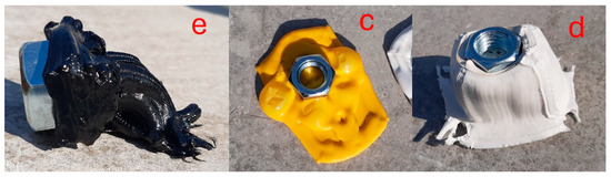
Figure 10.
Spatial deformation of the pads at 220 °C: (c) PLA (19 mm), (d) PC FR (19 mm), and (e) CPE CF112.
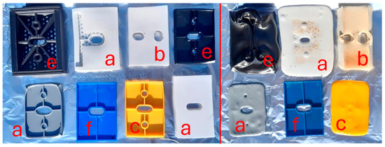
Figure 11.
Pads at temperature of 150 °C (left; 23 min) and 200 °C (right; 43 min): (a) PET-G (5 and 19 mm), (b) solid PVC (19 mm), (c) PLA (19 mm), (e) CPE CF112 (5 and 19 mm), and (f) PA–nylon (5 mm).
Model test (up to~900 °C): A model of a ventilated façade with an area of approximately 1 × 2 m was assembled (cement-bonded particleboard substrate, thermal insulation ~160 mm, vertical profiles, and an array of brackets of various materials), into which the tested pads of representative thicknesses (typically 5/10/19 mm) were inserted. The specimen was placed horizontally over the opening of the combustion chamber (an unfavorable orientation in terms of possible dripping and detachment of softened materials) (Figure 12 and Figure 13). The temperature regime in the chamber was set to ensure that the specimen was exposed to temperatures above 700 °C for at least 40 min, with a peak temperature of nearly 900 °C. The temperature of the insulation pads did not exceed 300 °C (Figure 14). The temperature beneath the bracket toe was monitored at several points; after the test, a visual inspection of the condition of the pads, the brackets, and adjacent layers was carried out.
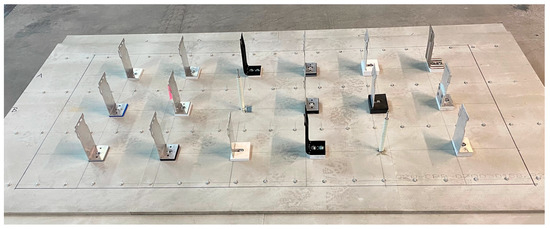
Figure 12.
The model of a ventilated façade with different kinds of brackets (aluminum, steel, and stainless steel, with or without pads) for fire testing.
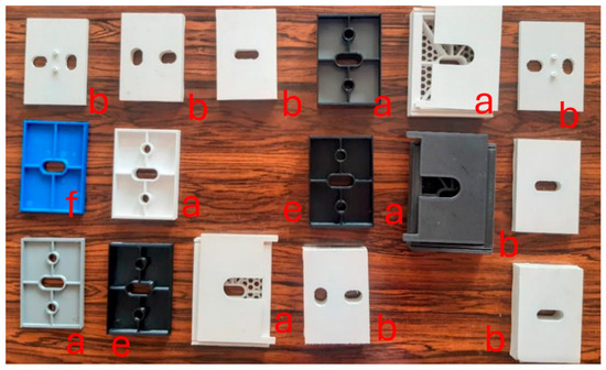
Figure 13.
Different kind of pads (solid and chambered pads made from different materials) used in the model of a ventilated façade for fire testing: (a) PET-G and (5 and 19 mm), (b) solid PVC (19 mm), and (e) CPE CF112 (5 and 19 mm) (f) PA-nylon (5mm).
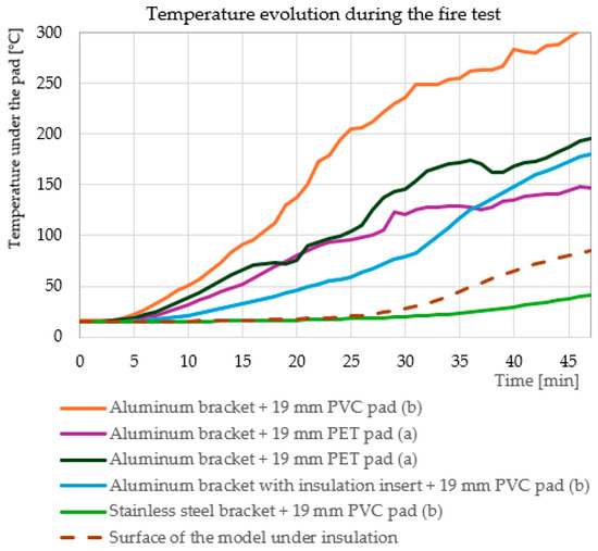
Figure 14.
Temperature of the pads during the fire test. The air temperature in the chamber was maintained in the range of 700–900 °C throughout the test. The smallest temperature increase was observed for the pad beneath the stainless-steel bracket and for the pad beneath the aluminum bracket with inserted insulation.
The thermal conductance Heat-induced deformation within the build-up was strongly dependent on the bracket material, which acts as a point thermal bridge: aluminum (λ ≈ 205–235 W/m·K) conducted heat markedly more than stainless steel (λ ≈ 14–16 W/m·K).
The findings were as follows:
- Industrial PA pads, in combination with stainless-steel brackets, retained good integrity; at higher local heat fluxes (when combined with aluminum brackets), more pronounced changes occurred, typically without slumping into a “puddle”.
- The state of solid PVC (19 mm) was dependent on the adjacent bracket: under stainless-steel brackets, it was undamaged after exposure; under aluminum brackets with an insulation insert, its state was generally at the limit but coherent; and beneath aluminum brackets in regions of higher temperatures, the material transformed into a charred residue.
- In a higher thermal field, PC-FR showed softening and a reduction in wall stability (particularly at greater thicknesses); however, its behavior was more stable than that of PLA/PET-G and less stable than that of PA in the low-temperature phase.
- CPE-CF112 generally maintained compact residues without planar spread. Its higher thermal conductivity compared with common printing plastics could locally influence the temperature distribution, yet its overall integrity was better than that of PLA/PET-G.
- In the higher thermal field, PET-G and PLA/Tough PLA degraded considerably (melting/charring) and practically “disappeared” in the vicinity of aluminum brackets.
At the same time, it was observed that the aluminum components of the assembly (brackets and parts of the profiles) were severely damaged under the described regime; solidified dripping aluminum was visible at the bottom of the chamber (melting point of Al is ~660 °C; Figure 15).
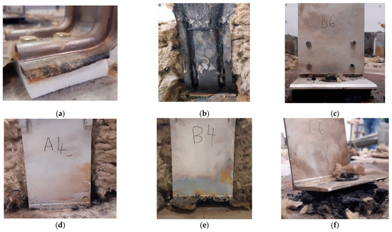
Figure 15.
Damaged brackets and pads after fire test: (a) stainless-steel bracket + 19 mm solid PVC pad; (b) steel bracket + 10 mm solid PVC pad; (c) aluminum bracket with an insulation insert + 19 mm solid PVC pad; (d) aluminum bracket + 19 mm chambered PET pad; (e) aluminum bracket + 19 mm chambered carbon-fiber-reinforced plastic pad; and (f) aluminum bracket + 19 mm solid PVC pad.
Steel and stainless-steel components performed better than the components made from the other materials. Local loss of the binder in the mineral wool in the thermal insulation was evident, with increased air permeability enabling local penetration of hot gases towards the substrate.
Notes on reproducibility and limitations: The model test was conducted with the specimen in a horizontal position, which is unfavorable with regard to dripping and detachment of softened materials; in a vertical orientation, the mechanisms of outflow/degradation would differ. The temperature field in the chamber was not entirely uniform; the mean temperatures beneath the bracket toe varied depending on the bracket material and position relative to the source. The preparatory tests constituted a screening of the low-temperature phase without mechanical loading; standardized classification of the entire build-up was not the aim.
The temperature was increased according to the standard fire curve and surface; internal temperatures were measured using Type K thermocouples inserted at mid-thickness. Post-exposure evaluation included visual inspection, dimensional change measurements, and qualitative assessments of char formation, cracking, or melting.
These tests were intended to identify whether the pads would maintain mechanical function under fire exposure, and whether significant degradation occurred within the initial critical fire period.
2.3. Heat Flux Measurement
To evaluate the influence of insulating pads and bracket modifications, a series of heat transfer measurements through the anchoring system was carried out on a full-scale (1:1) model of a ventilated façade with a representative façade build-up (Figure 16). The heat flow through the anchoring elements is governed by the combined thermal resistance of the load-bearing wall, the bracket material and geometry, and the insulating pad.
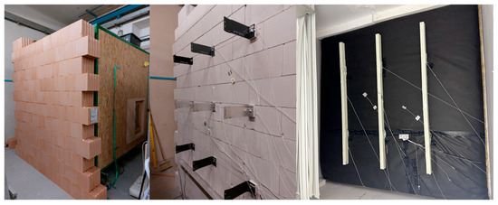
Figure 16.
View of the ventilated façade model on the cold side of the climatic chamber.
For this reason, two sets of tests were performed using different wall substrates: a ceramic masonry wall and a calcium silicate masonry wall. Various combinations of brackets and insulating pads were applied in order to investigate their mutual interaction and combined effect on thermal performance.
The façade model was installed in a climatic chamber where the temperature difference corresponded to typical environmental conditions. Temperature differences of up to 32 K were achieved, with a stable temperature of 18 °C on the warm interior side and down to −14 °C on the cooled exterior side. After reaching steady-state thermal conditions, temperature data were recorded.
A network of temperature sensors monitored the thermal field both within the wall structure and on the surfaces of the brackets. Several bracket configurations were tested, including variations in geometry and metallic material, the presence or absence of insulating pads, and a newly developed bracket type incorporating an internal insulating layer (Figure 17). The objective of the tests was to identify bracket–pad configurations that achieve the greatest reduction in heat flow compared to a reference configuration consisting of a basic bracket without an insulating pad.
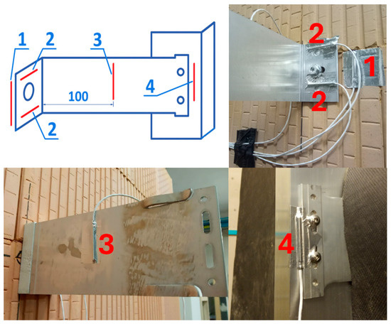
Figure 17.
Temperature sensors on the surface of the bracket and the vertical profile. (1) bearing wall surface, (2) bracket section in contact with the wall, (3) bracket surface at mid-length, (4) vertical profile surface.
Main Results
All bracket–pad combinations were measured under similar conditions, as shown in Table 3, Table 4, Table 5 and Table 6. The average temperature difference across the thermal insulation layer was 25 K, corresponding to nearly 1 K/cm of thickness. While the ceramic wall provides both insulation and greater thickness, the wall made of sand–lime bricks, used as a concrete substitute, is thinner and less thermally insulating. Consequently, brackets on the ceramic wall reached lower temperatures at point 2, which is a favorable outcome. The installation of pads beneath the bracket further reduced the temperature.
Table 3.
Effect of insulating pad thickness and bearing wall material on heat transfer.
Table 4.
The effect of bracket material on heat transfer.
Table 5.
The effect of an insulating layer inserted into the bracket on heat transfer.
Table 6.
The effect of different pad materials on heat transfer.
Table 3 illustrates the significance of insulating pads when applied to walls with lower thermal resistance (sand–lime brick wall) and higher thermal resistance (ceramic brick wall). In the former case, the point thermal bridge associated with the bracket was more pronounced, and the reduction in heat flow achieved by the insulating pad was therefore substantial. In contrast, for walls with superior thermal insulation properties, the contribution of insulating pads was less pronounced.
In both cases, it is evident that increasing the pad thickness from 5 mm to 19 mm enhanced its thermal effectiveness.
Table 4 demonstrates the influence of the bracket material on heat transfer through the anchoring system. Replacing aluminum brackets with steel brackets, particularly with stainless-steel brackets, leads to a significant reduction in heat flow. The newly developed bracket type incorporating an internal insulating layer also exhibited favorable thermal performance, especially when a 10 mm thick insulation insert was used. In terms of heat transfer reduction, this solution is comparable to the use of a solid PVC insulating pad with a thickness of 19 mm.
In addition to insulating pads, thermal insulation can also be integrated directly into the bracket itself, as illustrated in Figure 3. The benefit of this relatively complex structural solution is generally lower than that achieved by insulating pads, as demonstrated in Table 5. In particular, for an insulation insert embedded within the bracket wall with a thickness of 5 mm, the resulting reduction in heat transfer is negligible.
In contrast, the thermal performance of the insulating pads is governed primarily by their thickness, while the specific pad material plays a secondary role. The various plastics employed in the chambered pad design can be considered thermally interchangeable (PVC, PET, and carbon-fiber-reinforced polymer). Load-bearing tests confirmed the structural suitability of pads with a thickness of 19 mm, and the thermal measurements clearly indicate that this thickness provides the most effective reduction in heat transfer among all tested pad configurations.
3. Discussion
The investigations conducted within this study provide a comprehensive assessment of the thermal, fire, and static behaviors of ventilated façade subframes with different aluminum brackets, spacer pads, and inserts. The evidence collected across multiple test campaigns demonstrates that the overall performance of the system is governed by a complex interaction between material properties, geometric configuration, and boundary conditions.
3.1. Mechanical Performance
A direct comparison of absolute mechanical values with previously published results was not performed, as no studies that investigated façade brackets with directly comparable geometries, materials, and boundary conditions were identified. The discussion therefore focuses on general response trends and underlying mechanisms rather than numerical equivalence. Previous research on thermally optimized façade substructures predominantly addresses thermal performance and the reduction in thermal bridges, while mechanical behavior is often treated as implicit effects. For example, Kuhnhenne et al. highlighted the role of bracket material and substructure design in improving thermal performance, while mechanical resistance was generally assumed to remain adequate when using standard design configurations [7]. This approach reflects common engineering practice but provides limited insight into stiffness changes or deformation mechanisms resulting from thermal optimization measures.
The results of the present study indicate that introducing insulation pads and inserts into aluminum brackets does not necessarily lead to a reduction in ultimate load-bearing capacity, but it does influence the load–displacement response and stiffness development. These effects become more pronounced with increasing insulation thickness, where eccentric loading governs the mechanical behavior. In this context, the insulation pad acts as a modifying structural element rather than a purely thermal component.
Similar configuration-dependent mechanical sensitivity has been reported in experimental studies of façade connectors, where additional interface elements affect deformation behavior even when global resistance remains unchanged [5]. The present results complement these findings by demonstrating that mechanical performance should not be assessed solely on the basis of ultimate resistance, but also in terms of stiffness evolution and deformation trends.
An additional aspect that emerged from both current design practice and the present results is the continuous increase in thermal insulation thickness in ventilated façades. This trend leads to larger load eccentricities and, consequently, to increased demands on bracket dimensions and mechanical resistance [1]. The experimental results indicate that the incorporation of insulation inserts and pads, while modifying stiffness characteristics, does not result in a pronounced reduction in mechanical resistance. Based on the experimental results, the influence of insulation pads and inserts on the effective modulus of elasticity of the bracket is relatively limited across the examined regions of the load–displacement diagrams. Variations in stiffness are generally within a range of approximately 5–10%, depending on the size and material of the insulating elements, and may vary under specific configuration or boundary conditions. The most pronounced differences are observed at very low load levels, which can be attributed to the initial seating and contact adjustment between individual components of the system. These effects may result in initial deformations but they do not govern the overall mechanical resistance of the bracket under higher load levels. This finding suggests that thermal optimization measures, when properly accounted for in design, do not inherently limit the applicability of conventional mechanical dimensioning approaches.
3.2. Thermal Performance
The climate chamber experiment showed that a lower influence of thermal bridges caused by brackets can be achieved by installing the façade on a bearing wall with high thermal resistance and a small insulation thickness, similar to the findings in [1], where it is stated that “the values of thermal transmittance are especially significant with reinforced concrete wall. The contact between the aluminum bracket and the reinforced concrete wall causes a significantly more intense heat transfer than in the case of AAC… The best method for reducing thermal bridges is using ventilated facades on walls made of materials with high thermal resistance and using plastic insulating brackets.” This effect is also documented in [20]. From the graphical relationships between the point thermal transmittance, the thermal resistance of the wall, and the insulation thickness, it is clearly evident that for a wall with a thermal resistance greater than 2 m2K/W, the heat flow through the bracket is lower than 0.05 W/K. Ref. [21] also found a strong influence from the wall’s thermal resistance: “The material of the substrate supporting the cladding has a significant contribution to the magnitude of point thermal transmittance…. Since heat flow bypasses the thermal insulation layer through the bracket, the thermal resistance of the wall is highly related to thermal losses. In the examined range of thermal resistances that represent most common wall materials, reinforced concrete is the weakest one, since its thermal transmittance can be almost double than in clay bricks, in all bracket arrangements…. In addition, it is obvious that the importance of the thermal break element reduces as the substrate becomes less conductive; as it is shown, in the case of lightweight concrete blocks, the difference between a bracket with and without a thermal break is hardly noticeable (for both investigated bracket shapes).” This conclusion corresponds with our findings (Table 2) showing that while the thermal pad under the bracket reduced the heat flow by 30% on a concrete wall, on a ceramic wall with approximately double the thermal resistance, the reduction was only 10%.
From the perspective of thermal performance, metallic brackets—especially those made of aluminum—were confirmed to be the dominant factor in determining the magnitude of point thermal bridges. Aluminum brackets were shown to reduce the effective insulation thickness by up to 20%, highlighting their role as the most influential parameter in the thermal balance of the façade. Spacer pads proved to be an efficient countermeasure, with thicker pads (e.g., 19 mm) reducing heat transfer through aluminum brackets by approximately one third. Nevertheless, their effectiveness was found to be bracket-dependent: while pads significantly improved performance for aluminum brackets, their relative benefit diminished for stainless-steel or composite brackets, which have inherently lower conductivity. Both the material composition (thermal conductivity) and structural design (solid versus cellular with integrated air gaps or mineral wool) influenced the degree of improvement.
3.3. Fire Performance
Fire testing of vertical building elements, typically walls and façades, is generally conducted in a vertical orientation, which corresponds to real installation conditions, and includes all surface layers, including the façade cladding. For ventilated façade systems, however, such testing does not provide new insights into the behavior of the load-bearing substructure as it primarily verifies the fire resistance of the cladding panels.
Under current conditions in many countries, there are no specific requirements for the fire performance of wall assemblies incorporating a ventilated air gap (cavity). Nevertheless, real fire incidents involving buildings with ventilated façades around the world have demonstrated that fire can propagate rapidly and destructively within ventilated cavities, particularly in high-rise buildings.
For this reason, the fire test presented in this study was designed as a simulation of fire development within ventilated air gaps. This configuration directly exposes the load-bearing components of the façade—namely the brackets, vertical profiles, and thermal insulation—to elevated temperatures. Through this non-standardized testing approach, the response of these components, with a particular emphasis on brackets and insulating pads, to fire exposure and high temperatures could be evaluated.
Fire testing provided further insight into the complex behavior of ventilated façades under elevated temperatures. The test results are fundamentally consistent with the combustion characteristics of each material tested, as specified in Table 2.
Based on the experiments conducted, differences in substrate deformation were observed, which directly correlated with the material composition and fire properties of the samples. The substrates containing flame retardants exhibited the least deformation due to the formation of a protective carbonaceous char. In contrast, polymers primarily composed of carbon and hydrogen, such as PA and PLA, possess low combustion temperatures; substrates made of these materials failed to form a charred layer and instead underwent significant melting and dripping.
Preliminary thermal exposure at 200 °C indicated deformation and softening in most polymer-based pads, although without ignition or significant smoke release. In full-scale fire simulations up to 900 °C, aluminum brackets and profiles lost structural integrity before the complete breakdown of the insulation or pads. Despite their polymeric nature, pads positioned beneath brackets did not act as an independent source of fire spread; instead, they remained in place, albeit in a deformed state, and did not compromise bracket attachment. Stainless steel brackets, owing to their lower thermal conductivity, limited local heat transfer and therefore enhanced pad stability, while aluminum assemblies suffered earlier failure due to bracket melting and detachment. These results suggest that the role of spacer pads in fire propagation has often been overstated, and that their integration may, under certain boundary conditions, contribute positively to maintaining local stability rather than introducing additional risk.
4. Conclusions
The static investigations complemented the thermal and fire results by demonstrating that neither spacer pads nor inserts had any substantial effect on the structural performance of aluminum brackets. Load-bearing capacity, stiffness, and deformation patterns were governed almost exclusively by the geometry and intrinsic properties of the aluminum profiles. Spacer pads and inserts only influenced very localized stress distribution without significant changes in overall strength or serviceability behavior. This is of practical relevance as it confirms that façade subframes can be optimized for improved thermal efficiency and fire robustness without compromising the mechanical reliability of aluminum brackets.
Taken together, the findings of this research refine the current understanding of ventilated façade performance. They highlight the need for an integrated design approach, where bracket material, pad configuration, and installation strategy are considered in combination. In thermal terms, reducing the conductivity of brackets remains the most effective strategy, while spacer pads offer targeted improvement. Regarding fire safety, attention should shift towards the interaction between brackets, pads, and cavity conditions, with recognition that polymer pads do not necessarily represent a primary hazard when properly positioned. Under static conditions, the independence of bracket strength from pads and inserts can provide design flexibility, ensuring that measures introduced for thermal or fire reasons do not compromise mechanical integrity.
Future research should aim to develop testing methodologies that combine thermal, fire, and static evaluations under realistic boundary conditions. Such approaches would better capture the multifaceted behavior of façade systems and support the development of subframes that simultaneously achieve energy efficiency, fire safety, and long-term structural durability.
Author Contributions
Conceptualization, J.B. and O.R.; methodology, A.R. and M.B.; formal analysis, J.B., O.R., M.Š., and A.R.; investigation, J.B. and M.B.; writing—original draft preparation, J.B. and O.R.; writing—review and editing, M.B., A.R., and M.Š.; supervision, M.B. and A.R. All authors have read and agreed to the published version of the manuscript.
Funding
This study was supported by the Faculty of Civil Engineering, Brno University of Technology, under Grant No. FAST-S-25-8727 (“Sustainable building services systems and installations”).
Data Availability Statement
The data generated in this study are included in the article. Further inquiries can be directed to the corresponding author.
Conflicts of Interest
The authors declare no conflicts of interest.
References
- Nowak, K.; Byrdy, A. Effect of mounting brackets on thermal performance of buildings with ventilated facades. J. Build. Phys. 2019, 43, 46–56. [Google Scholar] [CrossRef]
- Ingeli, R.; Gasparik, J.; Paulovicova, L. Impact of an Innovative Solution for the Interruption of 3-D Point Thermal Bridges in Buildings on Sustainability. Sustainability 2021, 13, 11561. [Google Scholar] [CrossRef]
- Guillén, I.; Gómez-Lozano, V.; Fran, J.; López-Jiménez, P. Thermal behavior analysis of different multilayer facade: Numerical model versus experimental prototype. Energy Build. 2014, 79, 184–190. [Google Scholar] [CrossRef]
- Pastori, S.; Mereu, R.; Mazzucchelli, E.; Passoni, S.; Dotelli, G. Energy Performance Evaluation of a Ventilated Facade System through CFD Modeling and Comparison with International Standards. Energies 2021, 14, 193. [Google Scholar] [CrossRef]
- Cwyl, M.; Dmowska-Michalak, I.; Kaczmarczyk, A.; Michalczyk, R. Laboratory tests and numerical analysis of aluminum helping hand brackets with polyamide thermal break. Arch. Civ. Eng. 2022, 68, 409–426. [Google Scholar] [CrossRef]
- Ambroziak, A. Load capacity of steel-aluminium brackets under static and cyclic laboratory tests. Arch. Civ. Eng. 2021, 67, 85–99. [Google Scholar] [CrossRef]
- Kuhnhenne, M.; Vontein, M.; Pauli, G.; Schaffrath, S. Thermally improved steel substructures for metal facades. Stahlbau 2020, 89, 912–922. [Google Scholar] [CrossRef]
- Simion, A.; Dobre, D.; Claudiu Sorin, D.; Ion, A. Fire Performance of the Thermo Insulant Facade Systems of the Buildings. IOP Conf. Ser. Mater. Sci. Eng. 2019, 603, 022021. [Google Scholar] [CrossRef]
- Arregi, B.; Elguezabal, P.; Alvarez, I. Composite polymeric materials as an alternative to aluminium for improved energy performance of ventilated facade systems. In Proceedings of the Climate Resilient Cities—Energy Efficiency & Renewables in The Digital Era (Cisbat 2019), Lausanne, Switzerland, 4–6 September 2019. [Google Scholar]
- Alekperov, R.; Aksenov, I. Decrease of cold-formed slotted studs heat conductivity by slots shape modification. In Proceedings of the XXII International Scientific Conference: Construction the Formation of Living Environment (Form-2019), Tashkent, Uzbekistan, 18–21 April 2019. [Google Scholar]
- Grabowski, M.; Poniewski, M.; Wernik, J. Testing the thermal properties of modern ventilated facade fastening systems. Sci. Rep. 2023, 13, 946. [Google Scholar] [CrossRef] [PubMed]
- Levinskyte, A.; Bliudzius, R.; Burlingis, A.; Makaveckas, T. Dependencies of heat transmittance through the ventilated wall system on thermal conductivity of connectors crossing thermal insulation layer. In Proceedings of the 4th Central European Symposium on Building Physics (Cesbp 2019), Prague, Czech Republic, 2–5 September 2019. [Google Scholar]
- Mastropasqua, A.; Stefani, M.; Rigone, P.; Mazzucchelli, E.S.; Giussani, P.; Ammari, M. Numerical Analysis of Aluminium Fa çade Components: Material Properties, Elastic-Plastic Response and Sustainable Impact. J. Facade Des. Eng. 2023, 11, 19–36. [Google Scholar] [CrossRef]
- Todaro, L.; Liuzzi, S.; Pantaleo, A.; Lo Giudice, V.; Moretti, N.; Stefanizzi, P. Thermo-modified native black poplar (Populus nigra L.) wood as an insulation material. Iforest-Biogeosciences For. 2021, 14, 268–273. [Google Scholar] [CrossRef]
- Susorova, I.; Angulo, M.; Bahrami, P.; Stephens, B. A model of vegetated exterior facades for evaluation of wall thermal performance. Build. Environ. 2013, 67, 1–13. [Google Scholar] [CrossRef]
- EN ISO 6946; Building Components and Building Elements—Thermal Resistance and Thermal Transmittance. ISO: Geneva, Switzerland, 2017.
- Bjegovic, D.; Pecur, I.; Messerschmidt, B.; Milovanovic, B.; Alagusic, M. Influence of fire barriers on fire performance of facades with combustible insulation. In Proceedings of the 2nd International Seminar for Fire Safety of Facades, Lund, Sweden, 11–13 May 2016. [Google Scholar]
- Li, Y.; Wang, Z.; Huang, X. An exploration of equivalent scenarios for building facade fire standard tests. J. Build. Eng. 2022, 52, 104399. [Google Scholar] [CrossRef]
- Zhang, Y.; Zhang, Y.; Li, Z. A novel productive double skin facades for residential buildings: Concept, design and daylighting performance investigation. Build. Environ. 2022, 212, 19. [Google Scholar] [CrossRef]
- Lédl, J. Thermal Properties of Anchors of Suspended Facade Systems and Assessment of Their Influence; TZB-Info: Prague, Czech Republic, 2023; Available online: https://stavba.tzb-info.cz/prostup-tepla-stavebni-konstrukci/25001-tepelne-vlastnosti-kotev-zavesenych-fasadnich-systemu-a-posouzeni-jejich-vlivu (accessed on 10 December 2025).
- Theodosiou, T.; Tsikaloudaki, A.; Kontoleon, K.; Bikas, D. Thermal bridging analysis on cladding systems for building facades. Energy Build. 2015, 109, 377–384. [Google Scholar] [CrossRef]


Disclaimer/Publisher’s Note: The statements, opinions and data contained in all publications are solely those of the individual author(s) and contributor(s) and not of MDPI and/or the editor(s). MDPI and/or the editor(s) disclaim responsibility for any injury to people or property resulting from any ideas, methods, instructions or products referred to in the content. |
© 2026 by the authors. Licensee MDPI, Basel, Switzerland. This article is an open access article distributed under the terms and conditions of the Creative Commons Attribution (CC BY) license.