1. Introduction
The structural analysis and verification of railway bridges in the country are processes which are as complex or even more complex than the structural design processes themselves, to which more complexity is added due to the fact that these structures were constructed in the 19th century, and some even date back to 1851–1856, so we usually find ourselves in a scenario where we do not always have the necessary information to predict the behavior of these structures in the different railway projects carried out in Peru [
1]. In addition, it is necessary to indicate that many of these structures have steel (iron) characteristics that are no longer used today, so for these cases, we consider it important to use a criterion that the American standard AREMA, edition (2023) [
2] defines, which will be very useful when using these steels with yield values close to 250 Mpa (30 Ksi) in the absence of yield strength efforts for old steels, as per AREMA, edition (2023), 7.3.3.3 [
2]. This allows us to evaluate and approximate the current structural conditions of both the materials, loads and the structural behavior to which they are currently being subjected [
2]. See
Figure 1 and
Figure 2.
Adopting AREMA facilitates interoperability with foreign companies in private and public investment railway projects, in addition to attracting investors who rely on internationally recognized regulations. The American standard AREMA has been used in feasibility studies and in the execution of railway projects in Peru under Public–Private Partnership (PPP) schemes and in studies by the Ministry of Transport and Communications (MTC). Its implementation ensures quality and durability standards in new works and in the rehabilitation of existing structures. The adoption of the AREMA standard in Peru contributes to the safety, efficiency and sustainability of the railway system, aligning it with international standards and facilitating the development of key infrastructure for the country’s growth.
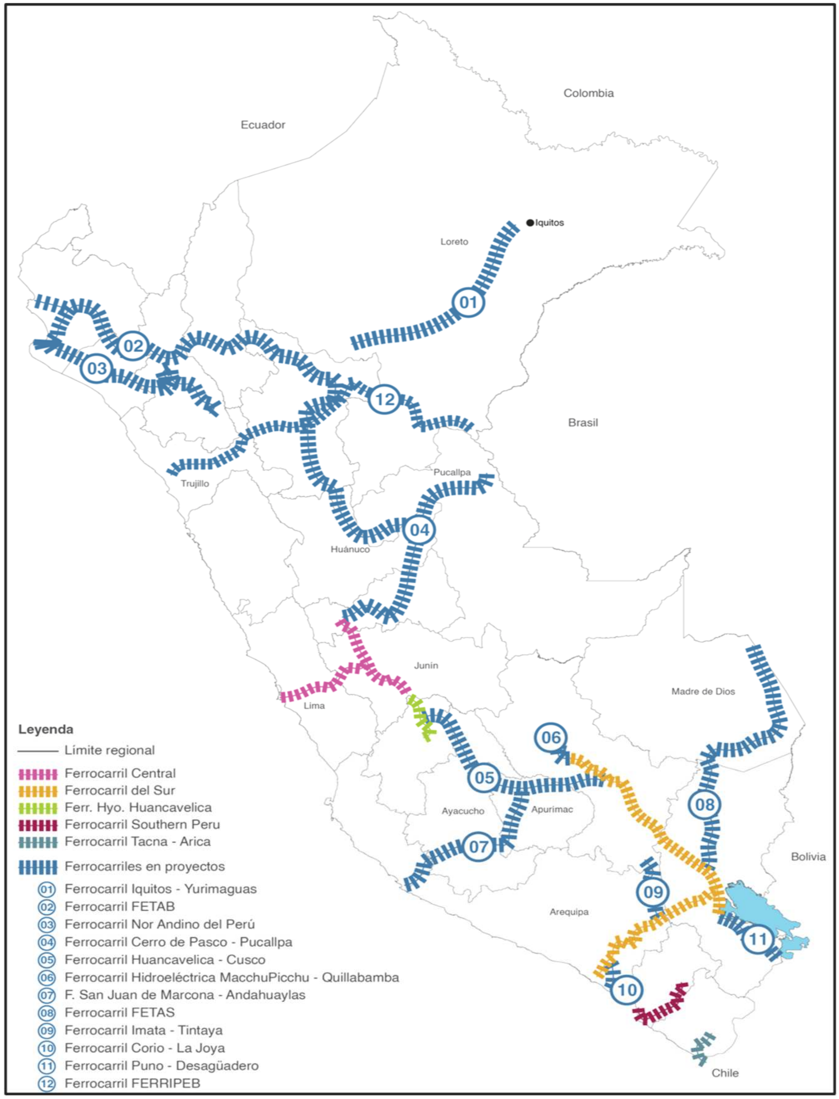
The expansion of the country’s current railway network includes the Lima–La Oroya–Cerro de Pasco railway corridors, the Huancayo Huancavelica Train, the Southern Railway Train and the Tacna–Arica International Train. Additionally, a definitive feasibility study focuses on the investment level of the Interoceanic Corridor: Iquitos–Yurimaguas has been considered and which forms part of the Loreto Regional Government in addition to the Lima Metro and the commuter trains to the south and north of the country’s capital as national project as well, as seen in
Figure 3.
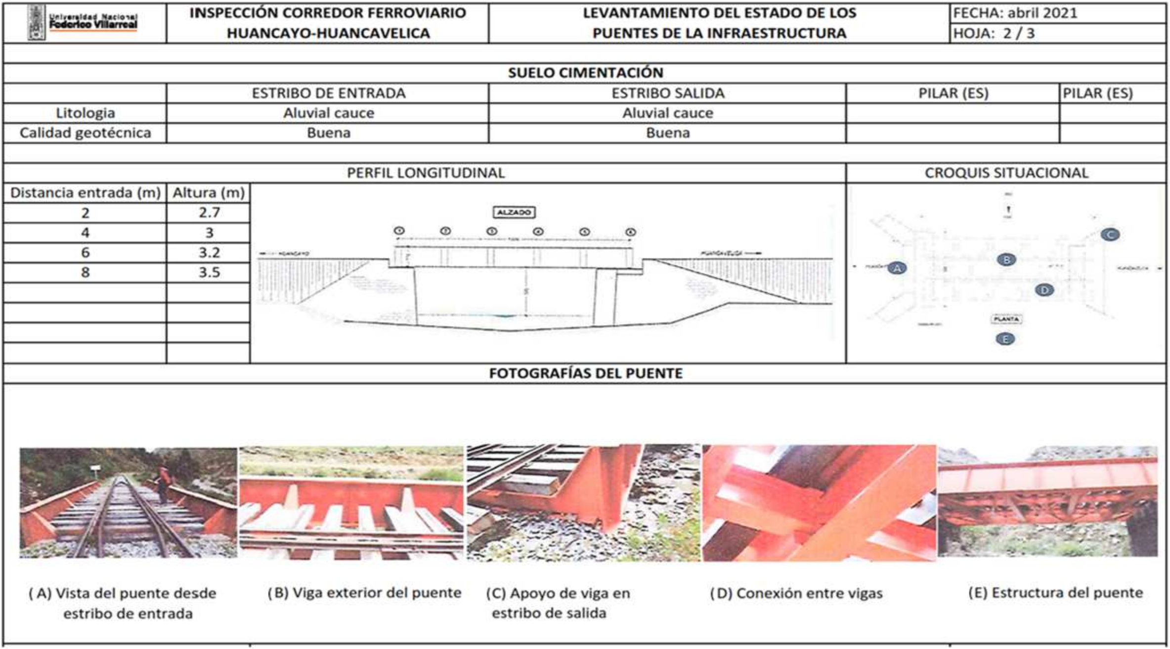
In this regard, we consider it quite important to obtain, before the structural verification of the most important structures, relevant data regarding the geometric characteristics, mechanical characteristics of the structural materials and situational status through on-site visits and the subsequent collection of relevant information, complemented by a survey of their current state as well as an inspection of the details of the reinforcements made according to the modifications in some of them over the last few years of the main railway structure of Perú [
3].
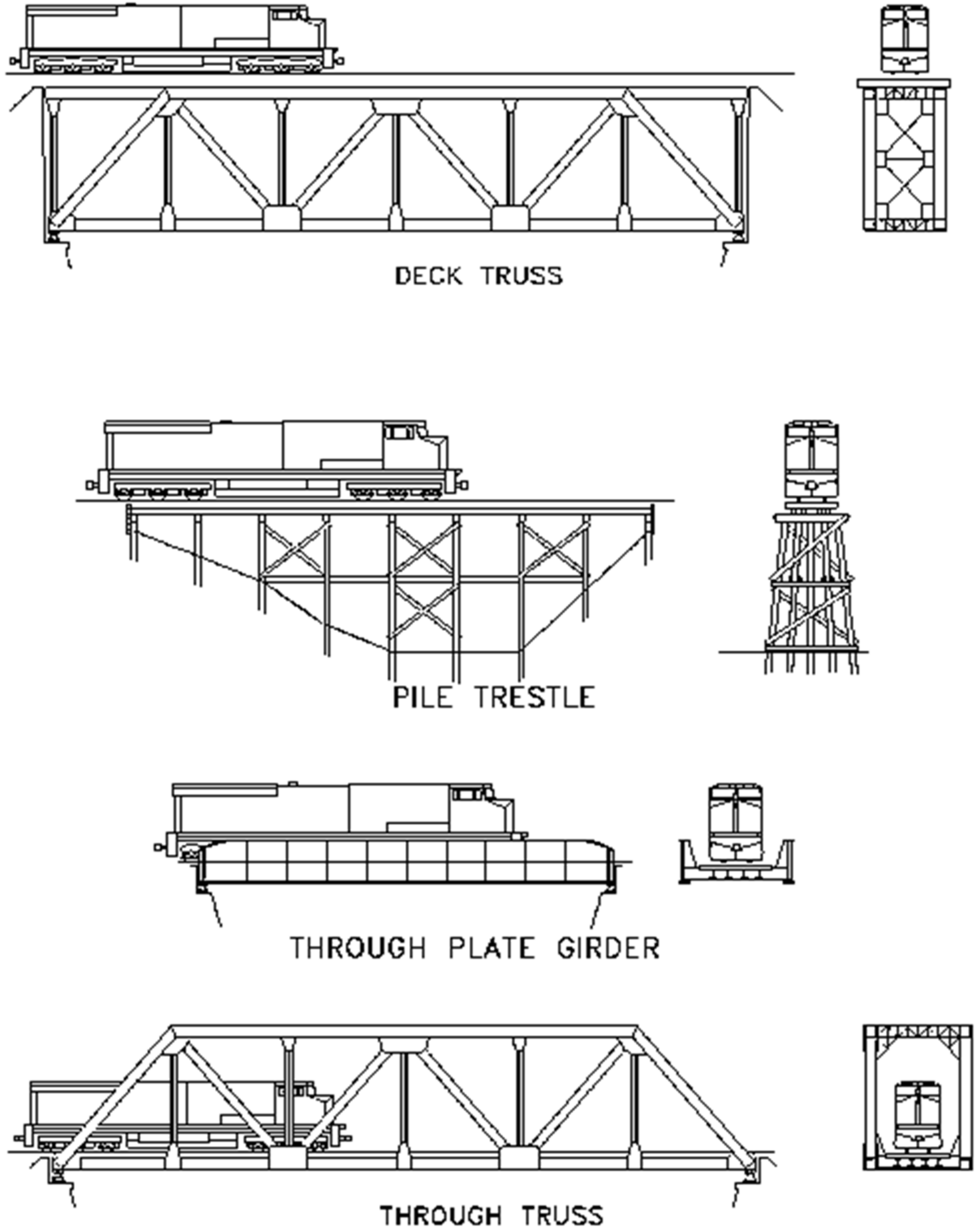
During the inspection of the steel railway bridges, in order to determine their bearing capacity before the static and dynamic analysis, it is possible to identify that most of the typical cross sections along the different railway corridors in Peru correspond to the following types of sections: TPG (through plate girder), DPG (deck plate girder), TTG (through truss girder) and DTG (deck truss girder) [
4]. See
Figure 4.
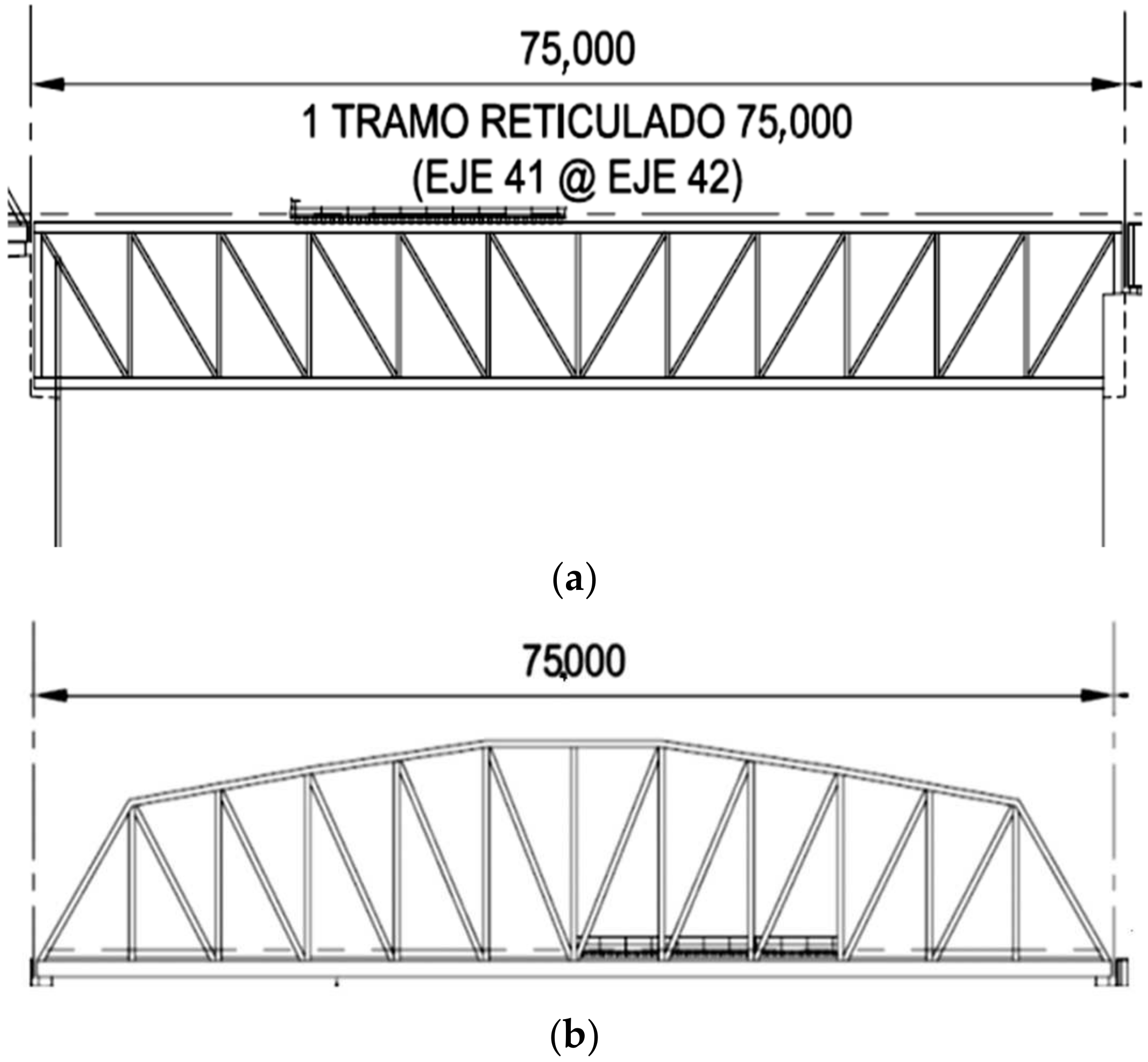
Continuing with the cross sections, the cross sections of the TPG, DPG, TTG and DTG types considered in the feasibility study of the Iquitos–Yurimaguas Interoceanic train that was evaluated by the GORE Loreto have also been considered [
5]; such sections are indicated below: see
Figure 5a,b.
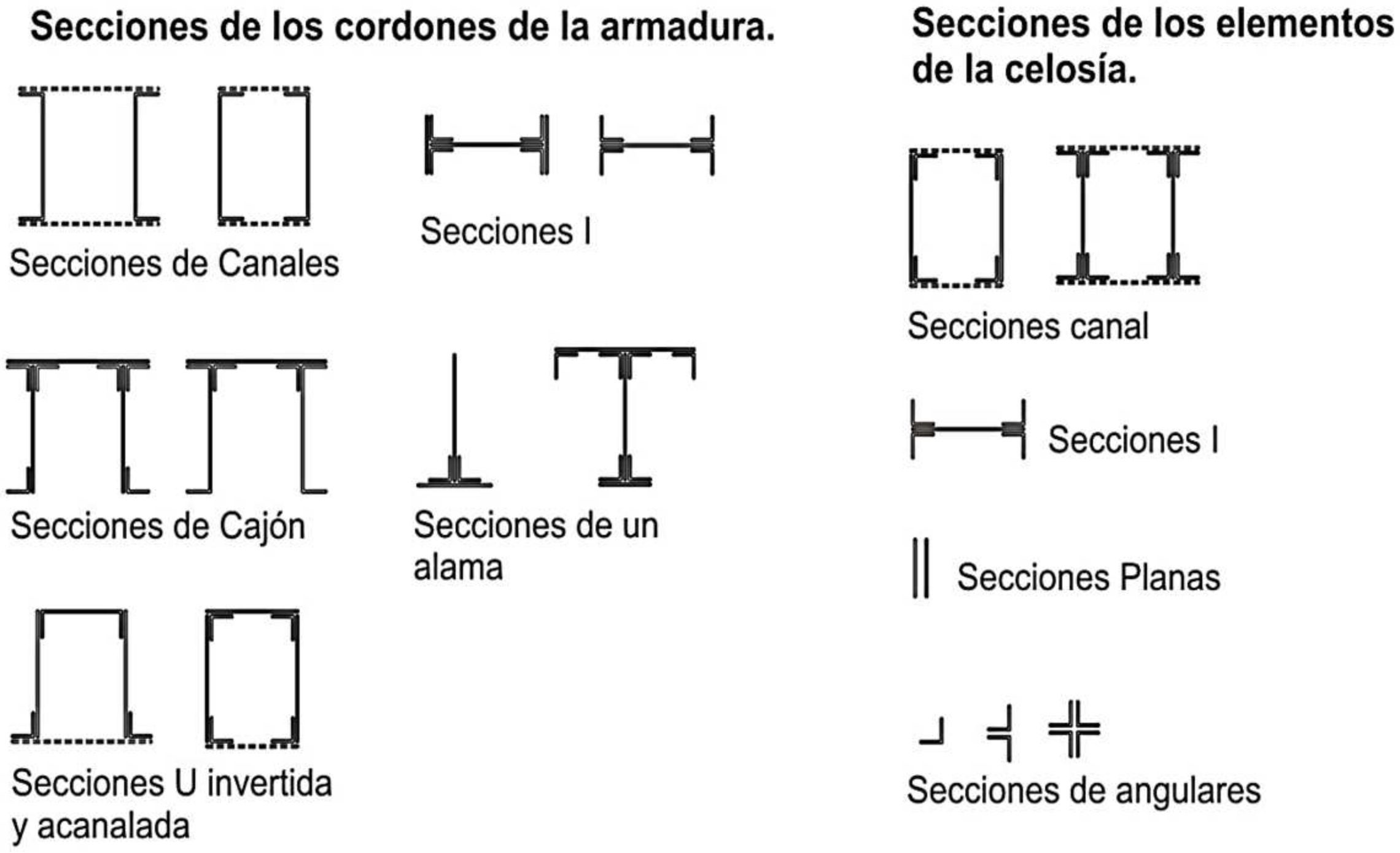
The two types of truss sections are illustrated in
Figure 6a,b, as follows:
The design criteria according to AREMA (American Railway Engineering and Maintenance-of-Way Association), Chapter 15 [
2], prescribes dimensioning based on an Allowable Limits Calculation (allowable stress design) for the elements of a steel structure, while for the elements of reinforced or prestressed concrete, the allowable stress calculation method or the Limit States Calculation method (Load and Strength Design—LRFD) could be used. Consequently, for railway structures, it has been proposed that the elements of steel structures should mainly be designed according to an allowable stress calculation, as prescribed by the AREMA standard, and mainly considering the type of cross section and the structures in these corridors, and that some concrete elements should be designed based on the Limit States Calculation method. This last method will allow the concrete works to have a better uniformity with the American AREMA standard [
6,
7]. See
Figure 7.
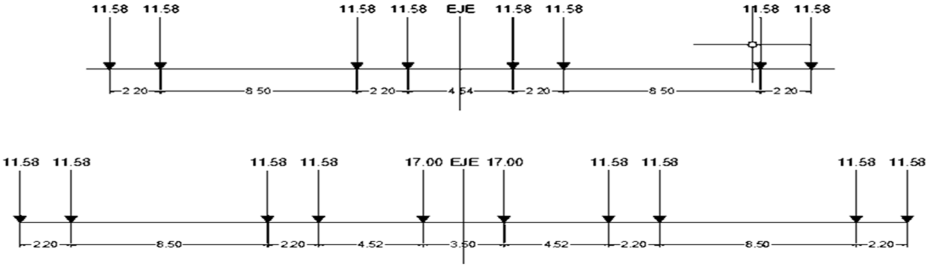
The American standard E-Cooper loads used for this analysis are E-40, E60, and E80, considering the distances and axle loads. See
Figure 8.
As we can see, the challenges they present are their higher initial conditions, as well as their inspection and maintenance criteria, which are more complex due to the large number of details. See
Table 1.
The reference to Chapters 8, 9, and 15 of AREMA [
2] indicates the use of specific guidelines for the design of fundamental railway bridges to ensure compatibility with operational and safety standards in railway infrastructure. The holistic design approach, which includes standards for deflection, fatigue, and materials, shows an integral design philosophy aimed at balancing the strength, durability, and functionality of the structure [
7].
Regarding safety factors, safety margins are incorporated in the design criteria to address uncertainties in loads, material properties, and environmental effects. See
Table 2 and
Table 3.
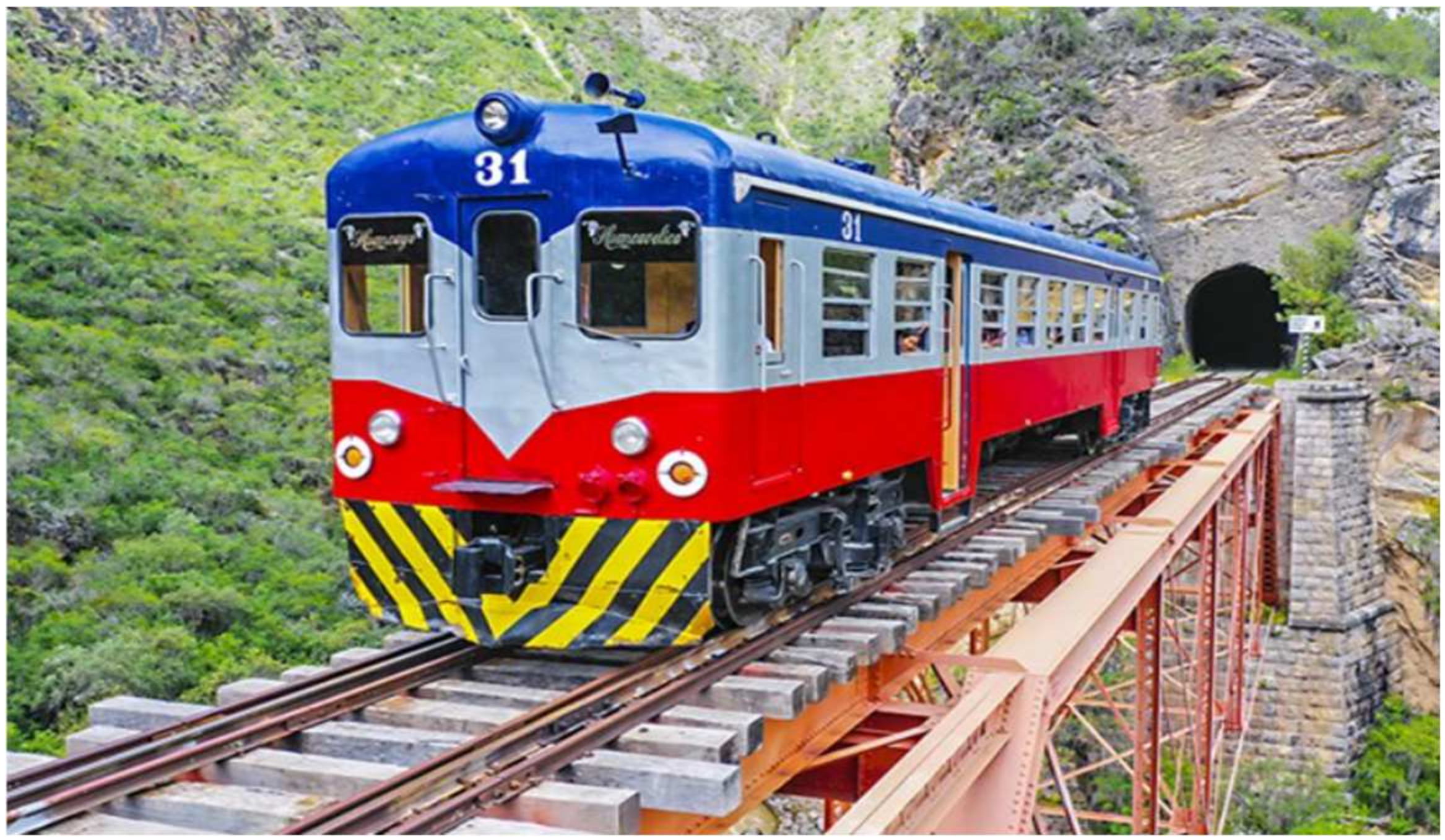
The locomotives used, as well as the year of manufacture, and, in some cases, the year of a major overhaul, are incorporated into the study to assess their impact. These locomotives are designed to operate in the Andes Mountain range of the “Ferrocarril Central Andino—FCCA”, facing extreme gradients and high altitudes (up to 4800 m above sea level). Their robust design and ability to be refurbished ensure their optimal performance on one of the most difficult railway routes in the world [
8].
Also considered are the locomotives and wagons used for the AREMA, especially the 268 K and 286 K wagons, as well as the C39-8 and GT42 locomotive loads from copper concentrate container wagon loads on the FCCA and Peru Southern Railways [
9]. See
Figure 9.
The purpose of the load classifications and considerations in this investigation are to evaluate the structural live load capacity at a critical location of these bridges based on the E-Cooper load parameters, which are based on the AREMA (2023), chapter 17 [
2] standards following the allowable stress method (ASD) through three types of design loads: E-40, E60 and E-80, namely, from the E-Cooper load train, generating a load classification equivalent to the E-Cooper as well as to the 268 k and 286 k cars, the GT42 locomotive load or specific equipment, according to Chapter 15, Section 7.3.2.2 of AREMA [
2] for load classification analysis. See
Figure 10.
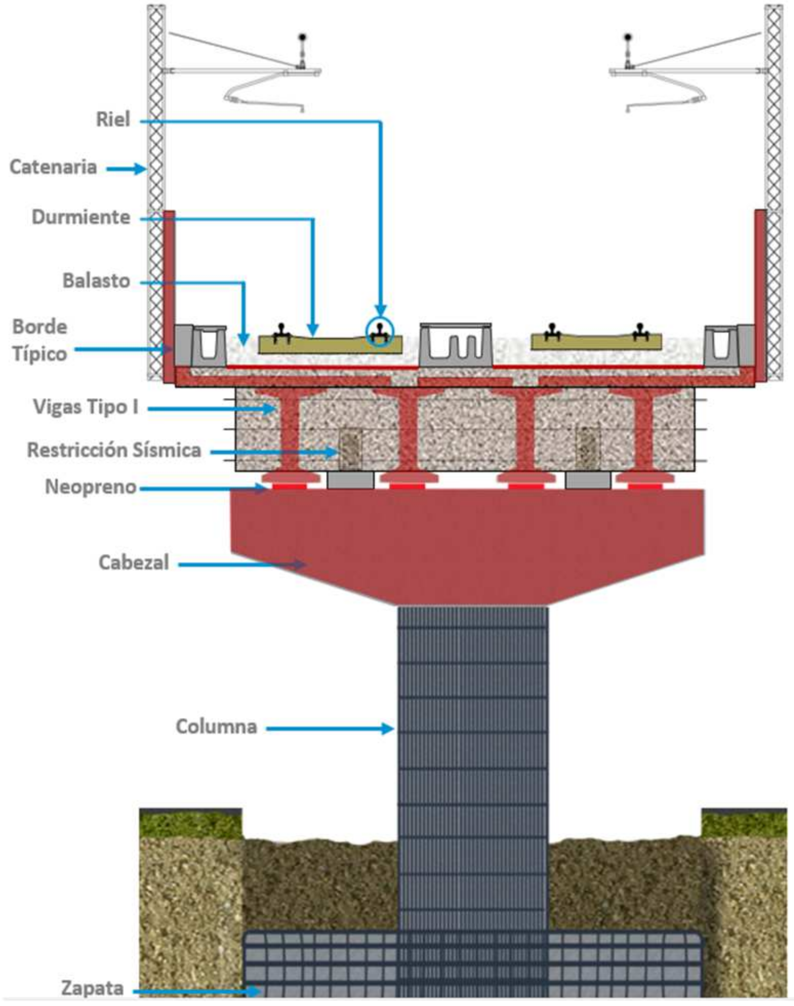
For the Lima Metro, in addition to the Cooper E-80 loads, two types of live train loads (Load A and B) are used [
10,
11], which are the same as the ones used for lines 1 and 2 of the Lima Metro. Additionally, this diagram represents a cross-sectional view of an elevated railway viaduct, showing the superstructure and substructure elements of the bridge, designed to carry railway loads, including those from electrified rail systems (catenary). The rail system supports the trains and transfers loads through the sleepers and ballast into the I-girders that transmit these loads to the pier cap, and subsequently to the column and foundation. See
Figure 11 and
Figure 12.
The following is a reference to the categories of the railway track, which are based on design and maintenance standards according to the Federal Railway Administration FRA [
12]. It is observed that the higher classes allow higher speeds in terms of the maximum speed limits for freight and passenger trains in Kph and Mph. It should be noted that, in the case of passenger trains, these generally have higher limits due to their lighter design and lower impact on the track. See
Table 4.
Eventually, considering trains that increase in speed, one option could be to upgrade to E-60 or E-80 freight trains, which are more suitable due to their greater capacity to handle the dynamic forces generated by trains [
13,
14]. In addition, the traffic projection has been evaluated, between 2.5 M tones and 3.0 M tones as the maximum; if heavy train traffic is expected to increase, E-60 and E-80 loads offer a greater margin for future load increases without compromising the safety or functionality of the bridge after evaluating and renewing the locomotives. See
Figure 13.
Finally, for normal and maximum rating, AREMA Chapter 15, Section 7.3 [
2] provides guidance for deriving normal and maximum ratings, where the normal rating is the appropriate capacity for the day-to-day use of a structure and the maximum rating is the appropriate capacity for occasional use. For both ratings, several factors like specified speed for impact and allowable stresses and exerted loads are considered. For the normal rating, allowable stresses are based on AREMA Chapter 15, Part 1-Design, Table 15-1-11, [
2], whereas, for the maximum rating, allowable stresses are allowed to be increased as per AREMA Chapter 15, Table 15-7-1 [
2]. Finally, the values for allowable stress are showed for flexure and shear under the normal rating. See
Table 5.
3. Results
Below are some of the significant aspects involved in the structural analysis of railway bridges, with the results of various railway projects carried out and for this article the process of analysis and the verification of the structural capacity of railway bridges and to warn about certain aspects that may influence the verification of the structural capacity of railway bridges as well as routine maintenance programs.
The results for various types of bridges with different spans and a slenderness ratio of L/640, obtained using different criteria for maximum tensile and compressive stress under dead loads, live loads, wind loads, temperature loads, lateral forces, braking loads and longitudinal forces for E80, E60 and E40, as well as AREMA’s railcars in the characteristic combination at the most stressed section, indicate a good-to-medium load-bearing capacity for some of these bridges. This suggests the need for a periodic strategic plan for these railway bridges.
Also, the thermal stresses are presented according to the different temperature gradients that summarize the typical ranges for the coastal zone, the mountainous region and the Rainforest region in Peru. These values consider the annual variations, the extremes and the average differences that impact the design of bridges. See
Table 8.
This table summarizes the temperature-related factors in different regions of Peru and their impact on bridge design. See
Table 9.
The natural frequency of the bridges ranges between 2.08 and 3.06 Hz, with which they can interact with the frequencies of the dynamic loads of trains reaching a speed of up to 60 km/h, and so resonance with a main excitation frequency is unlikely, but the dynamic effects due to transient vibrations must still necessarily be evaluated by a much more detailed dynamic analysis, which could be conducted in another article.
Also, a summary of the frequencies for a typical case of a 35–55 m bridge for charges E-Cooper is shown below, where the values of mass, stiffness and the natural frequency of a TPG, DPG and truss bridge are well below the values obtained with the typical excitation frequencies of trains. So, a higher frequency will reduce the probability of resonance with the structure. See
Table 10.
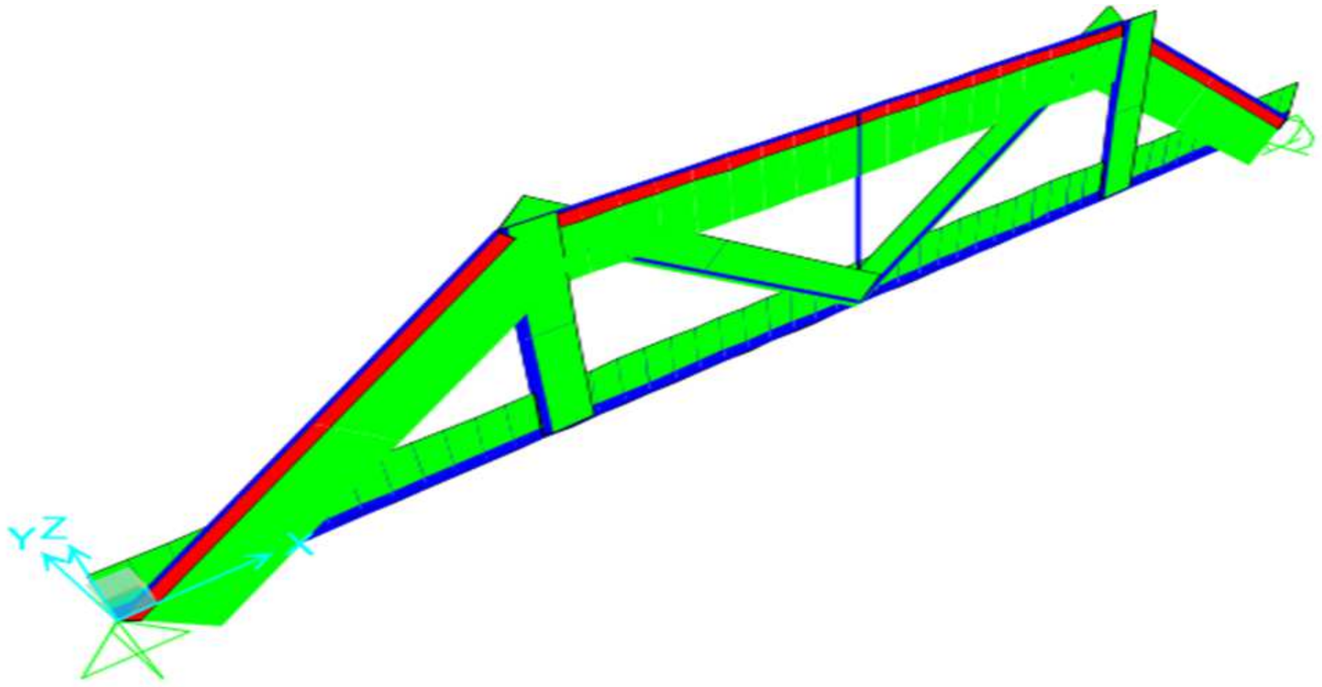
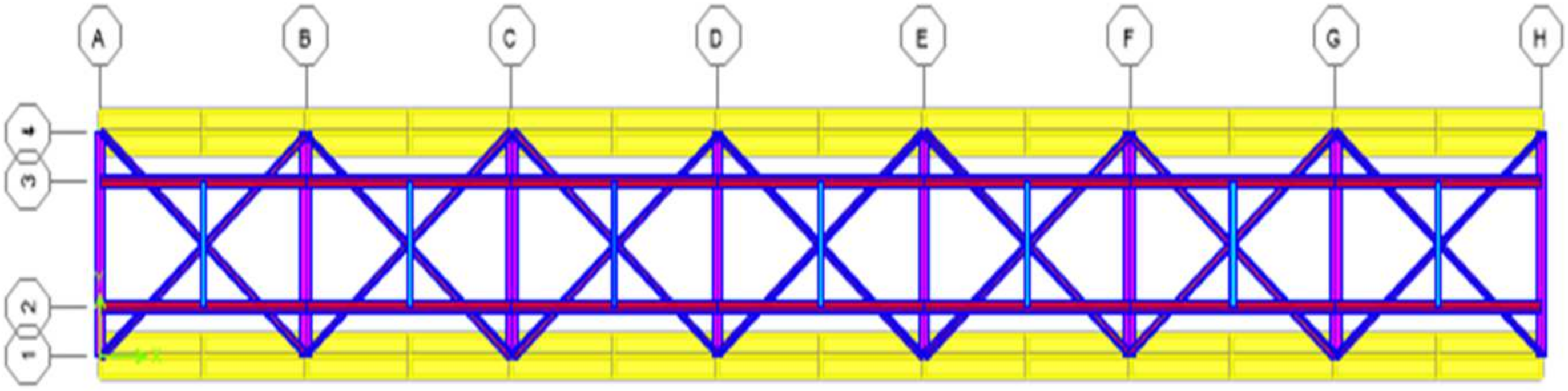
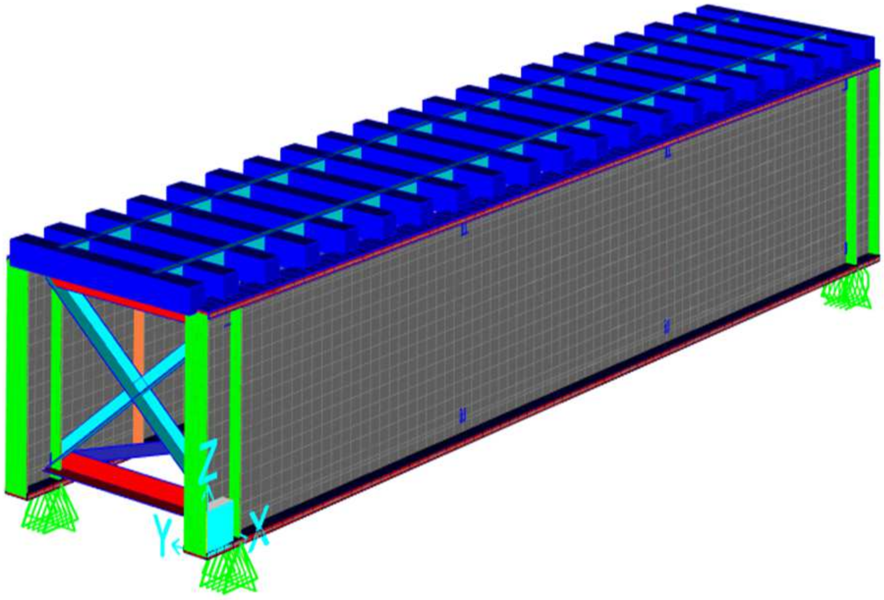
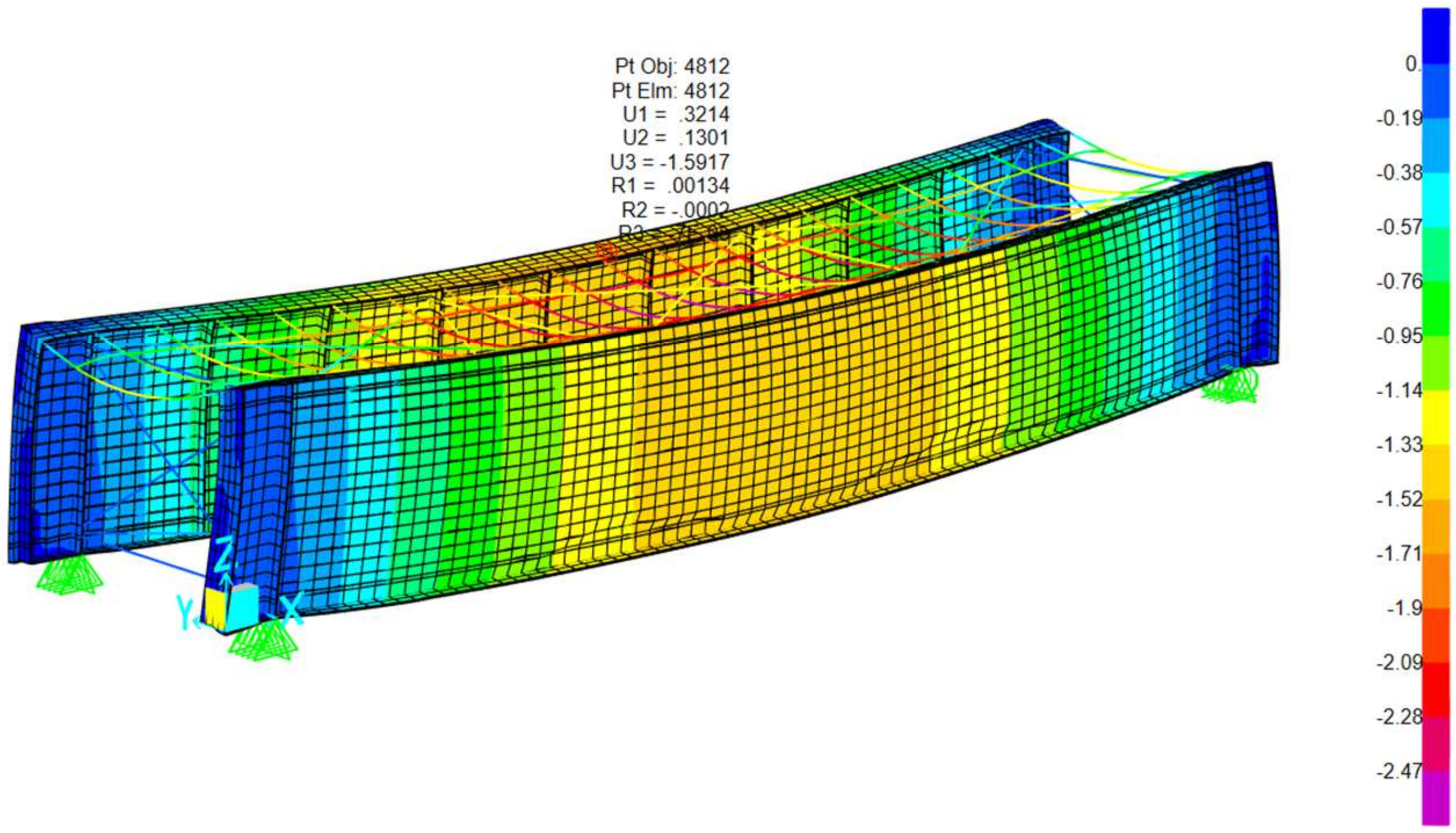
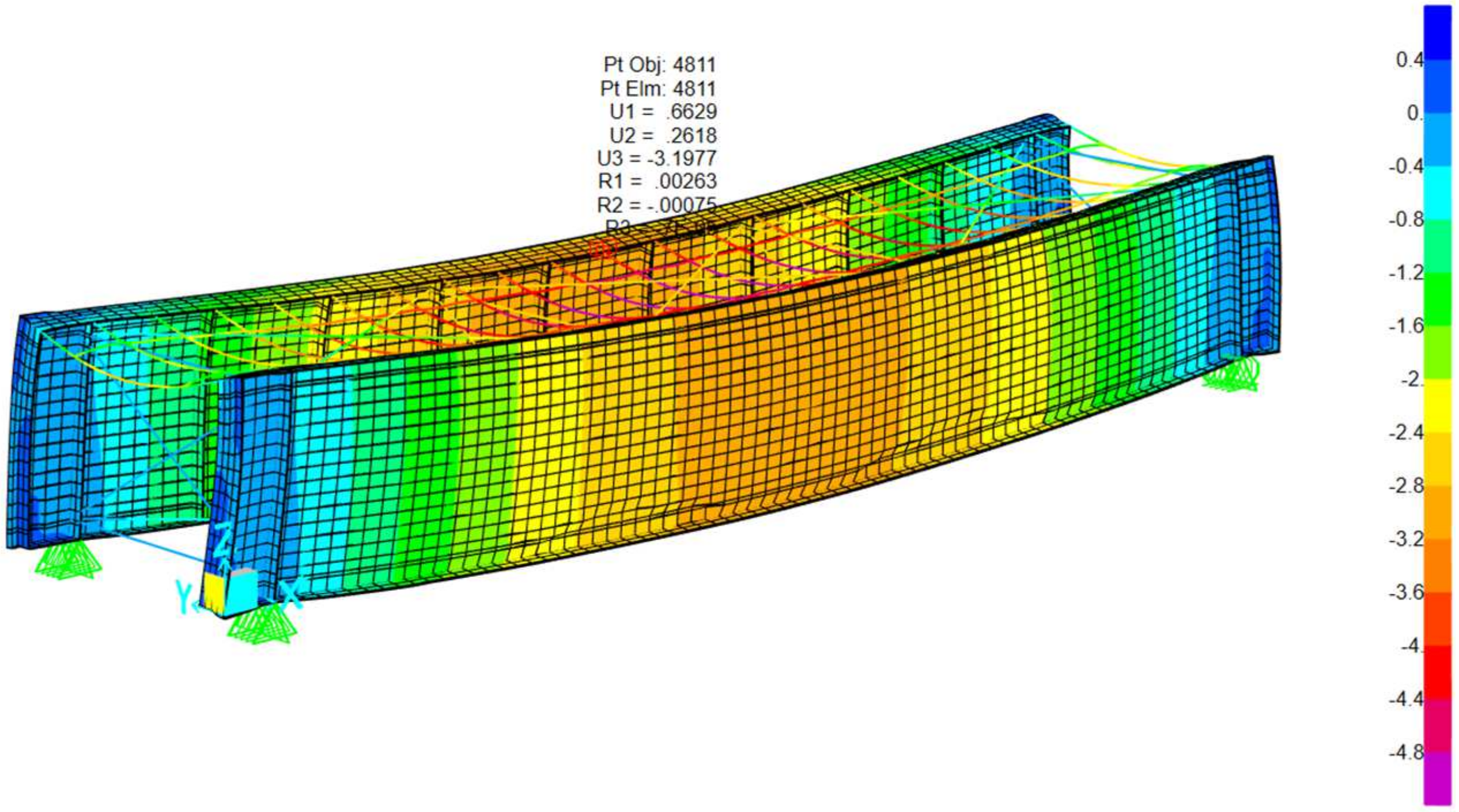
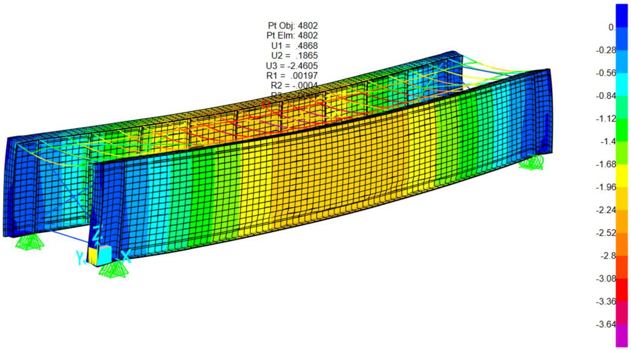
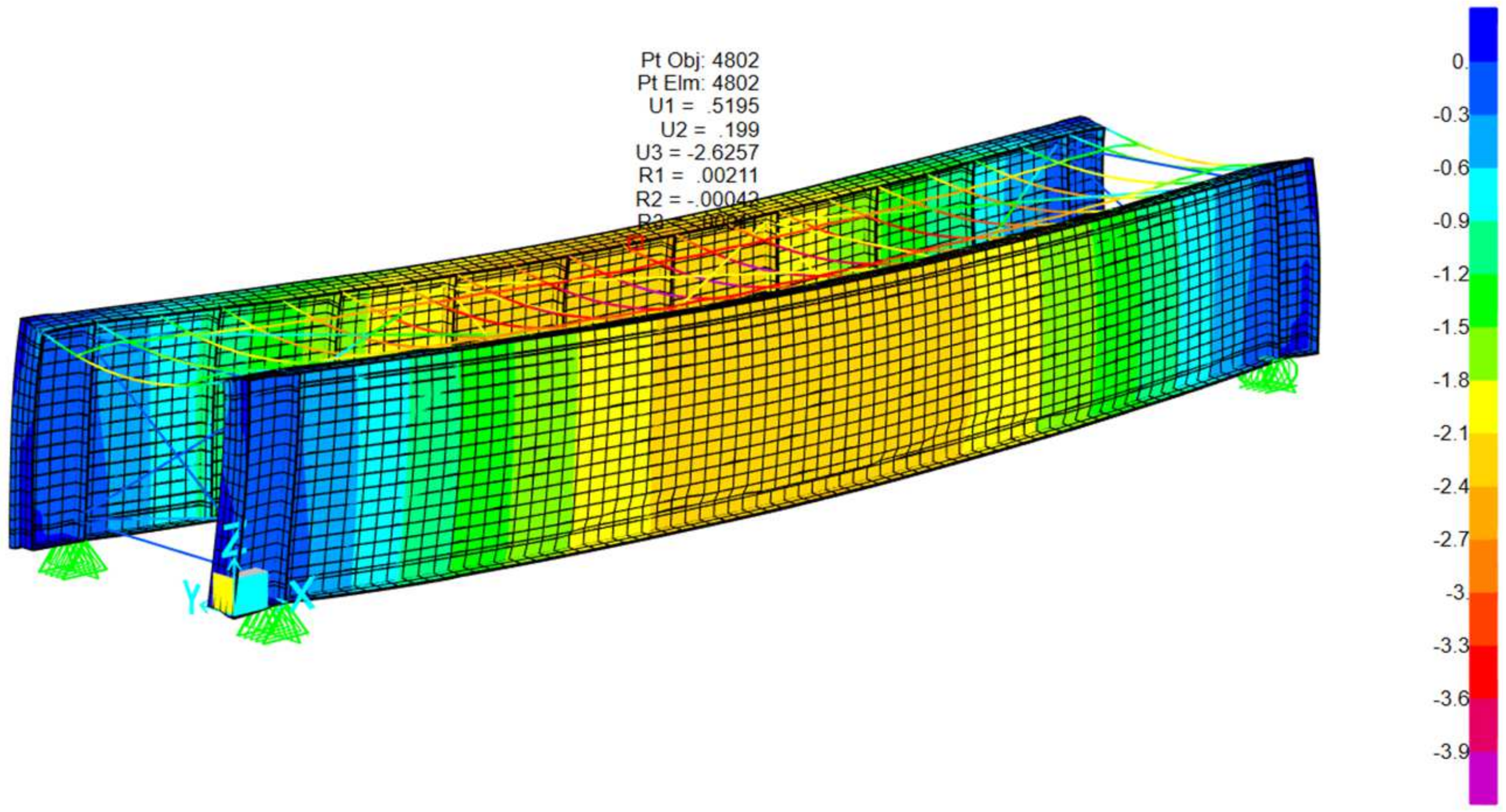
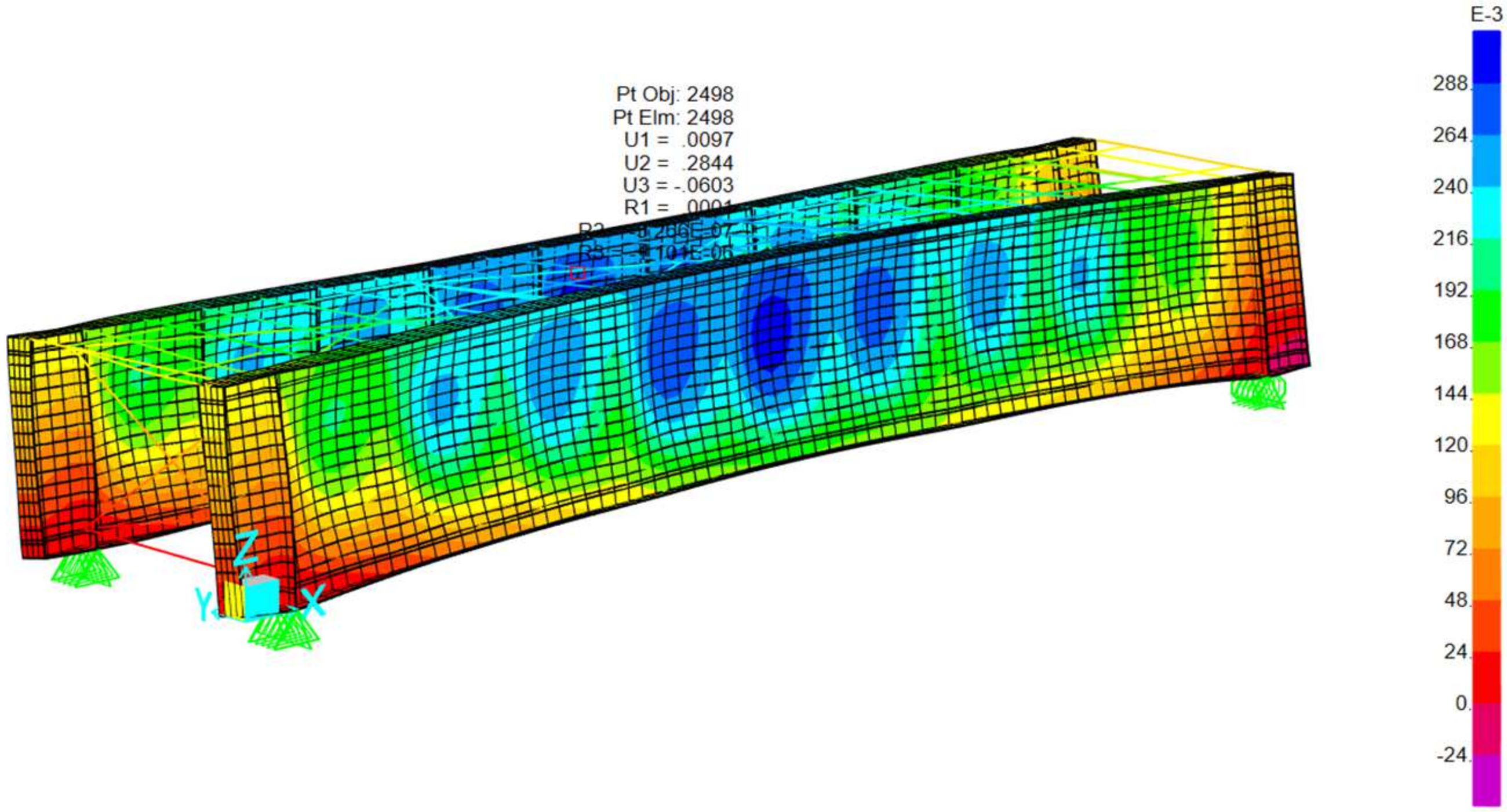
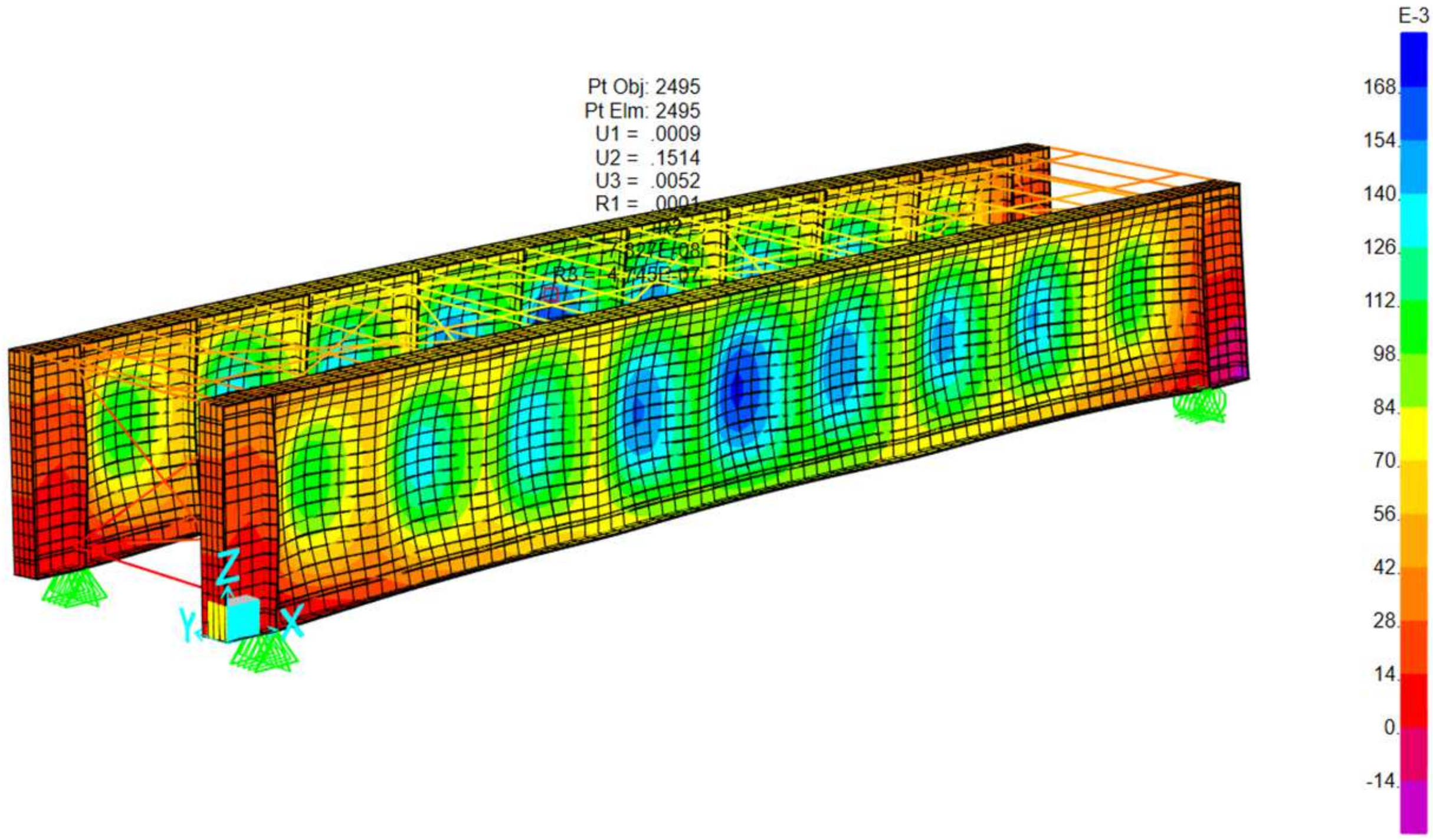
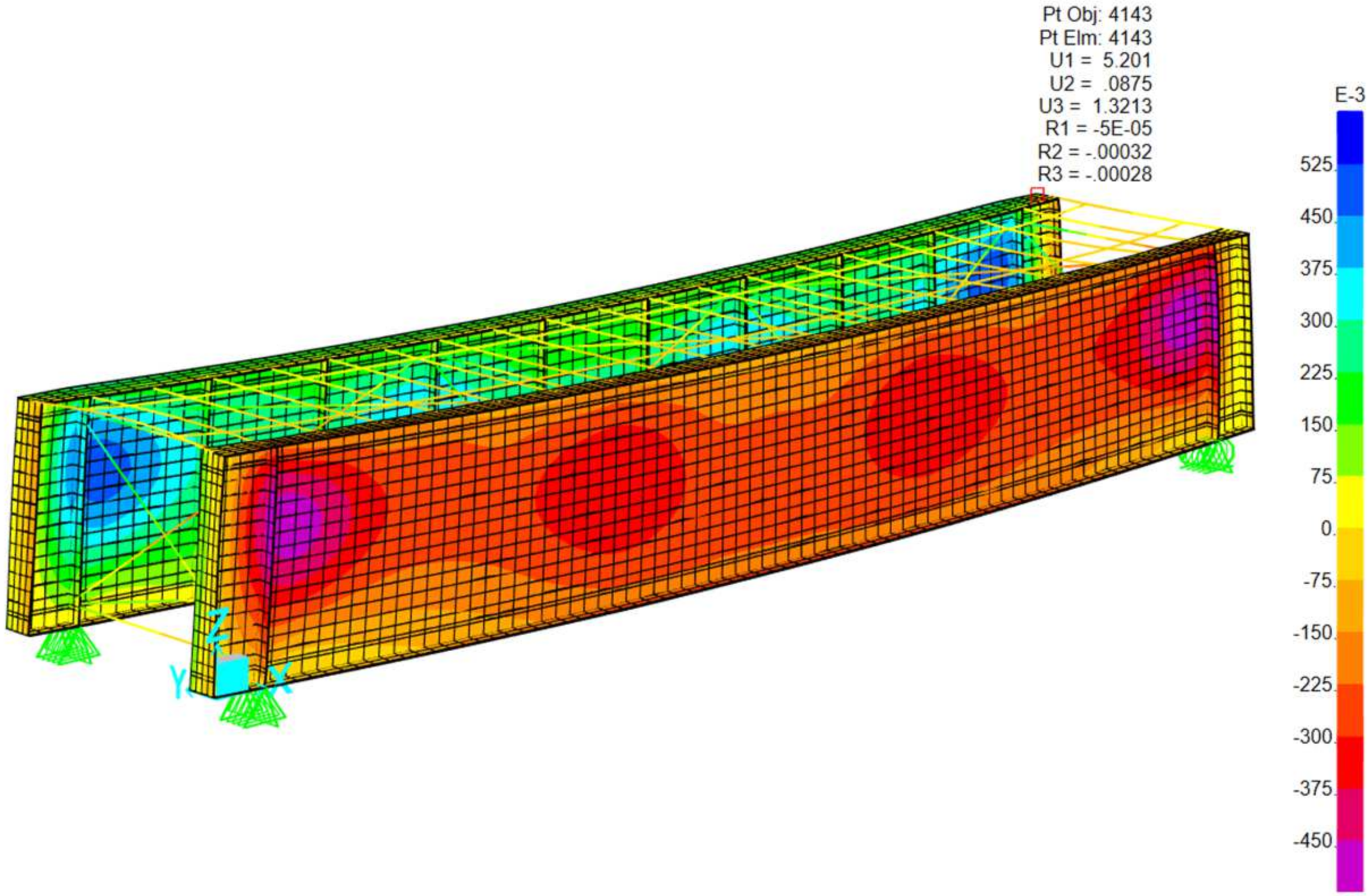
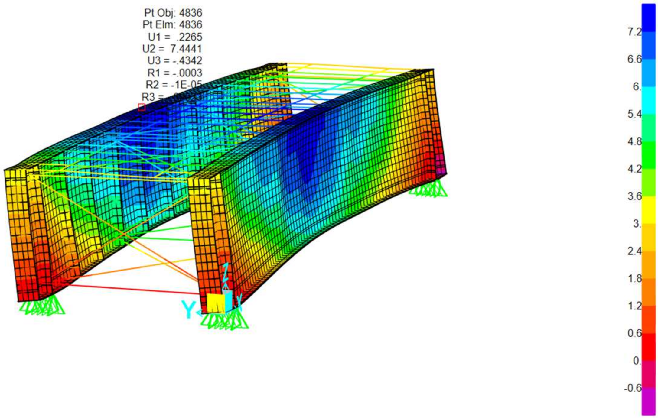
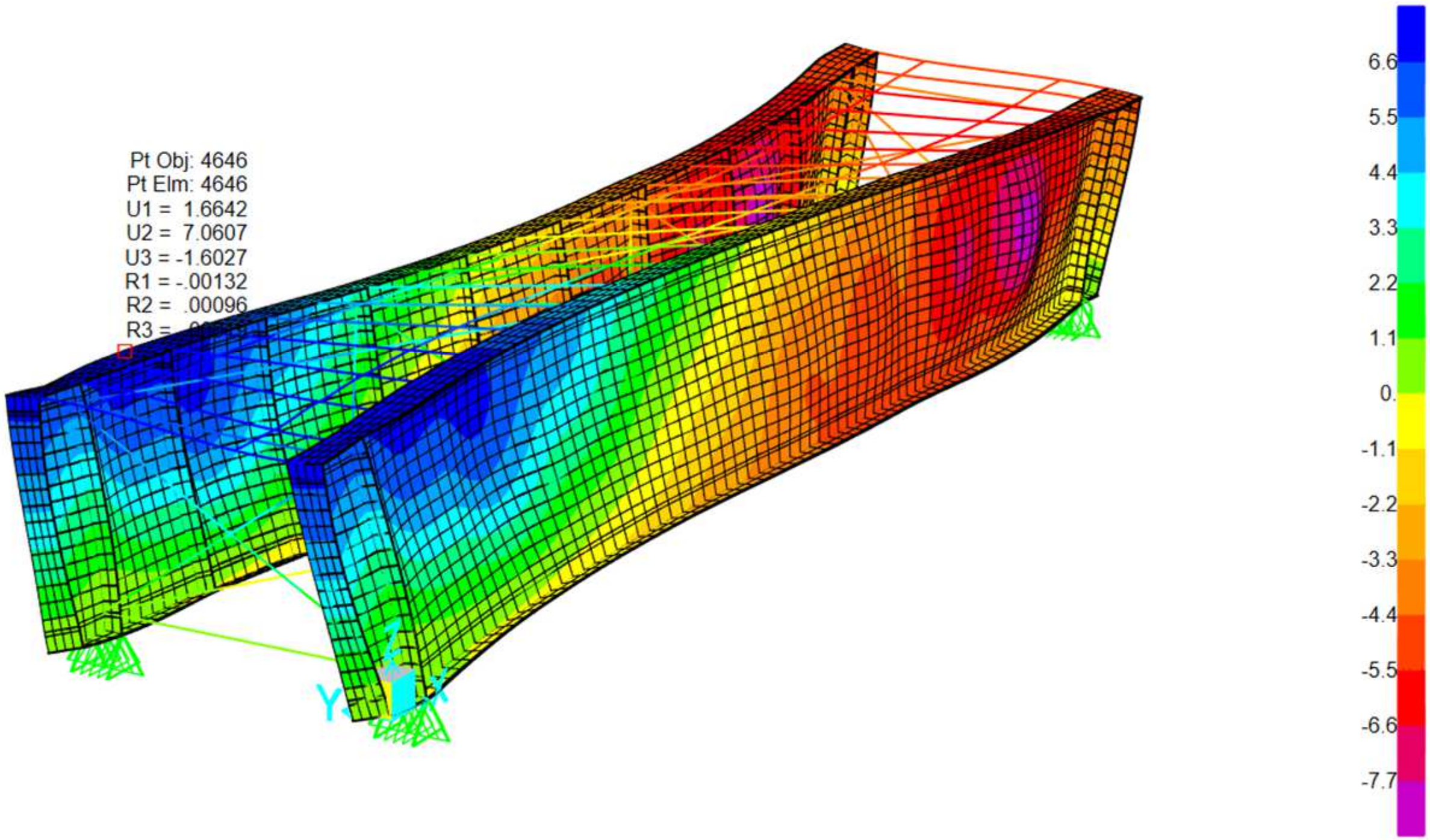
The image presents a 3D finite element model of a rectangular steel-framed structure representative of a railway bridge deck with a through plate girder system. Below is a breakdown of the key structural components: Vertical elements: main structural steel girders. Top horizontal members: timber beams. Diagonal braces: represent lateral bracing systems designed to resist shear forces and lateral loads such as wind and seismic effects. Mesh surfaces represent diaphragms contributing to overall stiffness. Regarding boundary conditions, the support symbols at the base indicate pinned supports, simulating the restrained conditions typically found at girder bearings. The following sections illustrate the various loading conditions applied to this type of railway bridge cross section, including: self-weight and permanent load, load live, E40, 60,80 Cooper—live load, 286 K live load (Hopper), loaded and unloaded transverse wind, load Temperature load and seismic loads. Refer to
Figure 27,
Figure 28,
Figure 29,
Figure 30,
Figure 31,
Figure 32,
Figure 33,
Figure 34,
Figure 35,
Figure 36,
Figure 37,
Figure 38 and
Figure 39 for detailed visualization of these loading conditions:
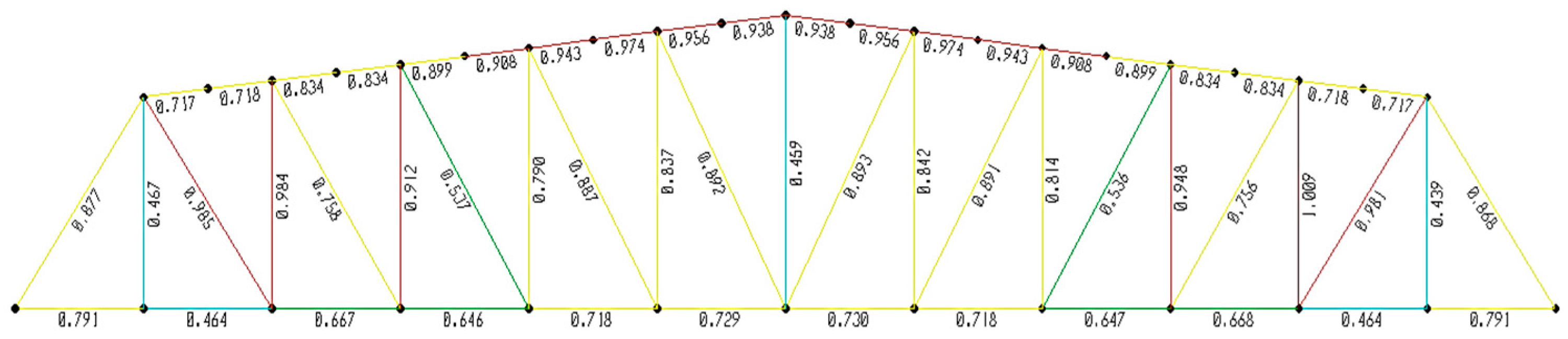
The truss bridge has the highest natural frequency (3.06 Hz), which makes it less prone to resonance with the typical frequencies of the forces generated by trains. This structure is highly efficient in load distribution, which results in greater rigidity compared to the TPG and DPG configurations, as seen in
Figure 27,
Figure 28,
Figure 29,
Figure 30,
Figure 31,
Figure 32,
Figure 33,
Figure 34,
Figure 35,
Figure 36,
Figure 37,
Figure 38 and
Figure 39.
The allowable stresses used in normal ratings are determined as per AREMA Chapter 15, Section 7.3.1.1 [
2]. Allowable stresses are calculated using the procedure described in
Section 1. Introduction, which is based on AREMA Chapter 15, Table 15-1-11 [
2]. The allowable stresses calculated for a normal rating are summarized as follows in
Table 11:
The allowable stresses used in the maximum rating are as per AREMA Chapter 15, Section 7.3.1.2. AREMA Chapter 15, Section 7.3.3.3 and Table 15-7-1 [
2] provide the allowable stresses for the maximum rating. The allowable stresses calculated for the maximum rating are summarized as follows: see
Table 12.
In order to assess the structural stresses, to determine whether the different elements of the bridge (beams, transverse, longitudinal) can withstand each type of equipment load and to identify the most affected elements according to the types of loads, inspections, maintenance and rehabilitation can be prioritized: see
Table 13.
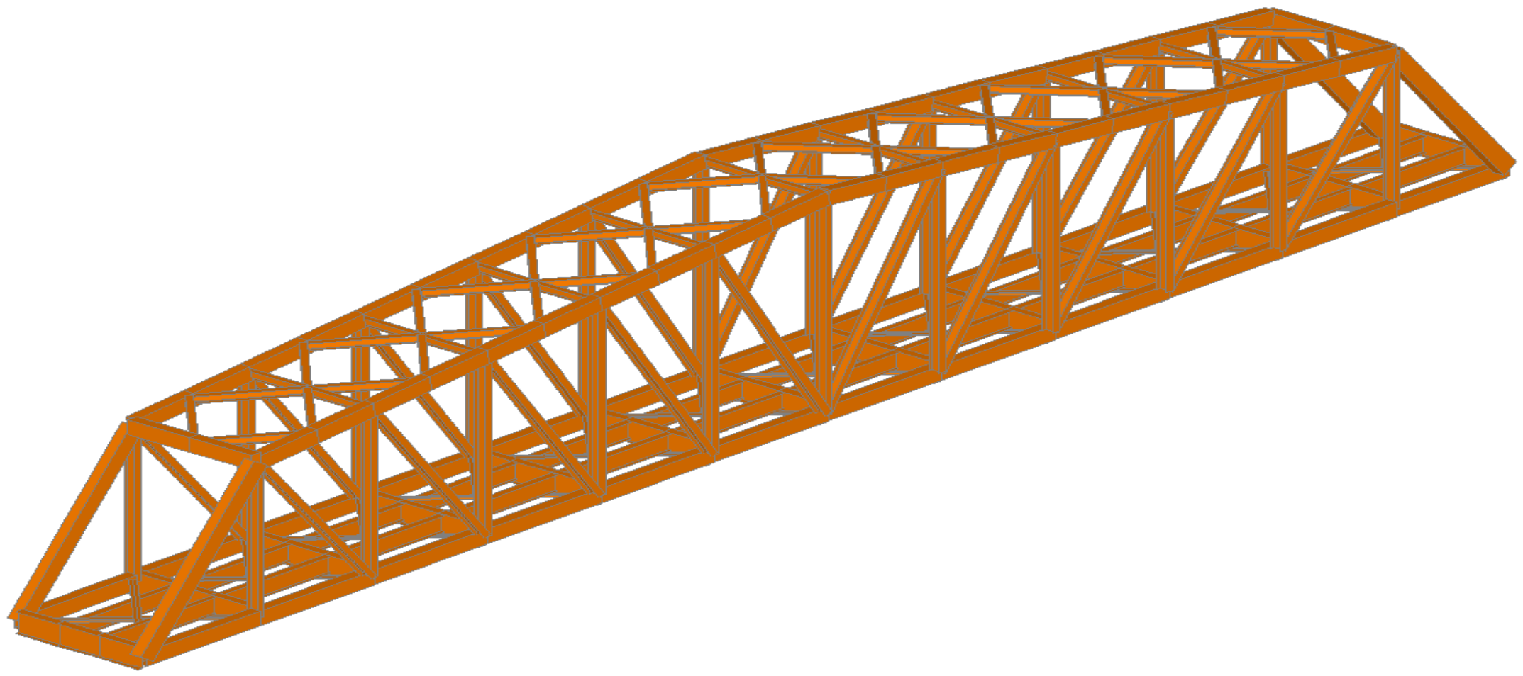
The three-dimensional modeling of the structure “Infiernillo Bridge” has been carried out considering the truss section with an upper deck and another section of the DPG beam. This structure has been subjected to the E-Cooper E-40, E-60 and E-80 loads in addition to the locomotives and wagons used for the FCCA and Southern Railway, such as the C38-9 and GT42 locomotives, and the 268 K and 286 k wagon loads. See
Figure 40.
The detailed results for the rating of bridge members and equipment is presented for DPG bridges that have the capacity to support the 268 K, 286 K, GT42 and C38-9 railcars and locomotives at 60 kph under normal and maximum rating criteria from AREMA. Fatigue stress is not a concern, as the amount of traffic is less than the AREMA determine threshold for these lines railroad in Peru. The minimum normal rating for bending is E 67.7 for the floor beam, while the maximum equipment load for bending is E 60.3 for the 286-k car. The above rating analyses are based on inspections and calculations. See
Table 14.
4. Discussion
The steel structures comprised variable sections of longitudinal and transverse girders and main plate girders with important depths and truss elements. Transverse girders connected to longitudinal beams with sections varying between 450 cm in width and 0.9 to 1.2 m in depth. The longitudinal beams were supported at each span by rectilinear elements placed on steel piers, which could rise up to 15 m in height.
Special attention was given to the dynamic behavior of these bridges, particularly due to their large spans and the challenging rheological conditions in Peru. Spatial analysis models were used to simulate train passages at speeds up to 60 km/h, and the maximum acceleration under moving loads was calculated to be 1.958 m/s
2, well below Peruvian standards recommendations in
RNE-E.030 [
21] limit of 0.3 g. This outcome supports the notion that optimized construction methods and materials can lead to significant cost savings without compromising the safety or performance of these bridges.
Regarding the bending capacity, the minimum normal rating for the floor beam was found to be E 67.7, indicating that the beam can safely handle typical loads without exceeding the design limits. In contrast, the maximum equipment loads for bending, which corresponded to the 286 K railcar, resulted in a rating of E 60.3, indicating that while the bridge can support these heavier loads, there is a smaller margin when compared to normal loading scenarios. This highlights the importance of closely monitoring the bridge’s load conditions and considering periodic maintenance or reinforcements if future traffic levels or loads increase.
The evaluation of the DPG bridges revealed that they were structurally capable of supporting the designated railcars, including the 268 K, 286 K, GT42 and C38-9, operating at 60 km/h. This capacity was ensured under both normal and maximum rating criteria, making the bridges sufficiently robust for the current operational conditions. The analysis demonstrates that the current traffic volume is significantly below the AREMA threshold, which is why fatigue does not pose an immediate concern for the bridge structures.
The evaluation of various bridge types revealed that through plate girders (TPGs) required larger girders to manage the concentrated E-Cooper load, resulting in significant bending and shear forces. Their dynamic amplification factor (DAF) was high due to limited lateral stiffness, and fatigue was a concern at the welded connections. These bridges were more prone to fatigue failure unless extensively reinforced, and their ability to handle cyclic loads and vibrations was limited. In contrast, deck plate girders (DPGs) provided better load distribution, reduced dynamic amplification and improved lateral stiffness, lowering the likelihood of fatigue. They required less reinforcement than TPGs, and although the material costs were higher due to the larger deck area, they offered easier maintenance. Truss bridges (TTGs and DTGs) efficiently distributed axial forces, resisted dynamic amplification and had excellent fatigue performance due to their high rigidity. They were ideal for heavy traffic and high-speed trains, though their initial cost and maintenance complexity were higher. Overall, while these bridge types each had distinct advantages and challenges, their performance was more influenced by their design and material choices than by their construction era.
This analysis is based on a series of thorough inspections, which ensure that the structural integrity and load-bearing capacity of the bridges are well understood. However, continued monitoring and maintenance are essential to ensure long-term safety and operational efficiency, particularly if traffic patterns or the weight of railcars change over time. This approach allows for proactive decision-making regarding potential upgrades or reinforcements to maintain bridge reliability.
Given that the speed of trains and the potential evolution of traffic were crucial factors in determining the durability and safety of railway bridges, selecting the E-60 Cooper load during the initial phase is a prudent decision. The E-60 load offers a significant safety margin against higher dynamic loads, especially if future projections indicate an increase in heavy or high-speed train traffic. While the E-60 load is sufficient for current traffic conditions, choosing it ensures that bridges are prepared to withstand not only the existing loads but also additional stresses from increased speeds (up to 60 km/h) and traffic volume. This proactive approach can help extend the infrastructure’s service life and reduce the need for early rehabilitation.
5. Conclusions
Railway engineering in the country is important due to the proposals for the expansion of the national rail network, but still presents some important deficiencies such as a lack of regulation, standards and professional specialization in the railway industry. Therefore, this research seeks to establish a knowledge base and a technical guide for analysis procedures and for verification of the bearing capacity of existing railway structures and their suitability for subsequent technical studies.
Analyzing these types of problems allows us, for example, to consider four (4) railway structural cross section typologies (DPG, TPG, DTG and TTG) that present a certain level of complexity in optimizing materials and present complex solutions in the different railway corridors in the Peru. As a counterpart to this, achieving results with greater precision is becoming increasingly necessary, and these results have been obtained using the finite element method (FEM) criteria through SAP2000 software, edition 2024 by incorporating the deficiencies identified in the visual inspection reports.
The strategy must emphasize the integration of cutting-edge tools such as finite element modeling (FEM) and advanced materials for rehabilitation. Continuous professional development for maintenance personnel ensures the application of the latest diagnostic tools and practices. Significant results were obtained which allowed for the verification of the load-bearing capacity of these structures in compliance with the E-cooper loads from the AREMA standard 2023 [
2], such as E-Cooper E-40, E-60 and E-80 loads. This includes considerations for 268 K and 286 K as well as the copper concentrate container wagon loads on the Central and Southern Railways, such as the GT42 and C39-8 FFCA locomotives.
The railway bridge maintenance strategy for Peru must be focused on ensuring safety and optimal performance by combining preventive, predictive and corrective maintenance. Regular inspections are critical, with comprehensive assessments performed annually and more frequent inspections in high-stress or extreme environments. Advanced technologies, such as real-time monitoring systems, drones and vibration sensors, could be employed to detect early signs of wear, predict potential failures and enable sustainable maintenance. Many of the railway bridges in service are deteriorating due to physical and chemical aging, as well as excessive deformations caused by the increase in live loads, the greater frequency of loads, and problems related to the deterioration of some elements in different structures. However, many of these structures still maintain good structural behavior.
Regarding resistance and deflection, the bridges comply with the criteria of resistance and deflection under the E-60 load. DPG, TPG and truss bridges are suitable for a maximum span of 40 m under E-60 loading and of 75 m for truss bridges, provided that appropriate inspection and maintenance plans are implemented. The maximum operational speed should be limited to 60 km/h, and some structural elements may need replacement. Additionally, reinforcement using cover plates and corrosion protection measures should be considered to extend the lifespan and improve the structural integrity of the bridges.
In summary, if train speed is an important factor and if heavier or faster traffic is anticipated, E-60 loading would be the best option to ensure the long-term durability and safety of these bridges. For the greater implementation of this load, a program of reinforcing the superstructure and infrastructure will be necessary in many of these structures.


