Abstract
To address the critical issue of low reliability caused by fault impacts in large-scale wind farms transmitting power over long distances via flexible DC transmission systems, this study proposes a collaborative solution. First, a new protection scheme integrating variable quantity differential protection, steady-state quantity differential protection and zero-sequence differential protection is proposed. By establishing a refined model of a wind farm with a flexible DC system, the adaptability of the differential protection for the outgoing lines is checked. Simulation results show that the sensitivity of metallic faults within the protection zone is better than 3.0, and the protection reliably remains inactive for faults outside the protection zone. Second, an innovative fault ride-through strategy combining self-regulating resistor circuits with wind farm MPPT load reduction is proposed. During faults on the receiving grid, the DC voltage fluctuation is controlled within 1.05 p.u. through graded switching of resistor modules and dynamic power regulation. This solution offers both rapid response and smooth fault ride-through characteristics, significantly improving the feasibility and economic viability of wind farm integration via flexible DC transmission.
1. Introduction
With the global energy structure transitioning toward renewable energy, wind power installed capacity continues to grow rapidly [1,2]. Flexible DC transmission technology, due to its advantages such as independent active/reactive power control and low line losses, has become a key solution for long-distance wind power transmission [3,4,5]. However, integrating wind power via flexible DC systems faces two core challenges [6,7]:
1. Protection challenges caused by weak feed characteristics at the sending end:
As a weak power source, wind farms exhibit significant weak feed characteristics during faults on outgoing lines, including low fault current amplitude, severe phase shifts, and high harmonic content [8,9]. These characteristics degrade the performance of traditional differential protection, reducing sensitivity and even risking failure to operate during high-resistance grounding faults. The limited short-circuit current of flexible DC systems (e.g., converter current limiting and nonlinear fault waveforms) further reduces the sensitivity of traditional differential protection [10,11]. Improving existing differential protection schemes to adapt to the fault characteristics of weak feed systems has become a focus of current research.
2. FRT capability requirements at the receiving end:
When flexible DC lines are connected to the AC grid via converter stations, they must possess strong FRT capability. During short-circuit faults on the receiving AC system, the converter station must maintain grid-connected operation and provide dynamic reactive power support to assist voltage recovery [12]. However, DC voltage fluctuations and power imbalances during faults may trigger converter station blocking, threatening system stability. Traditional unloading circuits or single control strategies struggle to balance rapid response and economic efficiency [13]. Therefore, optimizing FRT control strategies is essential to ensure stable operation of flexible DC systems during grid faults.
On the sending end, the flexible DC side exhibits limited fault current amplitude and infinite negative-sequence impedance, resulting in differences in both magnitude and phase angle of fault currents compared to the AC side. Reference [14] analyzes the impact of increased current phase angle differences during internal faults on transmission line current differential protection. The study reveals that the operating quantity decreases while the restraining quantity increases, leading to reduced sensitivity or even failure to operate. To address this, an improved differential protection criterion is proposed, utilizing zero-sequence, negative-sequence, and positive-sequence current variations as auxiliary criteria. This enhancement significantly improves the sensitivity of current differential protection for both grounding and phase-to-phase faults, consequently enhancing the reliability of protection in AC grids connected to flexible DC systems.
Reference [15] employs PSCAD/EMTDC simulations to analyze the short-circuit current characteristics of modular multilevel converters (MMCs). The study indicates that the current-limiting and reactive power controls in MMC inverter stations reduce the sensitivity of AC line current differential protection after MMC integration. This issue is particularly pronounced in weak receiving-end systems or high-resistance grounding scenarios, where the sensitivity of differential protection may fail to meet requirements.
Reference [16] found that the “bounderless” characteristic of flexible DC systems renders traditional boundary-effect-based protection schemes (such as traveling wave protection) difficult to apply. The study proposed a single-ended protection scheme based on transient current waveform characteristics. However, this protection scheme requires equipment with a relatively high sampling rate.
High-resistance grounding faults pose a significant and common challenge for wind power integration via flexible DC transmission. Reference [17] proposes a single-ended branch coefficient-based protection scheme for four-terminal flexible DC ring networks, which can reliably identify high-resistance faults before converter blocking. However, its algorithm relies on high sampling rates (10 kHz), limiting compatibility with existing devices.
Reference [18] highlights that the fault characteristics of flexible DC systems are highly dependent on control strategies, rendering traditional AC protection setting methods potentially ineffective. The study recommends using S-transform-based high-frequency fault component distance protection to mitigate the influence of MMC control strategies on protection performance. This method requires an equivalent high-frequency impedance model of the MMC AC side and extracts high-frequency fault components within 5 ms before and after the fault to ensure relay protection remains unaffected by MMC control strategies.
While protection is a major challenge at the sending end, the receiving-end grid also imposes critical demands on FRT capability. Regarding FRT capability on the grid side for VSC-HVDC wind power systems, the primary technical solutions include [19,20]: increasing the capacity of HVDC converters; adding HVDC unloading circuits to consume excess power during faults; and implementing control strategies to rapidly reduce wind turbine output through power de-loading commands.
Reference [3] demonstrates that increasing DC capacitance and grid-side converter capacity can ensure higher current flow during faults. However, this approach is rarely adopted in practice due to cost considerations and inherent limitations in device capacity expansion. References [21,22] propose FRT solutions employing dynamic discharge resistors and controllable DC-side unloading circuit respectively to maintain system energy balance. However, these solutions are often hampered by inflexible switching mechanisms, high capital costs, substantial capacity requirements, and the inherent thermal constraints of the unloading resistors themselves.
On the other hand, strategies relying primarily on control, such as increasing wind farm frequency to reduce power output [23] or utilizing inertia-supported FRT methods [24,25], also face limitations. The primary drawback is that the rate of overvoltage rise on the DC side is relatively rapid, resulting in very stringent response time requirements when reasonable communication delays are taken into account.
While the aforementioned studies have provided valuable insights into addressing the individual challenges of protection and FRT, a review of existing literature reveals persistent limitations. For instance, solutions such as the sequence-component assisted differential protection [14] and dynamic braking resistors [21,22] primarily focus on a single aspect of the problem—either improving protection sensitivity or enhancing FRT capability. Consequently, there is a discernible research gap in developing a holistic solution that concurrently addresses both challenges. Furthermore, many existing approaches struggle with the compounded “dual weak-infeed” characteristics presented by the wind farm and the VSC-HVDC system itself, or fail to adequately balance the critical trade-off between economic feasibility and dynamic response speed. For example, protection schemes relying on high sampling rates [16,17] pose compatibility issues, while FRT strategies dependent solely on large-capacity resistors [21,22] are costly, and those relying only on wind farm power control [23,24,25] impose stringent communication and response time requirements.
These challenges underscore the importance of specialized modeling and protection schemes for the integration of wind farms, particularly those utilizing DFIGs, into VSC-HVDC systems. Recent research has focused on addressing these complexities. For instance, Reference [26] proposed a smart multiphysics approach for wind turbine blade design optimized with a genetic algorithm (NSGA-II) under the Industry 5.0 framework, demonstrating a 10% increase in power output. This highlights the critical role of advanced, co-simulated design and optimization in enhancing the performance of large-scale wind turbines, which form the sending-end of VSC-HVDC links. Concurrently, from a system protection perspective, Reference [27] developed a fault detection and classification scheme for hybrid AC/HVDC transmission lines connected to DFIG-based wind farms. Their method employs a KNN classifier on features extracted via DWT from current and voltage signals, achieving high accuracy across various fault conditions. This underscores the effectiveness of data-driven and machine-learning techniques in managing the complex fault characteristics introduced by power-electronic interfaces and renewable sources.
Notwithstanding these advancements in their respective domains, a cohesive framework that integrates component-level design [26] with system-level protection [27] for VSC-HVDC systems remains an open area of research. The distinct fault characteristics and control interactions inherent in such systems demand a solution that considers both aspects concurrently.
In contrast to these segmented approaches, this paper presents, for the first time, a co-designed and coordinated analysis of both protection adaptability and FRT control for large-scale wind farms integrated via VSC-HVDC. The main contributions of this work are distinctly summarized as follows:
1. A Novel Integrated Protection Scheme: We propose a comprehensive differential protection scheme that synergistically combines variable quantity, steady-state quantity, and zero-sequence differential protection. This scheme is specifically designed to counteract the reduced sensitivity of traditional protection caused by the dual weak-infeed characteristics, ensuring reliable operation even for high-resistance faults.
2. An Innovative Hierarchical FRT Strategy: We develop a coordinated FRT strategy that intelligently combines “self-regulating resistor circuits” with “wind farm MPPT-based power de-loading.” This hybrid approach leverages the rapid response of the modular resistors to buy time for the slower, yet more economical, power reduction from the wind farm. This effectively decouples response speed from cost, enabling a smooth and economically viable ride-through.
3. A Synergistic Co-Design Framework: The primary and distinctive contribution of this study is the integrated consideration and solution of the intertwined challenges of protection and FRT. We establish a refined model to verify that the proposed protection scheme remains reliable under the dynamic operation of the coordinated FRT strategy, and conversely, that the FRT control effectively mitigates fault impacts without adversely affecting protection performance. This collaborative framework demonstrates that concurrently addressing both aspects yields a more robust and practical solution than isolated optimization.
The structure of this paper is arranged as follows: Section 2 analyzes the adaptability of the relay protection at the sending end of the wind farm, and proposes an improved differential protection scheme along with sensitivity verification results; Section 3 investigates the FRT coordinated control strategy for the receiving-end flexible DC line, proposing a hierarchical coordinated method combining “self-regulating resistor + MPPT de-loading” and carries out simulation validation; Section 4 summarizes the research findings and provides an outlook for future work.
2. Adaptability Analysis of Sending-End Protection for Wind Farms Integrated via Flexible DC Transmission Systems
2.1. System Overview
Figure 1 illustrates a schematic diagram of a typical wind farm integrated via a flexible DC transmission system. As shown in Figure 1, the wind farm cluster is connected to the wind farm converter station (WFVSC) through AC outgoing lines, then to the grid-side converter station (GSVSC) via the flexible DC line, and finally integrated into the main AC grid.
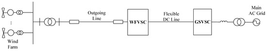
Figure 1.
Wind Farm Grid Connection Through VSC-HVDC System.
Figure 1 illustrates the schematic diagram of a typical wind farm integrated via a VSC-HVDC transmission system. The architecture primarily consists of the following key components:
1. The Wind Farm Cluster: This represents an aggregation of multiple wind turbines, typically Doubly Fed Induction Generators (DFIGs) as studied in this paper, which generate electrical power at a medium voltage level (e.g., 0.69 kV).
2. Step-up Transformers and Collection Grid: The power from individual turbines or groups is collected and stepped up to a higher AC voltage (e.g., 35 kV) through pad-mounted transformers. A collection grid then transmits this consolidated power to the wind farm converter station.
3. WFVSC: This is the sending-end converter station. Its primary function is to rectify the incoming AC power from the wind farm cluster into stable DC power for transmission. To establish a stable voltage and frequency reference for the wind farm, which is inherently a weak grid with limited generation inertia, the WFVSC is typically controlled in a Constant AC Voltage and Frequency (V/f) Control mode. This control strategy maintains the stability of the AC bus voltage (e.g., 230 kV as mentioned in the study) at the sending end, ensuring reliable operation of the wind turbines regardless of grid-side disturbances.
4. DC Transmission Line/Cable: This is the bipolar DC link (±200 kV in this study) that transmits the bulk power over a long distance (500 km in this study) with minimal losses compared to AC transmission.
5. GSVSC: This is the receiving-end converter station. Its primary function is to invert the transmitted DC power back into synchronous AC power suitable for the main grid. The GSVSC is typically controlled in a Constant DC Voltage and Reactive Power (Q) Control mode. The constant DC voltage control is crucial as it maintains the power balance and stability of the entire DC link. Simultaneously, it can provide independent reactive power support to the main AC grid, enhancing voltage stability and fulfilling grid code requirements.
6. Main AC Grid: The ultimate destination of the transmitted power, which is a strong, interconnected network.
Energy Flow Direction:
The power flow follows a unidirectional path (under normal operation) from the wind farm to the main grid: Wind Farm Cluster → Collection Grid & Step-up Transformers → WFVSC (Rectifier) → DC Transmission Line → GSVSC (Inverter) → Main AC Grid.
This system model, particularly the dual weak-infeed characteristics caused by the wind farm’s limited short-circuit capacity and the current-limiting behavior of the VSC-HVDC converters, forms the basis for the subsequent analysis of protection adaptability and fault ride-through coordination.
Line Current Differential Protection is a highly reliable protection scheme in power systems based on Kirchhoff’s Current Law (KCL). Its fundamental principle involves identifying internal and external faults by comparing the vector sum of currents at both ends of the protected line. Specifically, the protection device measures current signals from both line terminals and calculates the differential current and restraining current.
At the sending end, when a fault occurs on the outgoing line, the fault characteristics undergo significant changes due to the weak-infeed nature of both the wind farm side and the flexible DC side. Key features include low fault current magnitude, severe phase deviation, and high harmonic content, which collectively degrade the restraining characteristics of conventional differential protection. This leads to reduced sensitivity and even risk of failure to operate during high-resistance grounding faults.
To address this issue, this paper proposes a novel differential protection scheme that combines variable-based differential protection, steady-state differential protection and zero-sequence differential protection. This integrated approach enhances sensitivity for outgoing lines under dual weak-infeed conditions.
The variable quantity differential protection (Δ differential) is based on the variation in current before and after a fault, calculating the differential current and restraining current. Its operating equation is ΔICDΦ > 0.75ΔIRΦ and ΔICDΦ > IH, where Φ = A, B, C. ΔICDΦ is the variable differential current, and ΔIRΦ is the variable restraining current. When capacitive current compensation is enabled, IH is the larger of “1.5 times the differential current setting value” (set value) and 1.5 times the measured capacitive current. When capacitive current compensation is disabled, IH is the larger of “1.5 times the differential current setting value” (set value) and 4 times the measured capacitive current. The measured capacitive current is obtained from the uncompensated differential current during normal operation.
Steady-state differential protection (full differential) directly compares the current phasors (magnitude and phase) from both ends of the line. Its first-stage operating equation is ICDΦ > 0.6IRΦ and ICDΦ > IH, where Φ = A, B, C. The second-stage operating equation is ICDΦ > 0.6IRΦ and ICDΦ > IZD, where Φ = A, B, C. Here, ICDΦ represents the differential current, and IRΦ denotes the restraining current. When capacitive current compensation is enabled, IZD is taken as the larger value between the “differential current setting” and 1.25 times the measured capacitive current; when capacitive current compensation is disabled, IZD is the larger value between the “differential current setting” and 1.5 times the measured capacitive current. The second stage operates with a time delay.
Both the variable quantity differential protection and steady-state differential protection utilize phase currents and belong to phase current differential protection systems.
Zero-sequence differential protection utilizes the zero-sequence current component generated during a fault to form the differential criterion. Its operating equations are ICD0 > 0.75IR0, ICD0 > IL; and ICDΦ > 0.15IRΦ, ICDΦ > IL, where Φ = A, B, C. Here, ICD0 represents the zero-sequence differential current, and IR0 denotes the zero-sequence restraining current. Regardless of whether capacitive current compensation is enabled or disabled, IL is taken as the larger value between the “differential current setting” and 1.25 times the measured capacitive current. The zero-sequence differential protection operates with a time delay.
The wind farm station and outgoing line model are constructed as shown in Figure 2, where a fault occurs on Line 1 with Relay 1 and Relay 2 (from two different manufacturers) configured at both ends. Both relays adopt an integrated protection scheme combining variable quantity differential protection, steady-state differential protection, and zero-sequence differential protection.
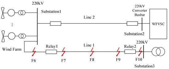
Figure 2.
Model of the wind farm and its outgoing line (red arrow represents fault location).
According to the analysis, when the VSC-HVDC operates in “point-to-point” single-pole layer mode, the converter station contributes the minimum short-circuit current to faults on the outgoing line. Based on the simulation waveforms under no-load conditions on the renewable energy side, the sensitivity of differential protection is verified.
Test Scenario: Under single-pole voltage–frequency control (VF control) at the wind farm converter station with AC bus voltage regulated at 230 kV, and with the renewable energy station operating under no-load conditions, fault simulations were conducted at the 220 kV AC bus of Substation 1 (F6, external zone); the left (F7), middle (F8), and right (F9) sections of Line 1; and the AC bus of the renewable energy station (Substation 3, F10, external zone)—with each fault point testing single-phase metallic ground faults, phase-to-phase metallic faults, phase-to-phase metallic ground faults, and three-phase metallic faults. It is important to note that the fault points F6 through F10 indicated in Figure 2 denote potential fault locations. Each simulation considers a single fault occurring at one of these locations to assess protection performance for both internal and external faults.
The settings for line protection are configured as follows: Relay 1 primary differential operating current setting at 525 A, Relay 2 primary differential operating current setting at 350 A, with both protections having a common primary starting current setting of 200 A.
2.2. Sensitivity Verification Basis and Protection Setting Rationale
Per DL/T 559-2018, the sensitivity of both current variation startup values and zero-sequence current startup values must exceed 4 for metallic faults at the line end. Q/GDW 11425 stipulates that the sensitivity of differential current settings shall be greater than 3 during line-end metallic faults. This section verifies the sensitivity of protection startup values and settings under all types of line-end metallic faults.
In accordance with GB/T 14285, the total fault clearance time for unit protection shall not exceed 20 ms for near-end faults and 30 ms for far-end faults (excluding channel delay). The channel delay for longitudinal differential protection must be within 1 ms.
The steady-state differential Stage 2 time delays are set at 25 ms for Relay 1 and 40 ms for Relay 2. Zero-sequence differential time delays are configured at 40 ms for Relay 1 and 100 ms for Relay 2.
The operating criteria for the integrated differential protection scheme are designed based on a sensitivity–security trade-off analysis, considering the unique weak-infeed characteristics of the VSC-HVDC system. The thresholds must be secure against maximum spurious differential currents during external faults and CT saturation while remaining sensitive to high-resistance internal faults.
Setting Rationale and Robustness Considerations:
1. Setting Rationale:
The operating thresholds were determined via extensive EMT simulations analyzing the trade-off between dependability and security. The slope (e.g., 0.6) was chosen to provide a security margin above the measured spill current during heavy load flow and external faults, while the minimum operating current (IH, IZD) was set above the maximum unbalanced current observed during system energization, CT mismatch (assumed <5%), and harmonic-rich conditions. IH for Variable Quantity Differential: The factor of 1.5 (with compensation) or 4.0 (without compensation) on the measured capacitive current provides a security buffer against line charging current transients and measurement errors. IZD for Steady-State Differential Stage 2: The 1.25/1.5 factor offers a more secure setting for the time-delayed section, accounting for potential long-term slight CT errors and communication phase drift.
2. Robustness:
CT Saturation: The variable quantity differential (Δ) is inherently more resilient to CT saturation caused by external faults, as it uses the change in current from a pre-fault steady state. The harmonic restraint function, a standard feature in modern numerical relays, was enabled in both Relay 1 and 2 to further mitigate maloperation due to saturation-induced harmonics.
Measurement Noise&MMC Harmonics: The protection algorithms employ a full-cycle Fourier filter to extract the fundamental component, effectively suppressing high-frequency switching noise from the MMC (typically >1 kHz) and measurement noise. The minimum operating current IH is set above the peak noise floor observed in the system.
Channel Latency&Jitter: The differential protection algorithm uses a deterministic data synchronization protocol (e.g., IEEE 1588 PTP). The stated operating times (≤30 ms) include a worst-case assumed channel jitter of ±0.5 ms. The restraining current calculation is designed to be robust to minor synchronization errors.
The specific settings for the two relays (from different vendors) used in the simulation are detailed in Table 1.

Table 1.
Differential Protection Settings for Relay Vendors 1 and 2.
2.3. Sensitivity Verification of Differential Protection for Metallic Faults
Based on short-circuit current data from various metallic faults at different locations, statistical sensitivity evaluations were conducted for steady-state differential protection (Stage 2) operating values and zero-sequence differential protection operating values.
All displayed waveforms represent calculated Phase A quantities. Figure 3 and Figure 4 respectively show the simulation waveforms of Relay 1 and Relay 2 during an AN-phase-to-ground fault at location F7.
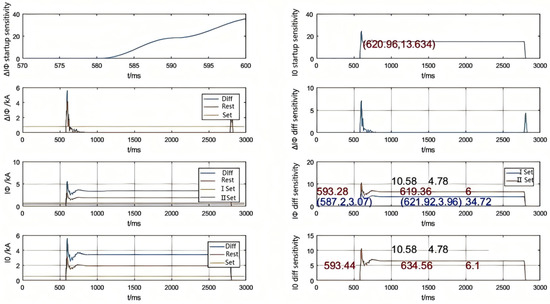
Figure 3.
Relay 1 Sensitivity During AN-Phase-to-Ground Fault at F7 (Variable Quantity + Steady-State + Zero-Sequence Differential Protection).
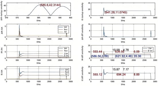
Figure 4.
Relay 2 Sensitivity During AN-Phase-to-Ground Fault at F7 (Variable Quantity + Steady-State + Zero-Sequence Differential Protection).
In the figure, blue numerals indicate (1) time instances when the steady-state differential protection sensitivity exceeds the specified threshold (format: time point, sensitivity value) and (2) time difference between these instances (i.e., duration with sensitivity above threshold, unit: ms). Red numerals represent (1) complete protection operating time window (unit: ms) and (2) minimum sensitivity value within this time window. Black numerals show the maximum and minimum sensitivity values during the entire fault duration.
Table 2.
Minimum sensitivity value during the entire fault process.
Table 3.
Transient variation differential sensitivity time window *.
Table 4.
Minimum sensitivity within the time window of steady-state differential protection and zero-sequence differential protection *.
2.4. Sensitivity Verification of Differential Protection for Faults Through Transition Resistance
Per DL/T 559-2018, for 220 kV transmission lines with 100-ohm fault resistance, (1) zero-sequence current starting element sensitivity ≥ 2.5; (2) current variation starting element sensitivity ≥ 1.5; (3) high-resistance ground zero-sequence differential sensitivity ≥ 1.5; and (4) steady-state differential sensitivity ≥ 1.
This section validates protection sensitivity of starting/operating values for line-end faults with 100-ohm grounding resistance.
Simulation results for F9 faults with 100Ω transition resistance demonstrate that (1) for single-phase-to-ground faults, both protection sets fully satisfy the sensitivity requirements of starting elements (zero-sequence current ≥ 2.5 and current variation ≥ 1.5) and operating elements, and (2) for double-phase-to-ground faults, while current variation starting elements (≥1.5) and phase current differential elements maintain compliance, the zero-sequence starting and differential elements exhibit transient sensitivity degradation below required thresholds (2.5 and 1.5 respectively) during post-fault periods, though steady-state differential currents remain compliant throughout the fault duration.
Simulation results demonstrate that
(1) For all metallic faults within the protection zone, both protection sets exhibit starting-element sensitivity coefficients (Ksen) exceeding 4, fully complying with regulatory requirements.
(2) For all metallic ground faults, the maximum sensitivity values of zero-sequence and steady-state differential protections for both sets remain above 3, satisfying stipulated criteria.
(3) During all metallic faults, the duration with variable-quantity differential sensitivity (Ksen ≥ 3) consistently meets the operating time requirements of both protection sets.
(4) The minimum sensitivity values of zero-sequence and steady-state differential protections for both sets maintain Ksen > 3 across all metallic fault scenarios, ensuring compliance.
(5) No maloperation occurs during external faults.
(6) For single-phase-to-ground faults with 100 Ω transition resistance at the line end, all starting and operating elements of both protection sets fulfill the specified sensitivity requirements.
2.5. Performance Analysis of Differential Protection for Wind Farm Outgoing Lines
Through the adaptability analysis and sensitivity verification of the differential protection at the sending end of the wind farm’s VSC-HVDC transmission system, the following conclusions can be drawn:
- 1.
- Validation of the effectiveness of the protection scheme
The proposed integrated protection scheme combining variable differential protection, steady-state differential protection, and zero-sequence differential protection can still maintain high sensitivity under the weak feed condition of the wind farm, meeting the requirements of standards such as DL/T 559-2018 and Q/GDW 11425.
In the case of metallic faults within the protection zone, the sensitivity of the differential protection is greater than 3 (exceeding 7 in some operating conditions), and the operating time meets the quick-action requirements specified in GB/T 14285 (≤20 ms for near-end faults and ≤30 ms for far-end faults).
The steady-state differential protection has slightly lower sensitivity (minimum 2.56) in symmetric faults (such as three-phase short circuits) and needs to rely on the variable differential protection as a supplement.
- 2.
- Adaptability to high-resistance faults
For single-phase grounding faults with a 100Ω transition resistance, both the protection starting and operating elements meet the sensitivity requirements (zero-sequence starting > 2.5, variable starting > 1.5).
In the case of two-phase grounding high-resistance faults, the zero-sequence-related criteria (starting and differential) have a brief phenomenon of insufficient sensitivity, but the phase current differential protection still operates reliably, which needs to be further optimized by combining with the auxiliary criteria of waveform characteristics.
3. Research on Coordinated Control Strategy for FRT of Receiving-End VSC-HVDC Lines
The key to achieving FRT in a VSC-HVDC wind power grid-connected system is to maintain the balance of VSC-HVDC transmission power. The coordinated control strategy for FRT refers to the approach where, during a grid fault, while activating the self-regulating unloading circuit, the system simultaneously reduces the power transmitted from the wind farm to the VSC-HVDC circuit through MPPT of the doubly fed wind farm. By implementing coordinated control using two improved schemes, the system can achieve smooth FRT.
3.1. Protection Control of Self-Regulating Unloading Circuit
Traditional unloading circuits usually require a large number of switching devices to be connected in series. Considering the static and dynamic voltage sharing issues when IGBT switching devices are connected in series, their implementation in practical engineering is greatly restricted. In addition, the problem of power fluctuation caused by the pulse control mode seriously affects the FRT effect.
To this end, this paper proposes a self-regulating unloading circuit protection control, whose topological structure and control principle are shown in Figure 5. This method divides the traditional DC unloading resistor into multiple identical sub-modules (SMs), which are composed of n sub-modules in parallel [28]. The resistance capacity of each sub-module is only 1/n of that of the traditional unloading resistor, and each sub-module can be switched on and off independently. When the IGBT in a sub-module is turned on, the resistor of that sub-module is put into operation and consumes active power. By controlling the number of sub-modules put into operation, the power consumed by the unloading circuit can be continuously adjusted, achieving relatively smooth operating characteristics. This makes it easy to adapt to faults of various degrees, and at the same time, it can avoid the direct series connection of switching devices. In summary, the circuit in Figure 5 enables adaptive energy dissipation by dynamically switching in the required number of resistor modules based on the real-time power imbalance, thus providing a more flexible and economical solution compared to a fixed full-capacity resistor.
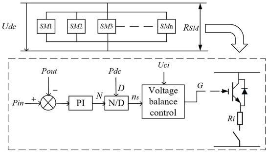
Figure 5.
Self-regulating unloading resistance control diagram.
The principle for selecting resistors in the sub-modules remains unchanged. The main difference is that the original centralized resistor is distributed among n modules. The calculated resistance value for each sub-module is
where n is the number of sub-modules, Udcmax is the control value of the DC side voltage during the fault period. ΔPdc is the maximum active power difference transmitted by the balanced VSC-HVDC system.
Therefore, the power that each sub-module can independently absorb when it is turned on is
When the DC voltage exceeds the designed threshold value Udc_h, the unloading circuit is triggered to turn on. Differences in the severity of faults will lead to different power deficits, with a corresponding number of ns (1 ≤ ns ≤ N) modules put into operation. Pin represents the input power from the DC side to the AC side, Pout is the output power of the converter station on the AC side, and Pdc is the rated transmission power of the DC system. The number of sub-modules ns to be put into operation corresponding to the actual power deficit is calculated as shown in Equation (3).
The self-regulating unloading circuit offers the advantage of calculating the number of sub-modules required for operation based on the real-time power deficit. Therefore, compared with the traditional unloading circuit, for fault conditions that only require consuming a small power deficit, there is no need to install a capacity matching the output power of the wind farm [29]. Moreover, the sub-modules that are not put into operation do not require cooling, which greatly reduces the cost.
3.2. FRT Coordinated Control Strategy
If only the unloading circuit is used under the fault of the receiving-end AC grid, although FRT can be achieved, the resistance components must be designed according to the most severe fault conditions. This brings problems of cost and land occupation, lacking practicality. This paper proposes a FRT coordinated control strategy that combines the method of putting into the self-regulating unloading circuit with the method of reducing the transmitted power by tracking the maximum power of the wind farm. Through MPPT of the doubly fed wind farm, the active power transmitted from the wind farm to the flexible DC transmission circuit is reduced, thereby reducing the energy that needs to be consumed by the self-regulating unloading circuit. It effectively exerts the advantages of both and has greater potential for practical application.
The structural diagram of double-fed wind farm integration with VSC-HVDC is shown in Figure 6. The wind farm is connected to the step-up transformer via a transmission line, and then stepped up to the sending end of the flexible DC transmission system. The flexible DC transmission system transmits power to its receiving-end grid through the DC line. The unloading circuit is connected in parallel to the high-voltage DC bus on the DC side in the form of a high-voltage load in the DC link [30].
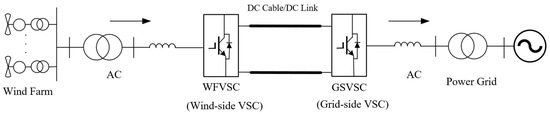
Figure 6.
The system structure of double-fed wind farm integration with VSC-HVDC.
When a fault occurs on the grid side and the DC voltage exceeds the designed threshold Udc_h, the overpower value ΔPs of each sub-module is
where UsIrec is the receiving-end power measured at the outlet of each sub-module circuit, and UsIsend is the sending-end power measured at the inlet of each sub-module circuit. The difference between the two is the overpower value.
At this point, since communication itself has a certain delay, if the load reduction is implemented only through MPPT within a short period, it will cause a certain delay. The use of the unloading circuit in this coordinated strategy avoids this problem.
The process of the FRT coordinated control strategy can be divided into three stages:
- (1)
- The first stage (t < ts):
Considering the issue of communication delay at the initial stage of a fault, the coordinated control strategy uses the unloading circuit to control power consumption within a short period after the fault occurs. Let t be the moment when the fault occurs, and ts be the moment when the wind farm receives the load reduction command. At this time, the number of sub-modules to be put into operation is calculated as
where ΔP1 is the power deficit consumed when MPPT is not triggered.
- (2)
- The second stage (ts < t< tfin):
At this point, for the DFIG, the following relationship holds [31]:
where Ps is the active power output from the stator of DFIG; Pe, Pcus, Pfes are the electromagnetic power, stator copper loss, and stator iron loss of DFIG; Pm is the input mechanical power of DFIG; P′m is the mechanical loss power of DFIG; Pmec is the net mechanical power absorbed by DFIG; and tfin is the moment when the wind farm reaches a new power balance.
To achieve maximum power point tracking of the wind turbine, the active power command output by the generator can be calculated in real-time based on the optimal power curve of the wind turbine and the rotational speed of the wind turbine, as follows [32,33]:
The active power command Psref, derived from Equation (7), is then used to control the DFIG’s active output, thereby achieving maximum wind energy tracking.
When the wind farm receives the fault signal command, it starts to operate with active power de-loading. If the power de-loading amount at this time is ΔPsref, and ΔP2 is the power deficit consumed by the fault when the maximum power de-loading operation is triggered but the power balance has not been achieved, ns2 the number of sub-modules put into operation at this time is
where is the slope of the active power de-loading curve of the wind turbine during the fault, and T is the time required for the wind farm to reach a new power balance.
- (3)
- The third stage (t > tfin):
When the wind farm reaches a new power balance, there is no longer a need to put the unloading circuit into operation at this point. The FRT can be fully achieved by the control strategy, and the ride-through effect is more stable. ΔP3 is the power deficit consumed by the fault after the wind farm reaches a new power balance.
where Psref′ is the active power output of the wind farm after it reaches a new power balance.
In summary, the FRT coordination process can be divided into three stages, and the total power consumed in each fault stage is
Figure 7 shows the schematic diagram of the system’s FRT coordinated control strategy under grid faults. During the normal operation of the power grid, the DC voltage does not exceed the threshold Udc_h, the output of the logic judgment module is S = 0, and the active power control of the wind farm adopts the traditional maximum wind energy tracking control mode.
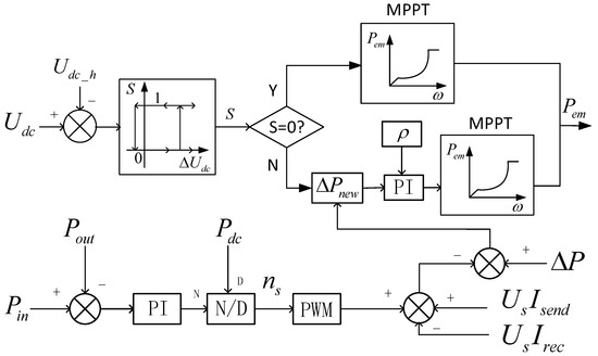
Figure 7.
Principle diagram of FRT coordination.
If a fault occurs on the AC side of the system and the DC bus voltage exceeds the threshold, the output value of the logic judgment module is S = 1, thereby activating the fault coordinated control strategy. While putting the self-regulating unloading resistor into operation, the MPPT active power de-loading of the wind farm is used for control. Figure 8 shows the coordinated control of the wind farm under fault conditions. The blue dashed box in the lower right corner of Figure 8 represents the coordinated control strategy.
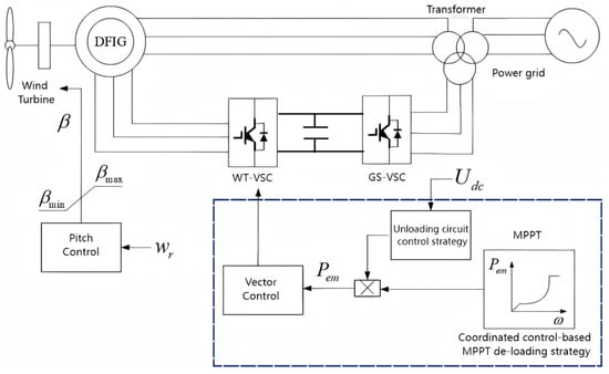
Figure 8.
Coordinated control of wind farm under fault.
In the case of grid faults, by improving the original tracking curve of the wind farm, the electromagnetic torque of the DFIG is reduced, thereby the active power output of the wind farm drop rapidly. When cooperating with the self-regulating unloading resistor, since part of the power deficit is dissipated as heat energy by the unloading resistor, it will not cause a significant increase in the rotational speed of the wind turbine, nor will it bring about problems in the stable control of the wind turbine, thus being able to well protect the wind turbine. To realize MPPT power de-loading control for each DFIG in the wind farm during faults, a corresponding fast communication system is necessary. In this way, during the grid fault and recovery process, the implementation of power de-loading and de-loading recovery control can be carried out according to the operating status of the DC bus voltage.
3.3. Simulation Verification
To verify the effectiveness of the FRT coordinated control strategy, a model was built and verified in PSCAD.
DFIG Parameters: Rated power 5 MW, Rated voltage 0.69 kV, Rated frequency 50 Hz, Stator resistance 0.0054 p.u., Rotor resistance 0.0061 p.u., Stator self-inductance 0.10 p.u., Rotor self-inductance 0.11 p.u.
VSC-HVDC System Parameters: Rated DC voltage ± 200 kV, Rated DC current 0.5 kA, Rated converter capacity 500 MVA, Rated transmitted active power 200 MW, DC line length 500 km.
The rated power of a single DFIG is 5 MW, and the wind farm is composed of 40 equivalent DFIG. In the model, a self-regulating unloading circuit is added to the VSC-HVDC system part, and the DC voltage threshold is set to 1.05 p.u.
To verify the correctness of the FRT coordinated control strategy, an instantaneous three-phase short-circuit fault occurs on the AC grid side of the receiving end at 4 s, with the fault lasting for 0.625 s. The grid voltage drops to 0.2 p.u. as shown in Figure 9 below, and the fault is cleared at 4.625 s. To verify the effectiveness of the control strategy, the simulation results ignore the start-up process of the converter station.
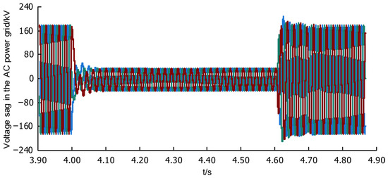
Figure 9.
Grid voltage dip.
Figure 9 shows that the receiving-end grid voltage drops to approximately 20% at 4 s. Figure 10 shows the FRT achieved only by the traditional unloading circuit. It can be observed that during the fault duration, the DC bus voltage of the VSC-HVDC system is continuously controlled by the power consumed by the unloading resistor.
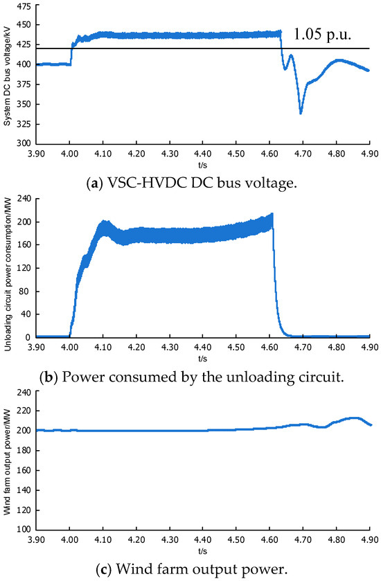
Figure 10.
FRT operation of traditional unloading circuit.
In Figure 10, the unloading circuit maintains high-power operation throughout the fault period, which requires the cooling equipment to operate simultaneously, resulting in high cost requirements. Figure 10c shows that without a control strategy, the wind farm’s output power remains unchanged, causing the system’s DC voltage to remain continuously high. According to the principle of power conservation, the output power of a wind farm is always equal to the sum of the power consumed by the unloading circuit and the power of the GSVSC.
Under the FRT coordinated control strategy, it can be seen from Figure 11a that the voltage of the VSC-HVDC system will rise partially at the initial stage of the fault. However, after the MPPT de-loading is incorporated, the voltage can basically remain stable at the level during the non-fault period. Compared with the method using only the traditional unloading circuit, the stability of FRT is significantly improved.
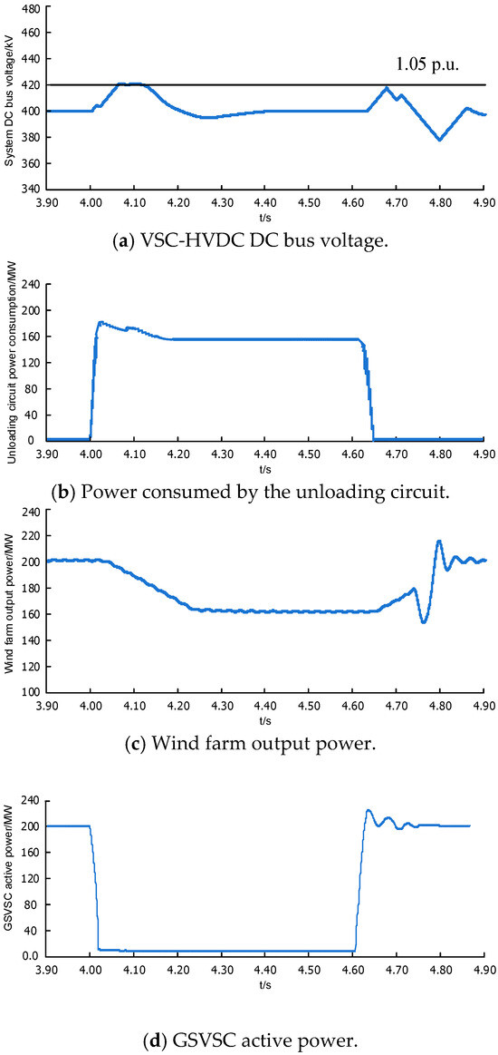
Figure 11.
Operation of FRT coordinated control.
It can be seen from Figure 11d that the power output capacity of GSVSC decreases, and under the condition of deep voltage drop, the transmitted power is basically zero, which will cause system power imbalance. In Figure 11c, the output power of the wind farm operates in a de-loading mode under MPPT control. When a fault occurs, due to the transmission speed issue of the communication system, the wind farm cannot receive the de-loading command immediately, which is also verified by the simulation results. However, at this time, the self-regulating resistor can be put into operation for energy consumption, which balances the power deficit in the initial stage of the fault and makes up for the deficiency. In Figure 11b, the required capacity of unloading circuit is much smaller than that required by the traditional method during the fault period, which verifies the advantages of the FRT coordinated control strategy.
Under the FRT coordinated control strategy, the DC bus voltage of the VSC-HVDC will not exceed the set threshold. At the moment a fault occurs, the self-regulating unloading resistor is put into operation, and at the same time, the output power of DFIG is curtailed. When the wind farm achieves the maximization of MPPT control, it can be seen from Figure 11a that the DC bus voltage is more stable than when only the unloading resistor is put into use, which verifies the superiority of this FRT coordinated control strategy.
3.4. Analysis of FRT Control Strategy for Flexible DC Lines at the Receiving End
Aiming at the FRT problem of wind farms connected to the grid via flexible DC transmission systems, an innovative coordinated control strategy is proposed, which combines modular self-regulating unloading resistors with MPPT de-loading control of DFIG. Through a three-stage coordinated control mechanism (unloading-dominated → transitional collaboration → pure de-loading operation), it effectively addresses issues such as excessive equipment capacity, high costs, and slow dynamic response in traditional schemes. Simulation results show that under severe faults where grid voltage drops to 20%, this strategy can control the DC bus voltage fluctuation within 1.05 p.u., shorten the operation time of the unloading circuit by more than 60%, and avoid unit instability by curtailing wind farm output by 30–50%. This scheme not only significantly improves the stability and economy of FRT but also provides a feasible technical solution for high-proportion new energy grid-connected systems.
3.5. Comparative Analysis with Related Work
To more clearly illustrate the innovations and advantages of this study, the proposed protection and FRT coordination control scheme is compared with existing related research, as summarized in Table 5.
Table 5.
Comparative Analysis of Related Research Work.
Table 5.
Comparative Analysis of Related Research Work.
| Literature | Protection Scheme Type | FRT Strategy | Weak-Infeed Resistance | Sensitivity (Min) | DC Voltage Control (p.u.) | Coordination Mechanism/ Timing | Remarks |
|---|---|---|---|---|---|---|---|
| [14] | Sequence Component Assisted Differential | None | Medium | — | — | None | Improves sensitivity for ground faults |
| [15] | Traditional Differential + Simulation Analysis | None | Low | — | — | None | MMC leads to reduced sensitivity |
| [16] | Single-Ended Protection Based on Transient Waveforms | None | Medium | — | — | None | Requires high sampling rate |
| [17] | Single-Ended Branch Coefficient Based Protection | None | Medium | — | — | None | High-impedance fault identification |
| [18] | High-Frequency Distance Protection | None | Medium | — | — | None | Avoids control strategy influence |
| [21,22] | None | Dynamic Unloading Resistor | — | — | 1.10–1.15 | No Coordination | Large capacity, high cost |
| [23,24,25] | None | Frequency/Inertia Support, Power Reduction Control | — | — | 1.08–1.12 | No Coordination | Stringent response time requirements |
| This Paper | Increment + Steady-State + Zero-Sequence Differential | Self-Regulating Resistor + MPPT Power Reduction | High | ≥3.0 | ≤1.05 | Three-Stage Coordination | Sensitivity time window analysis, modular resistors, combined control |
The comparison reveals that the main advantages and net improvements of this research are:
1. Differential Protection Performance: The proposed integrated differential protection scheme maintains high sensitivity under wind farm weak-infeed conditions. The minimum sensitivity for internal metallic faults is ≥3.0 (median > 4.0, 95th percentile > 6.0), significantly outperforming traditional schemes. Detailed sensitivity time window analysis is provided.
2. FRT Economy and Smoothness: The proposed hierarchical coordinated strategy of “Self-Regulating Resistor + MPPT Power Reduction” controls the DC voltage fluctuation within ≤1.05 p.u. This represents a reduction in voltage overshoot of approximately 5–10% compared to using only unloading resistors (1.10–1.15 p.u.) or only control strategies (1.08–1.12 p.u.), resulting in a smoother FRT process.
3. Innovative Coordination Mechanism: The three-stage coordinated control balances the capacity of unloading equipment with dynamic response speed. The modular design of the self-regulating resistor reduces the required capacity by more than 60% compared to traditional schemes, offering both economy and practicality.
4. Conclusions and Prospects
Aiming at the fault impact problem faced by large-scale wind farms in long-distance transmission via flexible DC transmission systems, this study proposes a collaborative solution of protection adaptability and FRT coordinated control. Through theoretical analysis, model construction, and simulation verification, the main conclusions are as follows.
In terms of protection adaptability, a new protection scheme integrating variable quantity differential protection, steady-state quantity differential protection, and zero-sequence differential protection is proposed, which effectively solves the problem of reduced sensitivity of traditional differential protection caused by the weak feed characteristics in the flexible DC transmission system of wind farms. By establishing a refined wind farm model containing a flexible DC system, the adaptability of the differential protection for the outgoing line is checked. Simulation results show that under metallic faults within the protection zone, the sensitivity of differential protection is better than 3.0, and it reliably does not operate for external faults; meanwhile, the protection sensitivity meets the requirements of regulations during faults with transition resistors, verifying the reliability of differential protection in flexible DC-connected systems.
In terms of FRT control, an innovative hierarchical coordinated control strategy of “self-regulating unloading circuit + wind farm MPPT de-loading” is proposed. Through dynamic switching of resistor modules and wind farm power adjustment, this strategy controls the DC voltage fluctuation within 1.05 p.u., featuring both rapid response and stable ride-through characteristics, which significantly improves the economy and feasibility of the system.
Advantages of coordinated control: Compared with traditional single schemes, the joint control strategy uses unloading resistors to quickly suppress voltage fluctuations in the initial stage of faults, gaining time for wind farm de-loading; subsequently, it gradually reduces the power deficit through MPPT de-loading, reduces the demand for resistor capacity, and realizes a smooth transition during the FRT process.
Although certain achievements have been made in this study, further exploration is still needed in the following directions:
Research on multi-scenario adaptability: The current research mainly focuses on typical fault conditions. In the future, it can be extended to more complex grid faults (such as multi-terminal flexible DC systems, hybrid AC/DC faults, etc.) to verify the universality of the coordinated control strategy.
Optimization of dynamic response: Further optimize the dynamic coordination mechanism between self-regulating resistors and MPPT de-loading, reduce the impact of communication delay on control effects, and improve the robustness of the system under extreme faults.
In summary, this study provides theoretical support and technical references for the reliable operation of wind farms connected to the grid via flexible DC systems. In the future, through interdisciplinary integration and engineering practice, it is expected to further enhance new energy absorption capacity and power grid stability.
Author Contributions
Conceptualization, H.W. and W.Z.; methodology, H.W.; software, Y.L.; validation, H.W., W.Z. and Y.L.; writing—original draft preparation, Y.L.; writing—review and editing, H.W.; visualization, W.Z.; supervision, Hao Wang; project administration, H.W.; funding acquisition, H.W. All authors have read and agreed to the published version of the manuscript.
Funding
This work was supported in part by the Science and Technology Project of State Grid Sichuan Electric Power Company under Grant 521997230003.
Data Availability Statement
The original contributions presented in this study are included in the article material. Further inquiries can be directed to the corresponding author.
Conflicts of Interest
The authors declare no conflicts of interest.
References
- Xia, Y. 2024 Global Newly Grid-connected Offshore Wind Power Capacity Reaches 8GW. In Wind Energy; GWEC: Brussels, Belgium, 2025; pp. 52–54. [Google Scholar]
- Lin, J.; Li, L.; Wu, N. Current Status and Prospects of International Renewable Energy Development. In Report on the Development of International Clean Energy Industry; International Clean Energy Forum: Macau, China, 2019. [Google Scholar]
- Xu, L.; Yao, L.; Sasse, C. Grid integration of large DFIG-based wind farms using VSC transmission. IEEE Trans. Power Syst. 2007, 22, 976–984. [Google Scholar] [CrossRef]
- Rao, H.; Huang, W.; Guo, Z.; Zhou, Y. Practical experience of VSC-HVDC transmission in large grid. High Volt. Eng. 2022, 48, 3347–3355. [Google Scholar]
- Lin, S. Application Design of VSC-HVDC Technology in Large-Scale Offshore Wind Power. Lamps Light. 2025, 1, 228–230. [Google Scholar]
- Fan, X.; Chi, Y.; Ma, S. Research and Application of Key Technologies and Technical Standards for Large-Scale Offshore Wind Power Integration into the Power Grid. Power Syst. Technol. 2022, 46, 2859–2870. [Google Scholar]
- Adili, B.; Fan, Y.; Wang, M. Modeling and simulation of relay protection strategy for large-scale wind power access. Electron. Des. Eng. 2023, 31, 171–175. [Google Scholar]
- Li, J.; Zheng, T.; Zhao, Y. Impact of doublyfed wind system short-circuit current characteristics on the transmission line distance protection. Power Syst. Prot. Control 2017, 45, 37–47. [Google Scholar]
- Li, Y.; Sun, Z.; Zhang, Z. Impact of Large-Scale Concentrated Integration of Wind Turbines on System Short-Circuit Current. Electr. Power 2018, 51, 33–38. [Google Scholar]
- Song, G.; Tao, R.; Li, B.; Hu, J.; Wang, C. Survey of fault analysis and protection for power system with large scale power electronic equipment. Autom. Electr. Power Syst. 2017, 41, 2–12. [Google Scholar]
- Shi, B.; Sun, G.; Jin, R.; Xie, J.; Wang, Y. Influence Study of VSC-HVDC Interconnection on AC Line Differential Protection. In Proceedings of the 2019 IEEE 8th International Conference on Advanced Power System Automation and Protection (APAP), Xi’an, China, 21–24 October 2019. [Google Scholar]
- Liu, H.; Jia, K.; Bi, T.; Niu, H.; Li, W. Low Voltage Ride Through Methods for Flexible DC Converter Stations Connected to the Gathering System of New Energy Base. Trans. China Electrotech. Soc. 2025, 40, 759–770. [Google Scholar]
- Aluko, A.O.; Akindeji, K.T. Mitigation of Low Voltage Contingency of Doubly FED Induction Generator Wind Farm Using Static Synchronous Compensator in South Africa. In Proceedings of the 2018 IEEE PES/IAS PowerAfrica, Cape Town, South Africa, 28–29 June 2018. [Google Scholar]
- Lai, Y.; Wang, Z.; Wang, T. Adaptability analysis of current differential protection in an AC power grid with an MMC-HVDC and improvement measures. Power Syst. Prot. Control 2023, 51, 145–154. [Google Scholar]
- Xiao, C.; Han, W.; Li, Q.; Xiong, X. Adaptability of MMC-HVDC System on Relay Protection of AC Transmission Lines. Smart Power 2020, 48, 1–8. [Google Scholar]
- Zheng, T.; Chen, Y. Single Terminal Protection for Flexible DC Transmission Lines Based on Transient Current Waveform Characteristics. Power Syst. Technol. 2025, 49, 3522–3532. [Google Scholar] [CrossRef]
- Shu, H.; Ren, M.; Tian, X.; Li, T. Line Protection Scheme for Four-terminal Flexible Direct Loop Network Based on Single-terminal Branch Coefficient. High Volt. Eng. 2024, 50, 683–692. [Google Scholar]
- Gao, Y. Analysis of Relay Protection Applicability of AC-DC Hybrid Distribution Network. Master’s Thesis, Inner Mongolia University of Technology, Hohhot, China, 2021. [Google Scholar]
- Li, G.; Xu, Y.; Jiang, S. Coordinated control strategy for receiving-end AC fault ride-through of an MMC-HVDC connecting offshore wind power. Power Syst. Prot. Control 2022, 50, 111–119. [Google Scholar]
- Yang, R.; Wang, X.; Chen, Q. Fault ride-through method of flexible HVDC transmission system for wind farm integration based on coordination of wind turbines and distributed braking resistors. Autom. Electr. Power Syst. 2021, 45, 103–111. [Google Scholar]
- Cheng, M.; Du, H. Research on simulation model of Fault-Crossing control strategy for VSC-HVDC. Electr. Switch 2016, 54, 27–29+33. [Google Scholar]
- Wang, G.; Jia, Y.; Deng, N.; Arman, H. AC Fault-Crossing scheme for main network side of VSC-HVDC system for offshore wind power access. Glob. Energy Internet 2019, 2, 146–154. [Google Scholar]
- Erlich, I.; Feltes, C.; Shewarega, F. Enhanced voltage drop control by VSC-HVDC systems for improving wind farm fault ride through capability. IEEE Trans. Power Deliv. 2014, 29, 378–385. [Google Scholar] [CrossRef]
- Han, X.; Wang, Y.; Zhang, Z. Research on Fault Traverse Capability of Wind Farm Based on VSC-HVDC Networking. Power Sci. Eng. 2014, 30, 26–31. [Google Scholar]
- Wang, Y.; Fu, Y.; Su, X.; Liu, J.; Luo, Y. Research on Fault Traverse Control Strategy of Wind Farm Based on VSC-HVDC Network. J. Electr. Technol. 2013, 28, 150–159. [Google Scholar]
- Tehrani, K.; Beikbabaei, M.; Mehrizi-Sani, A.; Jamshidi, M. A smart multiphysics approach for wind turbines design in industry 5.0. J. Ind. Inf. Integr. 2024, 42, 100704. [Google Scholar] [CrossRef]
- Naik, S.; Koley, E. Fault Detection and Classification scheme using KNN for AC/HVDC Transmission Lines. In Proceedings of the 2019 International Conference on Communication and Electronics Systems (ICCES), Coimbatore, India, 17–19 July 2019. [Google Scholar]
- Li, Q.; Song, Q.; Liu, W. A coordinated control strategy for fault ride-through of wind farm integration based on VSC-HVDC. Power Syst. Technol. 2014, 38, 1739–1745. [Google Scholar]
- Li, X.; Song, Q.; Liu, W. Impact of fault ride through methods on wind power generators in a VSC-HVDC system. Autom. Electr. Power Syst. 2015, 39, 31–36. [Google Scholar]
- Wang, Y.; Zheng, Z.; Li, Y. Review of topology and control application of medium and high voltage power electronic transformer. Adv. Technol. Electr. Eng. Energy 2017, 36, 1–10. [Google Scholar]
- Tang, L.; Shen, C.; Zhang, X. Impact of largescale wind power centralized integration on transient angle stability of power systems: Part Ⅰ: Theoretical foundation. Proc. CSEE 2015, 35, 3832–3842. [Google Scholar]
- Mao, J.; Wu, B.; Wu, A. Adaptive robust MPPT control for wind power generation system. Power Syst. Prot. Control 2018, 46, 80–86. [Google Scholar]
- Chaibi, Y.; Allouhi, A.; Salhi, M. Annual performance analysis of different maximum power point tracking techniques used in photovoltaic systems. Prot. Control Mod. Power Syst. 2019, 4, 171–180. [Google Scholar] [CrossRef]
Disclaimer/Publisher’s Note: The statements, opinions and data contained in all publications are solely those of the individual author(s) and contributor(s) and not of MDPI and/or the editor(s). MDPI and/or the editor(s) disclaim responsibility for any injury to people or property resulting from any ideas, methods, instructions or products referred to in the content. |
© 2025 by the authors. Licensee MDPI, Basel, Switzerland. This article is an open access article distributed under the terms and conditions of the Creative Commons Attribution (CC BY) license (https://creativecommons.org/licenses/by/4.0/).