Abstract
Energy storage systems (ESSs) and active power filters (APFs) are key power electronic technologies for FACTS (Flexible AC Transmission Lines). Battery energy storage has a structure similar to a shunt active power filter, i.e., a storage element and a voltage source inverter (VSI) connected to the grid using a PWM filter and/or transformer. This similarity allows for the design of an ESS with the ability to operate as a shunt APF. One of the key milestones in ESS or APF development is the DC-link design. The proper choice of the capacitance of the DC-link capacitors and their equivalent resistance ensures the proper operation of the whole power electronic system. In this article, it is proposed to estimate the required minimum DC-link capacitance using a spectral analysis of the DC-link current for different operating modes, battery charge mode and harmonic compensation mode, for a nonlinear load. It was found that the AC component of the DC-link current is shared between the DC-link capacitors and the rest of the DC stage, including the battery. This relation is described analytically. The main advantage of the proposed approach is its universality, as it only requires calculating the harmonic spectrum using the switching functions. This approach is demonstrated for DC-link capacitor estimation in two-level and three-level NPC inverter topologies. Moreover, an analysis of the AC current component distribution between the DC-link capacitors and the other elements of the DC-link stage was carried out. This part of the analysis is especially important for battery energy storage systems. The obtained results were verified using a simulation model.
1. Introduction
During the previous decades, power quality and the reliability of a power supply have become some of the most widespread trends in energetics and power electronics [1,2]. On the one hand, the rapid development of the semiconductor industry and microelectronics in this century has led to the growth of nonlinear loads in power grids. On the other hand, it has enabled the rapid development of power electronics, smart grids, and flexible AC transmission lines (FACTS). Particularly, shunt active power filters (APFs) have become an intrinsic part of FACTS and smart grids [3,4,5,6,7]. A shunt APF allows for unity power factor operation even for a nonlinear load with a non-sinusoidal input current [8].
Another power system is the energy storage system (ESS). An ESS allows for energy to be stored in some form and later released as electrical energy when needed. Typically, ESSs are used for many different purposes, such as load leveling, uninterruptible power supply, and peak shaving [9,10,11]. Both APFs and ESSs may have very similar structures: a power converter and a storage element. That is why some types of ESSs may operate exactly as an APF [12,13,14,15,16,17]. The combination of ESSs and APFs provides wide functionality for power quality and uninterruptible power supply within a single power electronic system [18]. Battery energy storage, for example, has the same structure as a shunt APF: a storage element in the DC link, a voltage source inverter, a PWM filter, and a transformer.
The described power electronic systems require accurate calculation of all passive components. In particular, DC-link capacitance must be chosen wisely to ensure that the ESS or APF has enough stored energy for normal operation while not being excessively large, which would make the system unnecessarily expensive.
Several methods for estimating DC-link capacitance in APFs and ESSs have been proposed in the literature [19,20,21,22,23,24]. In [19], the authors derive equations for DC-link capacitance and voltage for an APF, assuming that the APF phase current varies sinusoidally with a magnitude corresponding to the non-active power to be compensated. Additionally, their method assumes that, for a three-phase APF, the AC component at the DC-link has a frequency six times that of the fundamental. The authors use an overload factor to increase this equivalent current, but do not describe a method for defining this factor. Nevertheless, the formula in [19] provides an analytical definition of DC-link capacitance based on the APF power and grid voltage. In [20], a simple fundamental equation is used to define DC-link capacitance. This usage of this equation meets some obstacles in practice, for example, the number of cycles needed to transfer the required amount of energy in transients or the exact energy amount or transfer duration. Furthermore, in this and previous methods, DC-link capacitance is tied to the DC-link voltage. The issue with energy storage systems is that this voltage normally varies widely depending on the battery’s state of charge. Calculations based on worst-case parameters typically give an oversized value. The authors of [21] use a similar approach. Four different methods for estimating DC-link capacitance can be found in [22,23]. The first and second are similar to those described in [20,21]. The third estimates capacitance based on double DC voltage ripple when load unbalance occurs. The fourth approach is more applicable for APFs under harmonic compensation conditions, using the first two higher harmonics of the nonlinear load. Most of the proposed methods in the literature assume that an active filter uses conventional two-level inverters. However, multiple solutions for APFs and ESSs based on multilevel topologies currently exist. Unfortunately, little attention has been given to analyzing DC-link currents in multilevel converters [24,25,26,27]. In [24], the authors analyze the DC-link currents in cascaded and neutral point-clamped three-level inverters, deriving the RMS values of the DC-link current and capacitance current. However, these equations are only applicable for sinusoidal input currents. This method involves integrating power switch currents, which becomes unreasonably complicated if the inverter input current contains higher harmonics. An alternative approach is presented in [25,26], leveraging the tangency between DC-link capacitor voltages and instantaneous AC voltage values to determine the minimum DC-link capacitor voltage required to provide the inverter functionality with a unity power factor [25] or with an arbitrary power factor [26]. While it is attractive for its simplicity, this method has limitations, as it is specifically designed for three-level three-phase inverters using sine-triangle PWM without zero-sequence component injection. Moreover, the main goal of this research is to set the lower limit for DC-link capacitance, making the inverter operate properly. In [27], a general analytical method is introduced to calculate DC-link current harmonics independently of the PWM technique and load current spectrum. This method is a powerful tool and takes account of the PMW harmonics. However, it relies on Bessel functions and convolution integrals, making calculations complex. In addition, an analysis of the DC-link currents requires the consideration of impedance of the circuits behind the DC-link capacitors. In particular, the whole DC-link stage may contain series inductor to limit the battery current, protective capacitors, battery impedance, etc.
In this paper, an alternative approach is proposed for calculating DC-link currents in voltage source inverters. The proposed method is based on the switching functions and spectral analysis. The main advantages are as follows: there is no need to write and solve differential equations, enabling analysis of more complex inverter topologies; its universality, as it can be applied to most inverter topologies; and its compatibility with sine-triangle PWM (with or without zero-sequence component injection), as well as space vector PWM. To illustrate the core idea of DC-link current calculation under different operating conditions, an ESS with the ability to operate as an APF is considered. To highlight the universality of the proposed approach, two-level and NPC three-level inverter topologies are analyzed. Moreover, the analysis of the AC current component distribution between DC-link capacitors and other elements of the DC-link stage was carried out.
The paper is organized as follows: Section 2 provides a short system description; Section 3 describes the DC-link current calculation when an ESS is in battery charging mode; Section 4 describes DC-link current calculation when the ESS supplies a nonlinear load, including current sharing between DC-link capacitors and the rest DC-stage; Section 5 presents the model description and simulation results.
2. System Description
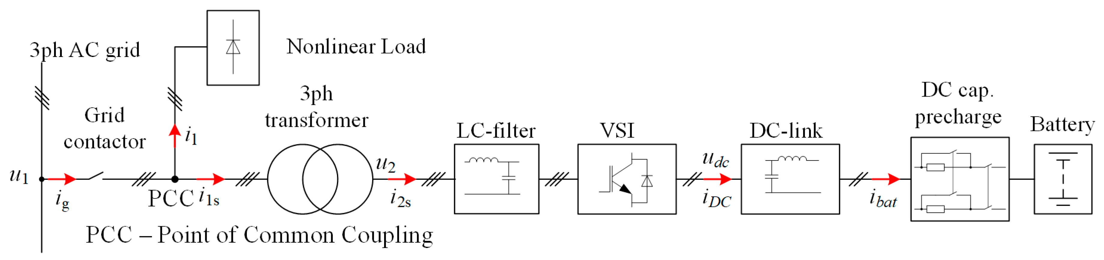
The energy storage system with the active power filter, AC-grid, and nonlinear load are presented in Figure 1.
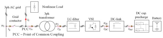
Figure 1.
Power system including an ESS with an APF and the load.
As an example of a nonlinear load, a diode rectifier with an RL-load is considered. The ESS is linked with the grid through a three-phase transformer with Y/Y configuration with a turns ratio , where and are the number of the turns in the primary and secondary winding, respectively. The energy storage system contains the input transformer, an LC-filter, voltage source inverter (VSI), DC-link capacitive filter, DC-link capacitor pre-charge circuit, and the battery. This circuit provides current limitation when the DC-link capacitor is charging from the battery. ESS also contains a contactor at the grid side to provide the offline operation of ESS.
The energy storage system operates in different modes: battery charging mode, parallel mode, and offline mode. In charging mode, ESS operates as an active rectifier: it consumes the sinusoidal current from the grid in phase with the voltage. In parallel mode, the load can be supplied from both the grid and ESS. In particular, if the load consumes the power lower than the ESS-rated power, there is no power consumption from the grid; if the load consumes the power that is more than the ESS-rated power, the difference is consumed from the grid. In addition, ESS prevents the load from the harmonics consumption from the grid. This feature is critically important from the electromagnetic compatibility point of view. It is enough to imagine the current being consumed from the grid if ESS would provide only the active power. In this case, the grid would give only harmonics and the reactive power.
Two operating modes are to be analyzed:
- (1)
- Sinusoidal operation mode: ESS charges the battery and the VSI operates as an active rectifier with sinusoidal line current in phase with the grid voltage.
- (2)
- Harmonic compensation mode: ESS generates non-sinusoidal line current to compensate the load current.
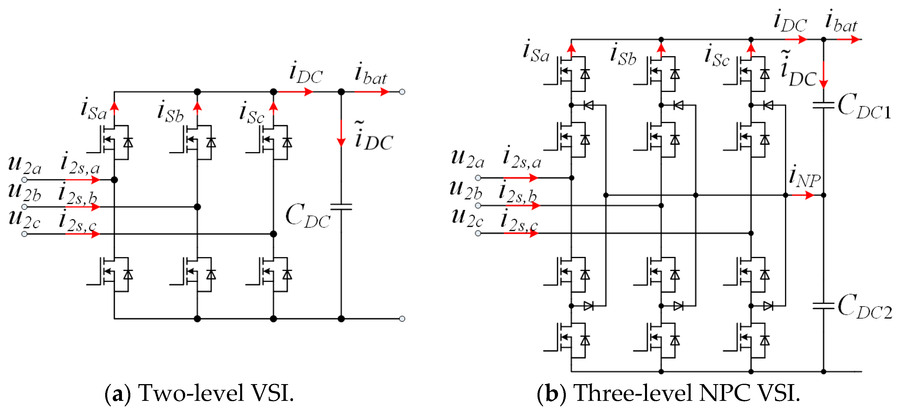
Figure 2 shows the conventional two-level VSI and three-level NPC VSI.
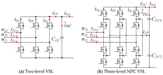
Figure 2.
Voltage source inverters.
3. DC-Link Current Calculation for the Charging Mode
It is obvious from Figure 2 that the DC-link current can be obtained as a sum of the all top switch currents: , , and for the two-level inverter and , , and for the three-level inverter. These currents are the partial line currents (which are the secondary winding transformer currents) , , and , respectively. The top switch currents can be obtained by multiplying the respective line current by the switching function of the respective power switch. It is apparently difficult to operate with these currents as far as they are discontinuous. Therefore, it is reasonable to consider them as continuous functions by excluding the PWM harmonics. Thus, VSI schemes in Figure 2 can be replaced by their averaged models shown in Figure 3.
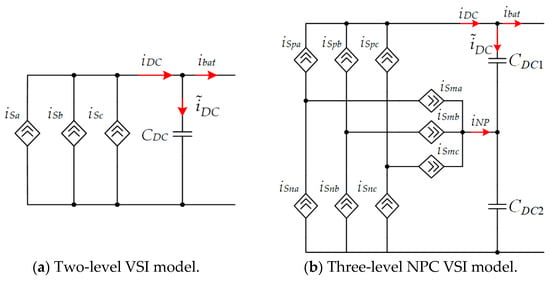
Figure 3.
Averaged models of the inverters.
Consider ESS in charge mode. Assume that the primary winding line currents are sinusoidal as far as VSI operates as an active rectifier.
In this research, switching the functions of the power transistors and the spectral analysis will be used as main mathematical tool. This instrumentation is a powerful technique to obtain any current in any power circuit under periodic processes without the need to write differential equations. This technique can be used for detailed power circuit analysis [28,29,30].
The primary line currents can be written as follows:
The secondary winding currents will be written as follows:
Then, MOSFET currents for the two-level VSI can be obtained by multiplying the secondary winding currents by the switching functions:
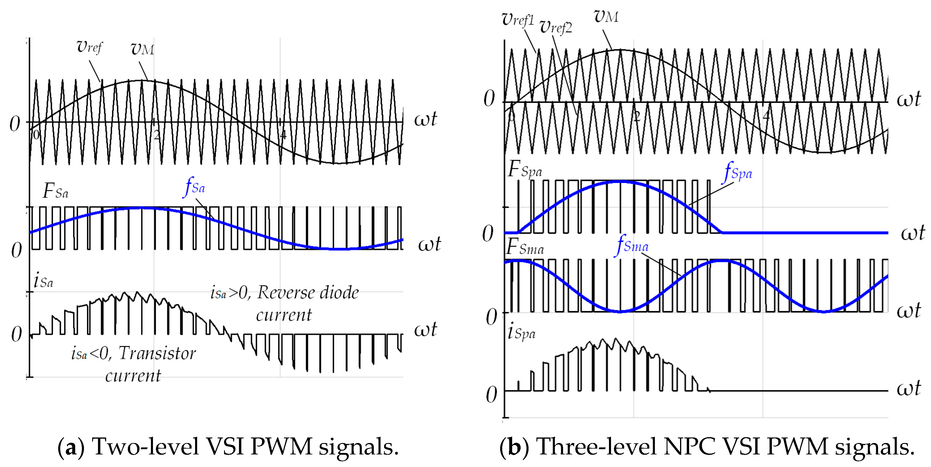
where —switching functions of the respective power switches (MOSFETs). These functions are discontinuous. In order to use continuous functions instead, it is necessary to write the modulation function of the gating signal [28,29,30]. Figure 4 clears up how the pulse width modulation allows us to obtain the modulation function of the gating signal, .

Figure 4.
VSI pulse width modulation and the real power switch current.
It is clear from Figure 4 that the pulse width function of the signal can be found as a limit of FS under infinite PWM frequency : . So, the modulation functions for the power switches for both considered VSI topologies can be found further:
where is the phase angle between the of the grid voltage and the modulation signal; , n is the harmonic order.
Note the equations in system (5) represented as Fourier series of a half of the sine wave in Figure 4b.
Substitution (2) and (4) in (3) gives the result for two-level inverter:
Then, according to the Kirchhoff Currents’ Law and Figure 3:
Equation (7) shows that, in the case of the sinusoidal line currents, the DC-link current in a two-level inverter contains only the DC component. Obviously, in this case, the DC-link capacitor has no voltage ripple. Therefore, its capacitance can be estimated by the generally known formula for the bridge rectifiers with a capacitive filter:
Consider, now, the calculation of in the three-level inverter. Substituting (2) and (5) in (3) gives the result for three-level inverter:
Expressions for the MOSFET currents in the legs B and C are the same as one in (8) with the phase shift by and for phase B and by and for phase C.
After summation of all three currents according to the Kirchhoff Currents’ Law, sine summands generate a positive sequence and, therefore, they result in zero; the second summands result in a constant value of , as in the previous case. The last products form the sum of sine functions:
Several remarks can be made in order to reduce this expression. First, recall that multiplier is zero for all odd harmonics; second, for , all of the summands also form positive and negative sequences and, thus, they are all become zero. So, the rest numbers are for the positive summands and for the negative summands. Thus, this partial DC-link current contains only the triple harmonics. Third, the multiplier diminishes very fast due to squared n in its denominator, i.e., ; ; ; , etc. Therefore, it is quite enough to take into account only the first two values: and . In this case, the partial DC-link current expression can be significantly reduced:
Then, final DC-link current is obtained as follows:
A comparison of Equations (6) and (10) reveals that, in both cases, DC-link currents contain an average value equal to the one defined in (5). The current in the three-level inverter also contains an AC component, represented by triple harmonics defined in (8). The magnitude of this AC component can be found in Equation (8):
This is the magnitude of the AC component, which flows through the capacitor of the DC-link in the three-level inverter when ESS operates in charge mode.
Although the three-level inverter has the significant AC component in the DC-link, it does not affect the rest DC stage behind the DC-link capacitors. This fact is explained by the multilevel inverter operation: the third harmonic in the bottom switch and the bottom DC-link capacitor is the same by magnitude, but is shifted by 180 degrees. This is the reason why two DC-link capacitors have the 150 Hz-ripples separately, but the whole DC-link voltage does not contain third harmonic. Thus, it can be said that the third harmonic of the DC-link current and all other threefold odd harmonics (9, 15, 21, etc.) do not flow further into DC stage, but circulate between the inverter and the DC-link capacitors.
4. DC-Link Current Calculation for the Harmonic Compensation/Offline Mode
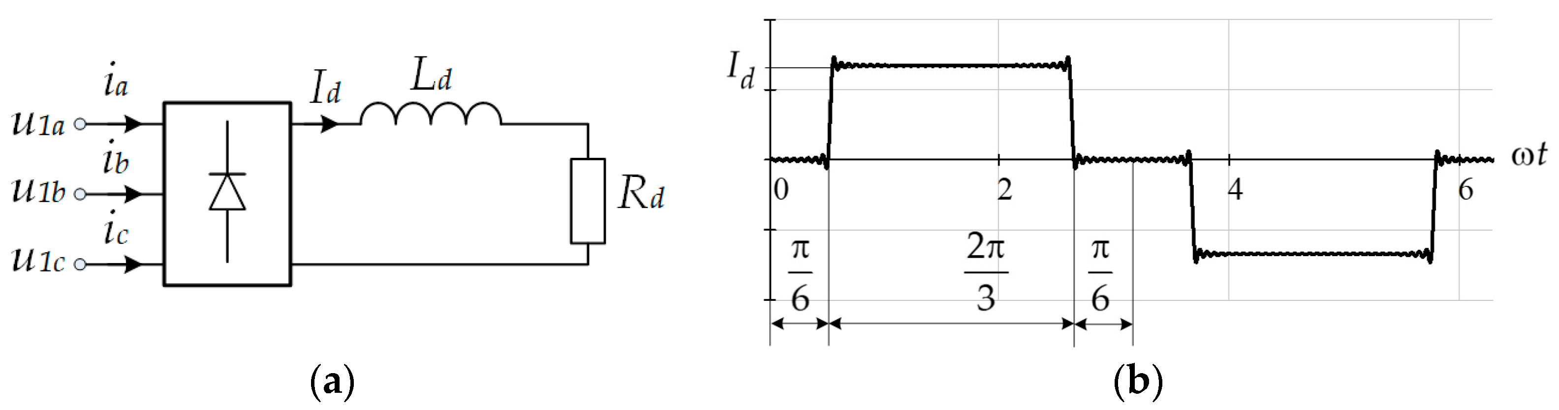
Assume that a diode rectifier, Figure 5a, represents the load and that the waveform in Figure 5b represents its line current.
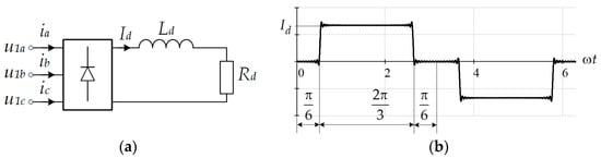
Figure 5.
Diode rectifier as an example of a nonlinear load (a) and its input current waveform (b).
It is known that many loads in three-phase systems are supplied from diode or thyristor rectifiers. Although these rectifiers have different structures, analysis of their input currents shows that, in many cases, such nonlinear loads generate harmonics of the orders , where k is positive integer. This means that the typical harmonic spectrum of a typical nonlinear but symmetrical load contains harmonics with orders 1, 5, 7, 11, 13, etc.
Taking account of the assumption that , the load’s line currents can be represented as periodic current steps with zero intervals (see Figure 5b):
In (11), , where is the average value of the rectifier output current, is the rectifier output power, and is the RMS value of the grid voltage. Let us assign .
Then, the secondary winding currents will be equal to the following:
4.1. Currents in the Two-Level Inverter
The practice shows that, in harmonic compensation mode, the modulation signal in the PWM remains sinusoidal with slight distortions. So, the modulation signals described in (4) can be reused here.
Then, the substitution of (4) and (12) into (3) results in the average components of the top switch currents in the two-level inverter:
Furthermore, to obtain the DC-link current, Equation (6) can be used again. It should be noted that, when summing all three top switch currents, the last term in each current gives the symmetrical negative and positive sequences in sum and, hence, their sum results in zero.
Then, the DC-link current, according to Equation (6):
where terms , , and are defined as follows:
Recall that . The last two multipliers exclude some harmonic components from the current. In particular, equals zero for all even harmonics, i.e., 2, 4, 6, etc. The term equals zero for all triple harmonics, i.e., 3, 6, 9, etc. This means that, in the final current, the only harmonics with numbers 1, 5, 7, 11, 13, … 6k ± 1 (k is a positive integer) remain.
Furthermore, the first seven harmonics with orders 1, 5, 7, 11, 13, 17, and 19 will be calculated using Formula (14) and (15). The results are presented in Table 1.

Table 1.
Harmonic components of current .
The superscripts “p” and “n” were introduced to separate the harmonic components, produced by different harmonics of the line current. For example, the fifth line current harmonic produces the DC-link current’s sixth harmonic with a positive coefficient , while the seventh line current harmonic does the same as the sixth DC-link current’s harmonic, but with a negative coefficient . The numerical values of and can be found from the same technique as described for the charging mode. The only difference is that all calculations have to be made for the fundamental component.
The general form for the resulting current from the calculated harmonics can be rewritten as follows:
4.2. Currents in the Three-Level Inverter
The substitution of (5) and (12) into (3) results in the average components of the top switch currents in the three-level inverter:
The summation of all three currents described in (17) becomes much more complicated than in the previous case due to the products of the Fourier series in the last term of each current. Therefore, it is reasonable to split this action into three steps.
- Summation of the first summands of each current. The first summands taken from each current contain only harmonics with orders 5, 7, 11, 13, etc. These harmonics are generated from the negative and positive sequences and, as far as the load is symmetrical, their sums are zero.
- Summation of the second summands of each current. The second summand represents the multiplication of a Fourier series by the sine function. This is exactly in respect to the previous case with the two-level inverter. So, the partial DC-link current obtained in this step can be written as in (13).
- Summation of the third summands. Consider Fourier series product in the current :
Coefficients in (19) for all three currents are defined in Table 2.
Table 2.
Currents coefficients for definitions (19).
The other two products in the currents and can be represented in the same way:
The summation of all three currents results in the following formula for a three-level inverter:
Analysis of the last sum shows that it takes non-zero values only for the triple-odd harmonics, i.e., 3, 9, 15, etc. This complements the first term, which contains only the triple-even harmonics such as 6, 12, 18, etc.
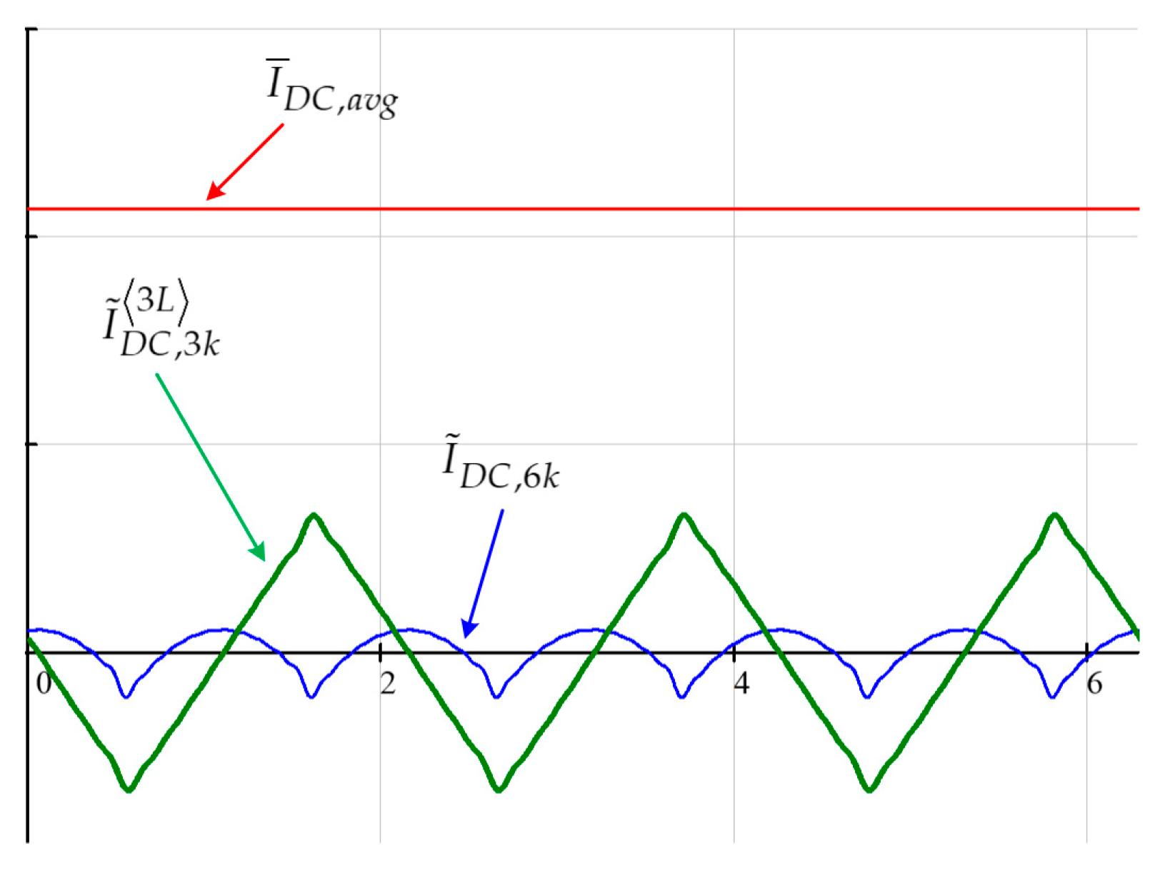
The numerical calculation of the DC-link current in (20) shows that the third harmonic dominates over the rest. Figure 6 shows the waveforms for different current components:
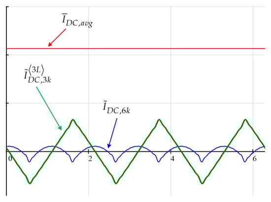
Figure 6.
DC-link current components.
Note that superscript belongs to only one component. This emphasizes the similarity between the DC-link currents of two- and three-level inverters. These currents differ only in one component, .
In an ideal case, the only AC-components of the DC-link current flow to the capacitors. If one tries to obtain the currents in the second DC capacitor, the result is the same AC component , but shifted by 180 degrees. This means that the total DC-link voltage does not contain the triple harmonics. Nevertheless, there is one consideration about three-level inverter and multi-level inverters in general. One estimates the DC-link currents and its AC-component in order to limit the capacitor voltage ripple. For three-level inverters, voltage ripples on each capacitor have one more meaning. It is known that in three-level inverters, multilevel voltage steps are generated from the DC-link capacitor voltages. In fact, the quality of the generated voltage depends on the DC-link voltage balance. However, there is always a non-zero probability of the DC-link voltage unbalance, and this is a well-studied problem in the literature [31,32]. The unbalance can be static (when the average values of the capacitor voltages are different) and dynamic (which is caused by the voltage ripples). It is not so difficult to deal with the static unbalance as with the dynamic. In our analysis, the DC-link current component is the main source of the dynamic unbalance and it influences the quality of the input line current.
4.3. Limitation of the Harmonics Number
An interesting question is how many harmonics should be taken into consideration in (14) and (20) to estimate the DC-link capacitor current more precisely. Returning to Figure 1, one can see that the input stage of the ESS includes transformer and the LC filter. This combination in an equivalent circuit can be represented as an LCL stage where the first “L” denotes the input transformers’ leakage inductances. So, the input stage of the ESS has an AC response as one, depicted in Figure 7.
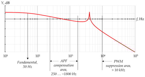
Figure 7.
Input stage AC response.
In Figure 7, is the LCL stage transconductance in logarithmic scale [33,34]:
where is the input line current and is the voltage generated by the ESS’s voltage source inverter.
There are three areas to be highlighted. The first is the fundamental frequency area (50–60 Hz). The second is the APF compensation area—a bandwidth from 250 Hz to about 2 kHz (20 dB/decade), where the higher harmonics of the nonlinear load are located and the PWM suppression area (40 dB/decade). The power quality standard EN 510160 determines requirements for the harmonics in the power supply voltage up to 25th harmonic (1250 Hz), while IEEE 519-2022 standard does up to 50th harmonic (2500 Hz) [35,36]. So, the high side of the APF bandwidth is defined by the particular system technical requirements and the applied standard.
As can be seen from Figure 7, the higher harmonic order, the lower the transconductance of the input stage of the ESS. This means that the higher order of the harmonic one obtains using (13), the higher will be the calculation error, because the previously described calculation method does not take into account the AC response of the input stage. It can be concluded that, for the DC-link current, it is quite enough to obtain harmonics with orders up to 13.
It is clear that the sixth harmonic component has the dominating contribution in the DC-link current in the two-level inverter. Suppose that the DC-component flows through the DC-link and all the AC components flow through the DC-link capacitor. The capacitor current ripples can be easily found from (14) using only the dominant harmonic component:
Summation of two cosine terms results in a new cosine function with the swing (double magnitude):
For an active power filter, the capacitor voltage ripples are estimated as follows:
where is the equivalent series resistance of the capacitor that is a datasheet parameter. Formula (23) can be used to estimate the required capacitance taking account of the harmonics of the load.
Capacitor instantaneous voltage can also be obtained from Equation (19) (in this way ESR is considered to be negligible):
For the three-level inverter, it is needed to estimate the value of the third harmonic to estimate the dynamic unbalance. The total voltage ripple across the DC-link can be obtained using (24), but the capacitance of each capacitor must be doubled due to their series connection in three-level inverter. It should be noted that the third harmonic components do not flow further into the DC stage to the battery as far as they are circulating between the inverter and the DC-link capacitors.
4.4. Influence of a DC Stage Impedance
For an energy storage system, the battery impedance has to be taken into account. Figure 8 shows the model of the DC stage of the ESS for only AC components. To model a Li-ion battery, an equivalent circuit and its parameters from [37] are used, but the controlled DC source is omitted due to the model being applicable only for the AC components.
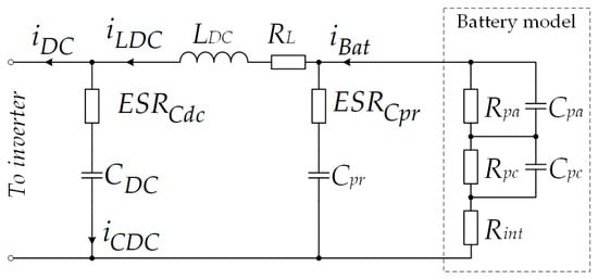
Figure 8.
DC-stage of ESS with the Li-Ion battery model for AC components.
Figure 8.
DC-stage of ESS with the Li-Ion battery model for AC components.
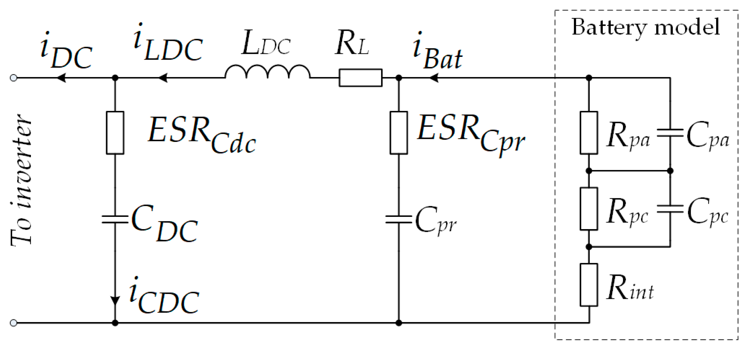
The designations in Figure 8 are the following:
- —Inductance for limitation of the AC current component;
- —Ohmic resistance of the inductive filter;
- —Protective capacitor (about 10–50 μF) and , its equivalent series resistance. Protective capacitor closes the inductor current loop if switches in the pre-charge circuit break when the current flows through the inductor.
Battery model parameters are the following: are the resistance and capacitance of the activation polarization, respectively; are the resistance and capacitance of the concentration polarization, respectively; and is the internal ohmic battery resistance [37].
The task here is to find out how the AC current components are shared between the capacitor () and the rest of the circuit ().
Before proceed, it should be noted that the capacitances and typically take the values of farads or even kilofarads and their impedances for the considered AC component with frequency 6 ω lie in the microohms range. So, to reduce the circuit complexity they can be omitted.
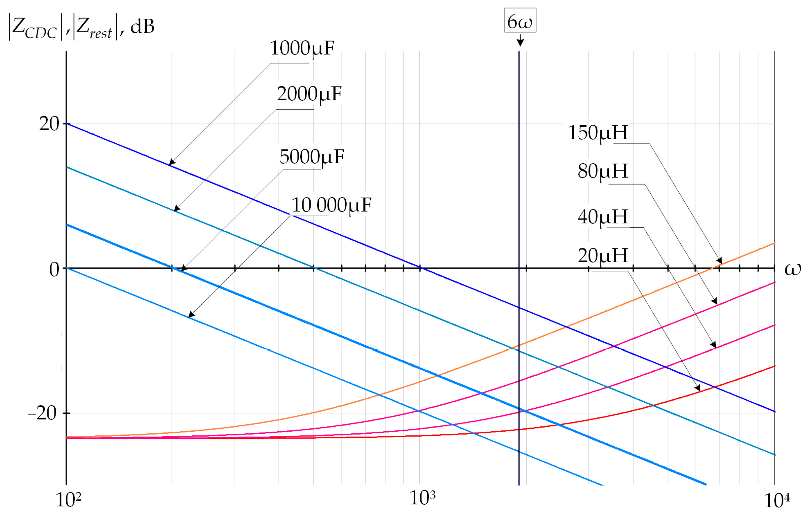
It becomes obvious that the main parameters defining the relation between the currents and are the capacitance and the inductance . The currents are defined by the DC-link impedance:
and the impedance of the rest circuit:
Figure 9 shows the impedances expressed in (25) and (26) for different values of and .
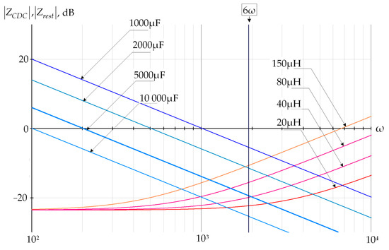
Figure 9.
Relation between impedances and .
Assume the AC-component of the DC-link current is known and the task is to find the optimal relation between the mentioned passive components of the DC-link. The current ripples are to be find using simple equations:
It is clear that the DC voltage ripples can now be obtained from (27) as follows:
Formula (25) can also be used for an active power filters applying .
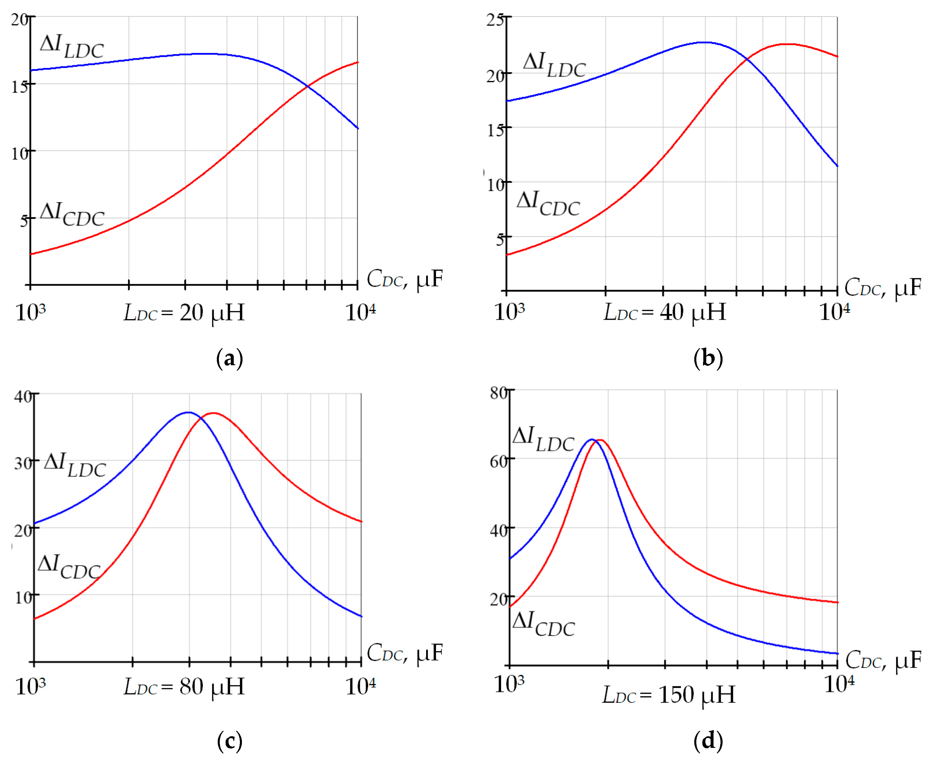
Figure 10 shows an example of the AC current component distribution between the DC-link capacitor and the rest of the DC-link stage for different values of and . This example is given for a numerical value of .

Figure 10.
Current distribution within the DC stage for different parameters of and : (a), (b), (c), (d).
It is seen from Figure 10 that, for some values of and , resonance occurs at frequency . To prevent an undesirable overcurrent due to resonances, it is reasonable to set the inductance first and then choose DC-link capacitance more to the right from the resonance point. For example, if , then must be more than 4000 μF, see Figure 10c, while for , has to be more than 2000 μF, Figure 10d. It is also recommended that current should be less than to make the most part of the current ripples flow through the DC-link capacitor, but not to flow to the battery.
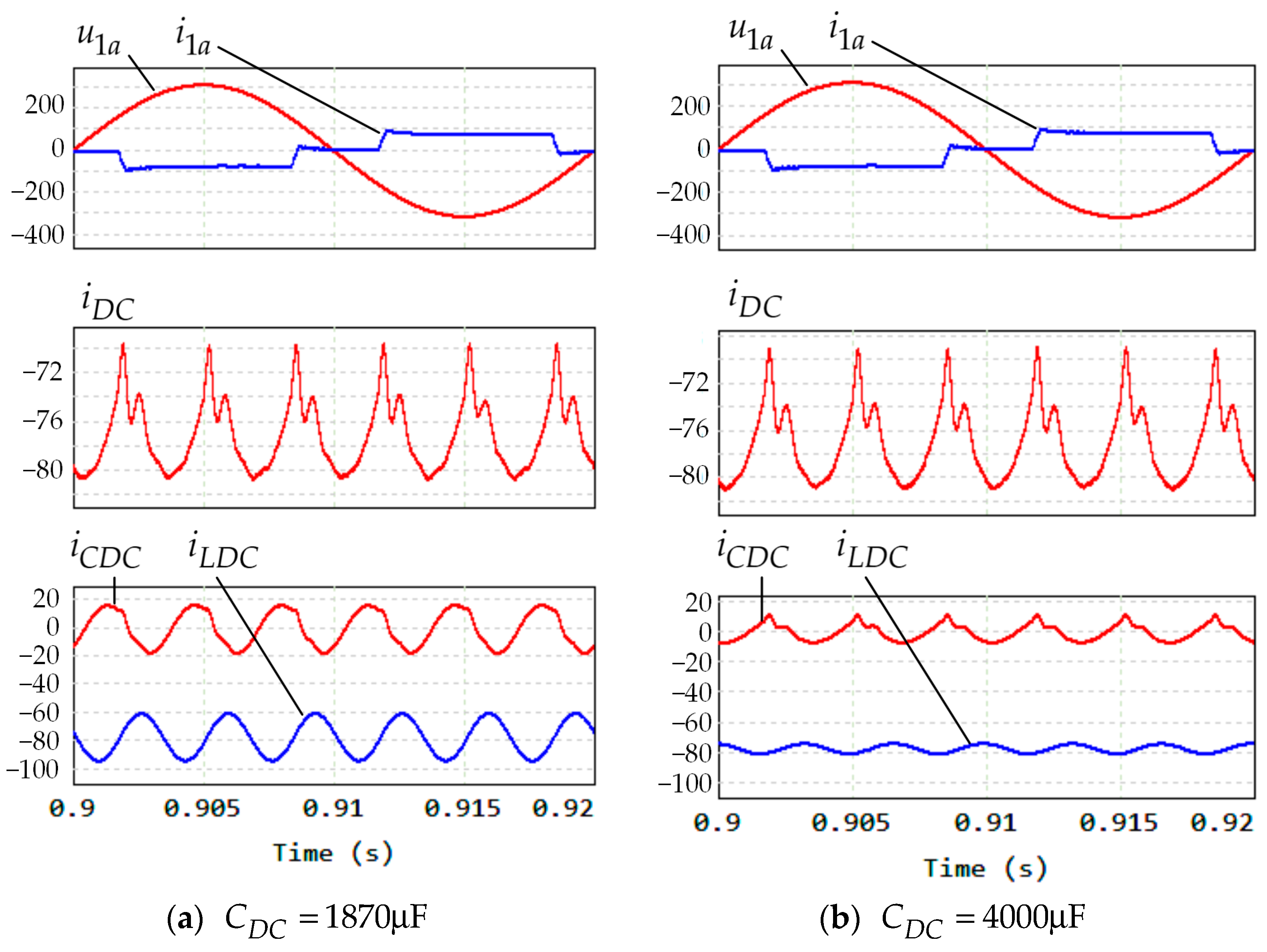
The following example clearly demonstrates negative consequences when the DC-link capacitance was set and the resonance occurred. Assume that and . The DC-link current has the sixth harmonic with magnitude 3.85 A. Then, from (24), it can be found that and , while for and . Figure 11 from the simulation model confirms these results.
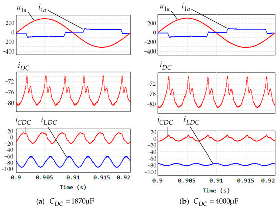
Figure 11.
Simulation results for LDC = 150 μH.
5. Simulation Results
In order to verify the theoretical results, simulation models in PSIM were used. The model’s parameters are listed in Table 3.
Table 3.
Simulation model parameters.
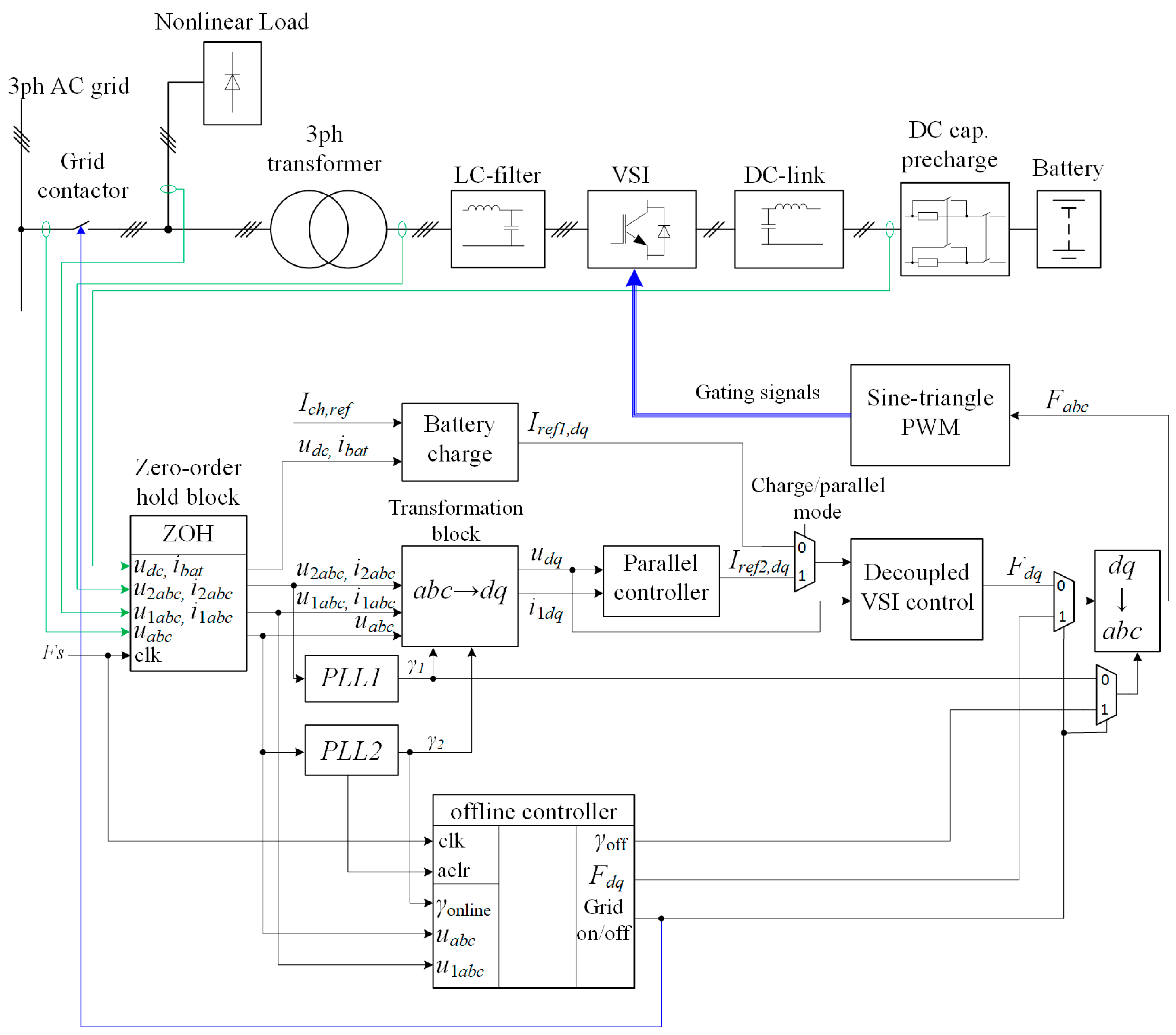
The model’s scheme is presented in Figure 12. The grid contactor provides correct operation when the grid is off.
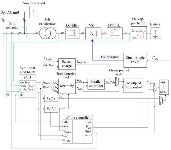
Figure 12.
ESS simulation model scheme. Blue arrows denote the control signals outgoing from the control system, green arrows denote sensor signals ingoing to the control system.
The control system contains the following key modules:
- Zero-order hold block samples the input signals and holds them until the next clock cycle signal with the frequency Fs = fpwm = 20 kHz. This module emulates the operation of the analog-to-digital conversion in a digital control system.
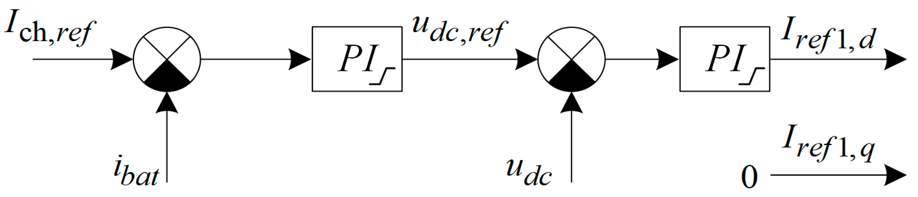
- Battery charge block contains two feedback loops for the charge mode operation. The inner loop is the battery voltage loop and the outer one is the battery charging current loop, Figure 13. This module implements the CC-CV charging strategy: at first, the battery is charging with the constant current and its voltage is increasing; as the voltage reaches the defined value, it remains constant until the battery is fully charged. The output signal is the VSI reference current signal Iref1,dq.
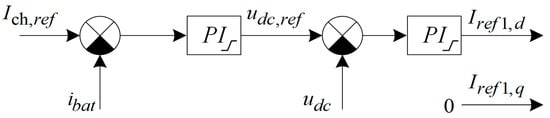 Figure 13. Battery charging control loops.
 - The direct and the inverse Park transformation blocks abc→dq and dq→abc implement the transformation of the voltage and currents from the abc frame to the rotating reference frame dq0 (in our model zero-sequence component is not presented).
- Phase-locked loops PLL1 and PLL2 are used to synchronize the ESS with the grid voltage. The first one (PLL1) provides synchronization using the transformer’s secondary voltage, while the second one (PLL2) provides the synchronization using the grid voltage behind the main grid contactor. This double synchronization is needed to make the transients softer during the grid contactor commutations. The first one generates signal γ1 from the external grid voltage, while the second forms signal γ2 from the transformer secondary winding voltages. When operating in the offline mode (grid voltage is off), γ1 = 0, γ2 represents the triangular waveform and is used for the control synchronization. When the grid voltage restores, signals γ1 and γ2 are obviously not synchronized and the grid contactor is still open. It is clear that closing the contactor may lead to unpredictable transients in the point of common coupling, such as overcurrents, and can cause system failure. Normally, the system has to wait until γ1 and γ2 to go synchronously or with sufficiently small differences. After that, the offline controller triggers the grid contactor and connects the system to the main grid with a sufficiently soft transient.
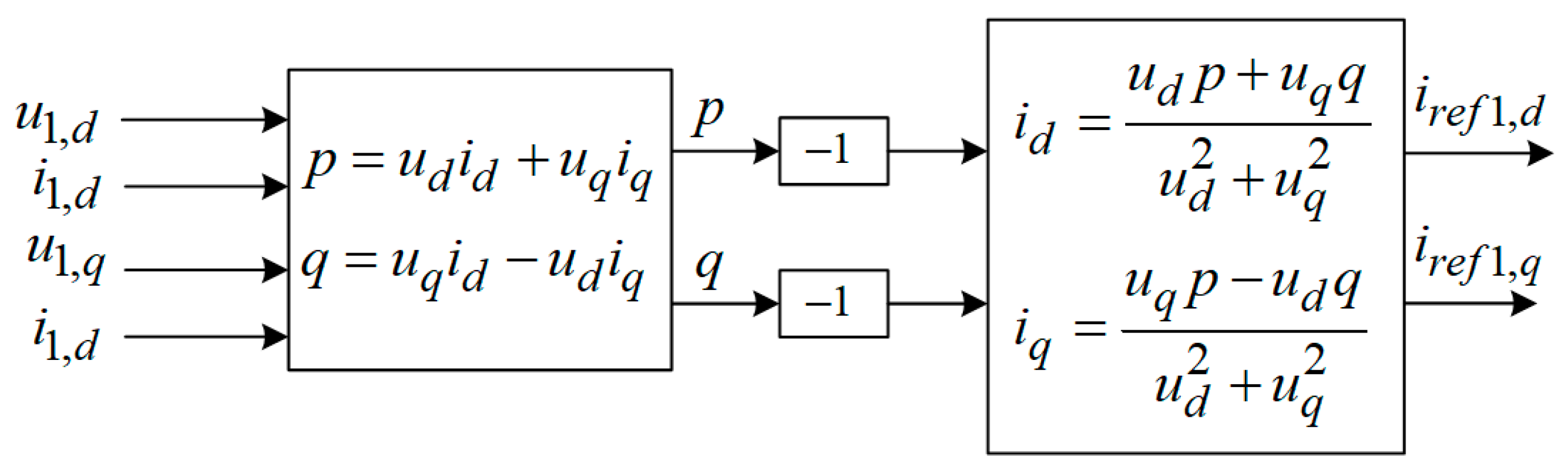
- Parallel controller block represents the main algorithm of ESS: The block takes the grid voltages and the load currents in the dq frame, calculates the instantaneous powers p and q according to the instantaneous power theory, reverses their signs, and converts them back into the dq frame as the reference signals for the ESS line currents, Figure 14. The band-stop filters were added to prevent undesirable resonances in the ESS input stage.
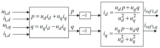 Figure 14. Parallel controller based on the instantaneous pq-theory.
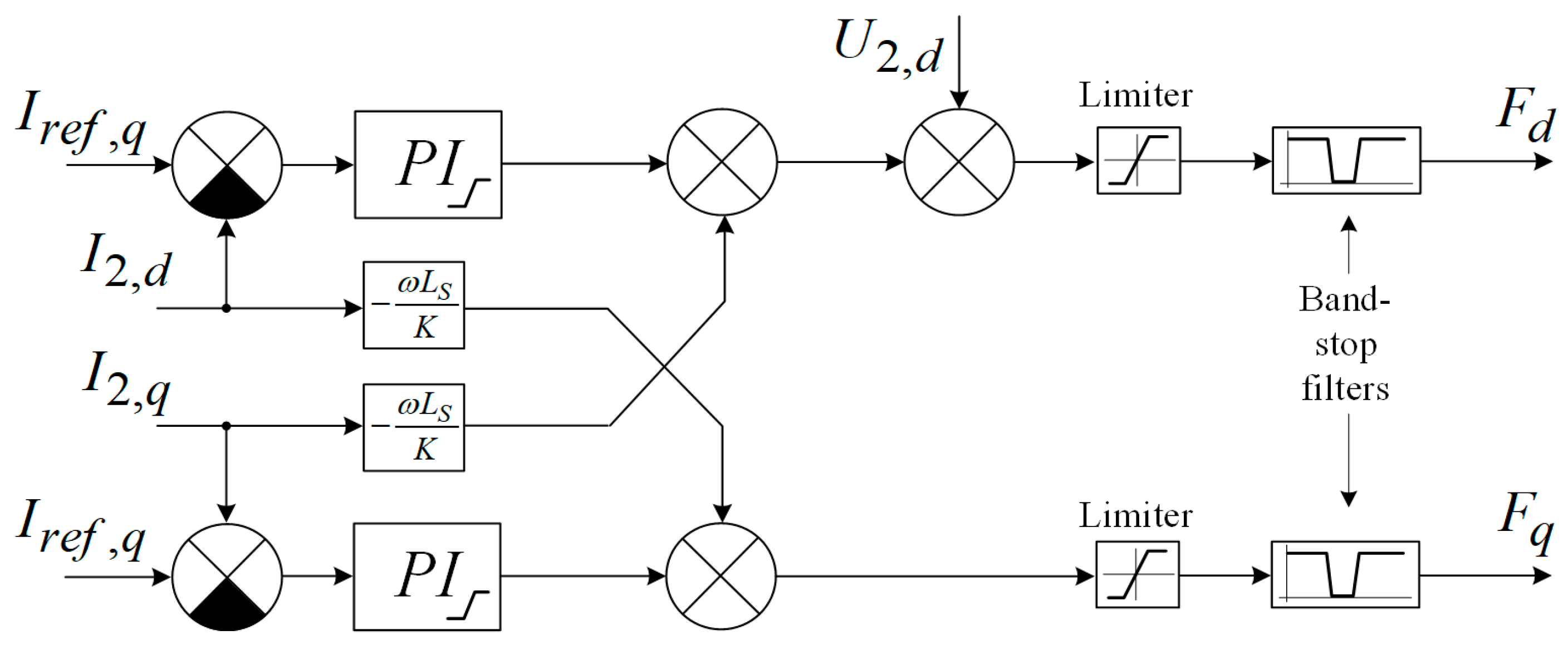
 - Decoupled VSI control (Figure 15) block takes the inverter line currents as the reference signals in the dq0 frame. There are two independent (decoupled) inverter current feedback loops in this block. The output signals Fdq represent the reference signals in the dq0 frame. The inverse Park transformation converts them into the abc frame.
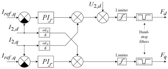 Figure 15. Decoupled control of the ESS inverter.
5.1. Simulation of Rectifier Mode: Battery Charging
In this mode, ESS operates as an active rectifier with the load current . The battery internal resistance and the charging current define the charging voltage. To simulate the behavior of the Li-ion battery, the model described in [37] is used with the parameters listed in Table 3. The initial state of charge (SoC) is set to 75%. Battery voltage is 530 V. Charging voltage is .
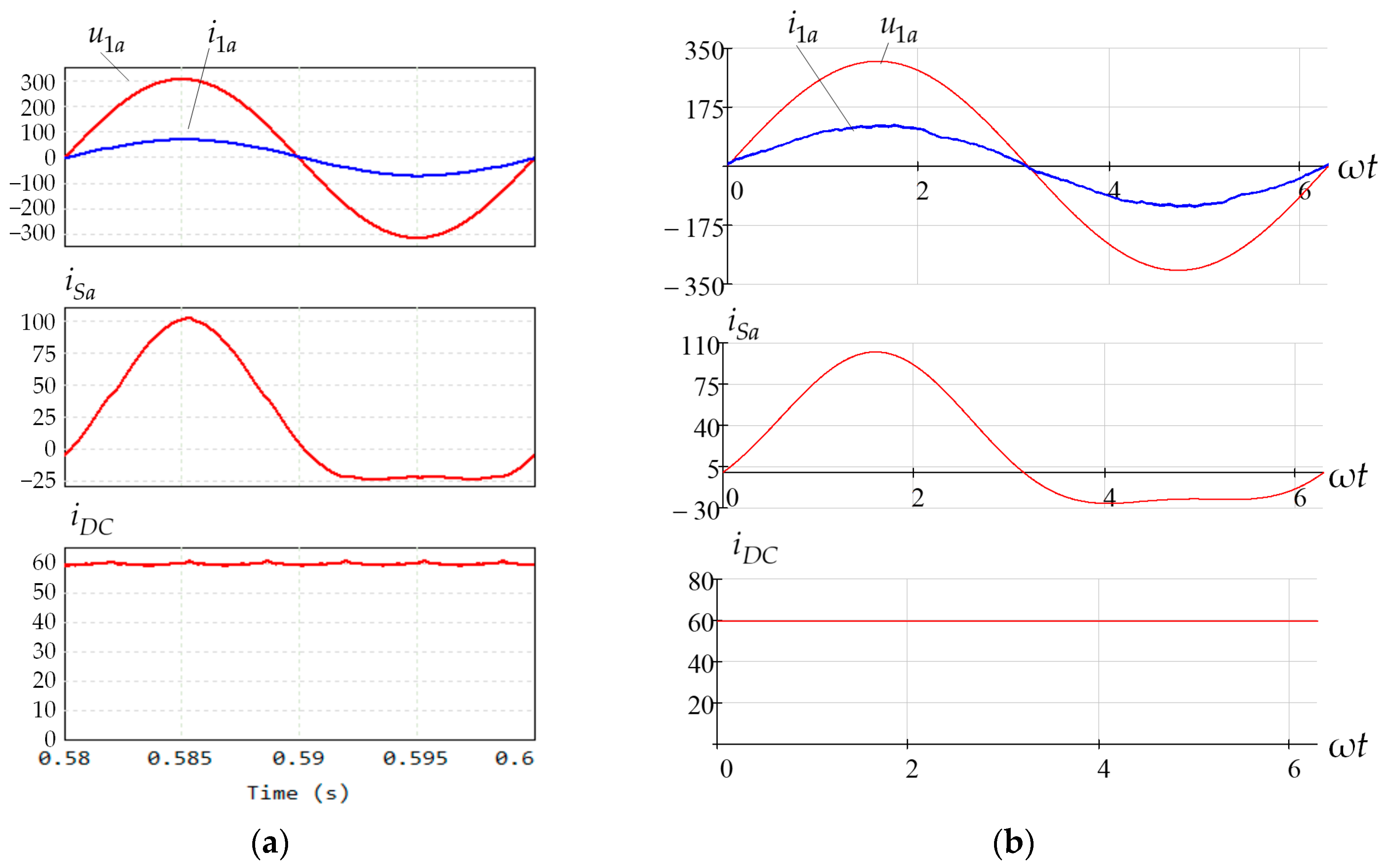
Figure 16a shows the simulated waveforms and Figure 16b shows the waveforms obtained from Equations (1)–(3), (5), and (6). The average DC-link current value, measured in PSIM, equals to 60 A; the DC charging voltage is 540 V, and the RMS value of the transformer secondary current .
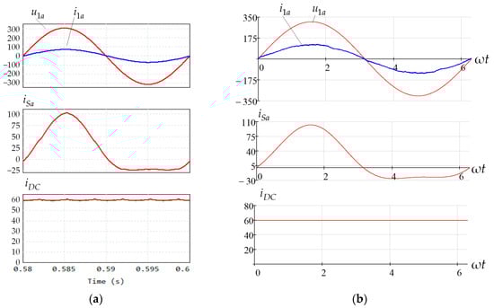
Figure 16.
Waveforms of the charge mode with two-level inverter: (a) simulation in PSIM; (b) waveforms obtained in Mathcad.
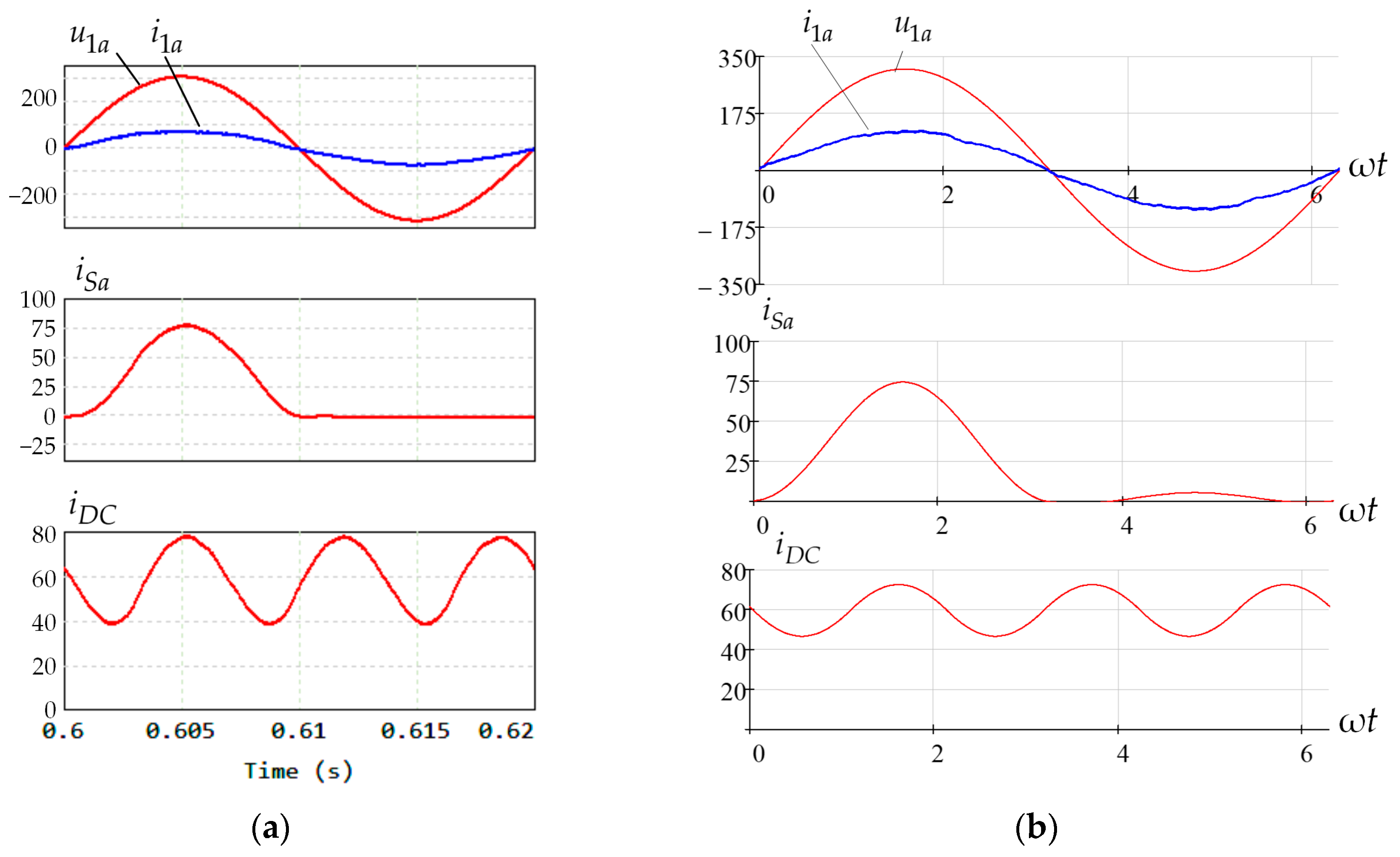
Figure 17 shows the same waveforms for ESS with a three-level inverter.
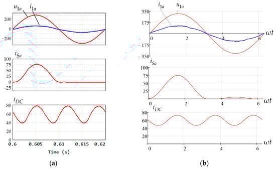
Figure 17.
Waveforms of the charge mode with the three-level inverter: (a) simulation in PSIM; (b) waveforms obtained in Mathcad.
It should be noted that the simulated waveform of the power switch current for the inverter leg in phase “A” shows only the average component that is measured with a second-order low-pass filter. The real current contains the PWM component as well. Figure 16 proves the conclusions made for Equation (6), being that, for the sinusoidal input current, the DC-link current contains only the PWM component and the DC component.
For the three-level inverter in ESS and battery charge mode, it is seen that the DC-link current contains a triple harmonic. This AC current component flows through the top DC-link capacitor. The same harmonic component, shifted by 180 degrees, flows through the bottom DC-link capacitor. The simulated waveforms reveal the correctness of the mathematical results.
5.2. Simulation of the Nonlinear Load Supply Mode
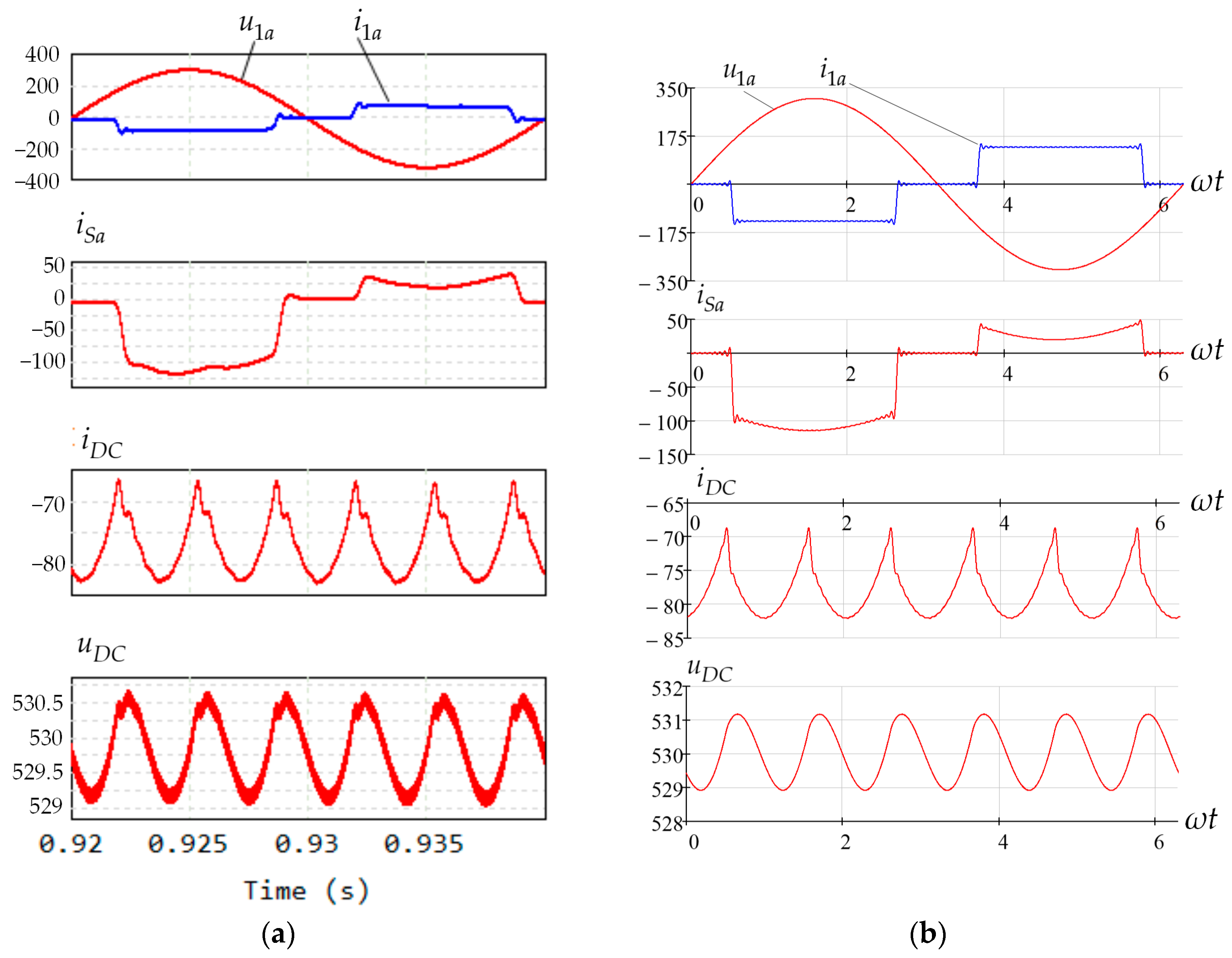
Figure 18 shows the simulated and calculated results for the AC voltage and current (), switch current () and DC-link current (), and voltage () for ESS based on a two-level inverter.
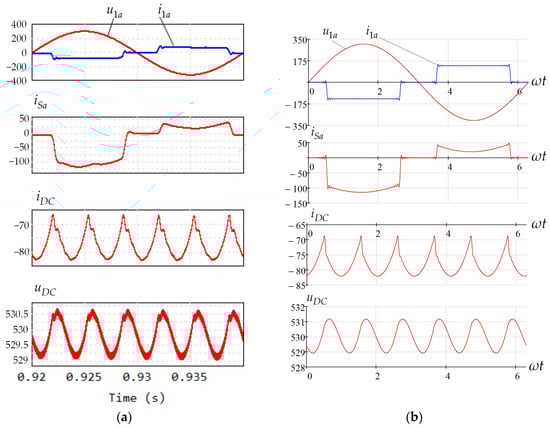
Figure 18.
Waveforms of the nonlinear load supply mode: (a) simulation in PSIM; (b) waveforms built in Mathcad.
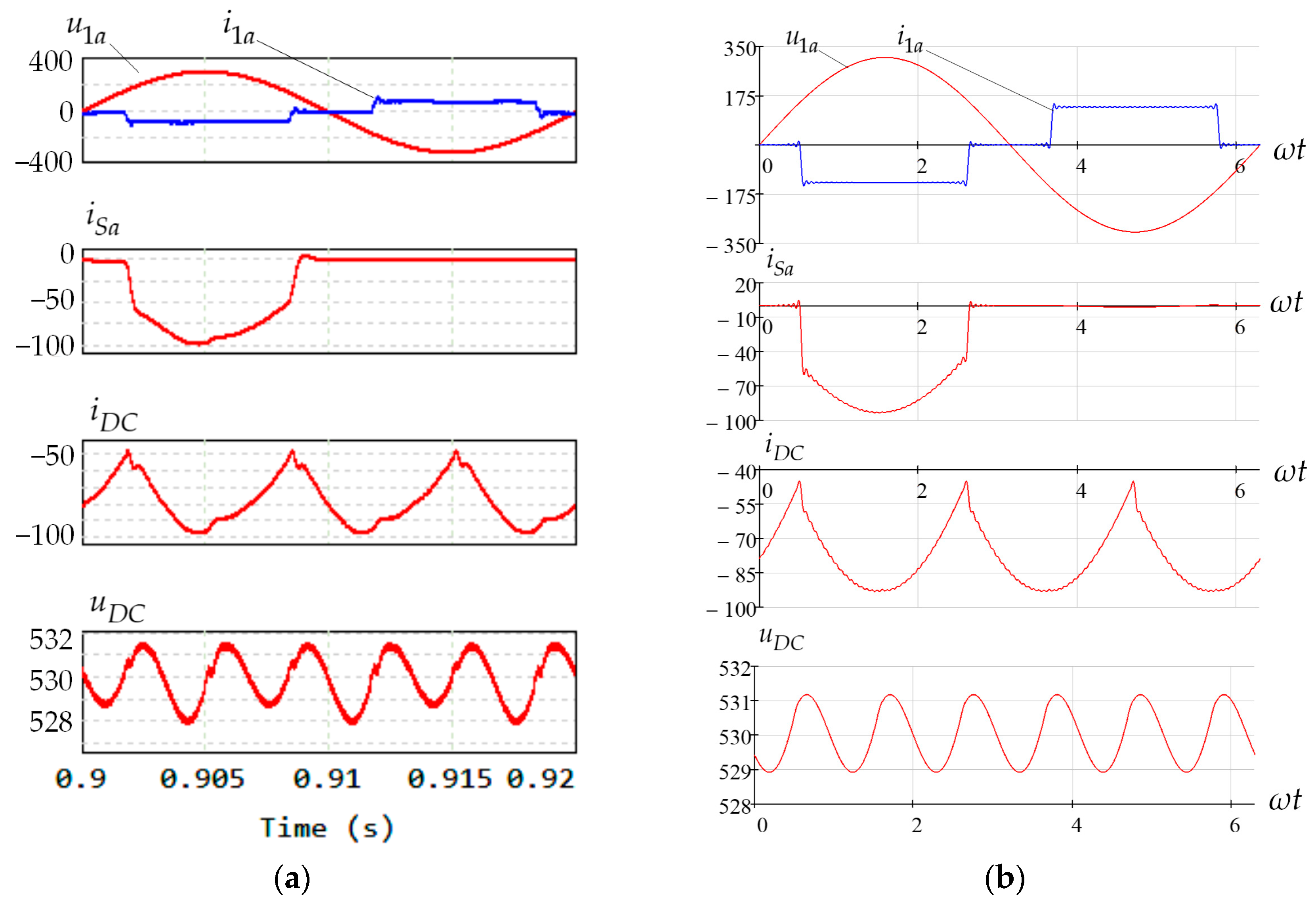
Figure 19 shows the same waveforms for ESS based on the three-level inverter. The simulation confirms that both topologies demonstrate very similar operations considering the processes in the DC-link stage. The difference is the only third harmonic in the DC-link of three-level inverter. However, the third harmonic does not affect the circuit behind the DC-link capacitors because it circulates between the DC-link capacitors and the inverter.
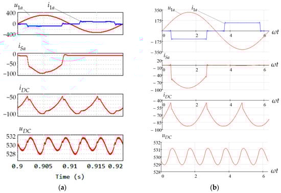
Figure 19.
Waveforms of the nonlinear load supply mode with ESS based on the three-level inverter: (a) simulation in PSIM; (b) waveforms built in Mathcad.
For the two-level inverter waveforms of the switch, the current represents a current flowing through a power transistor (MOSFET or IGBT) with an antiparallel diode. When ESS operates in charge mode, the inverter operates as an active rectifier. If the switch current flows through a transistor, it is negative, and when it flows through its antiparallel diode, it is positive.
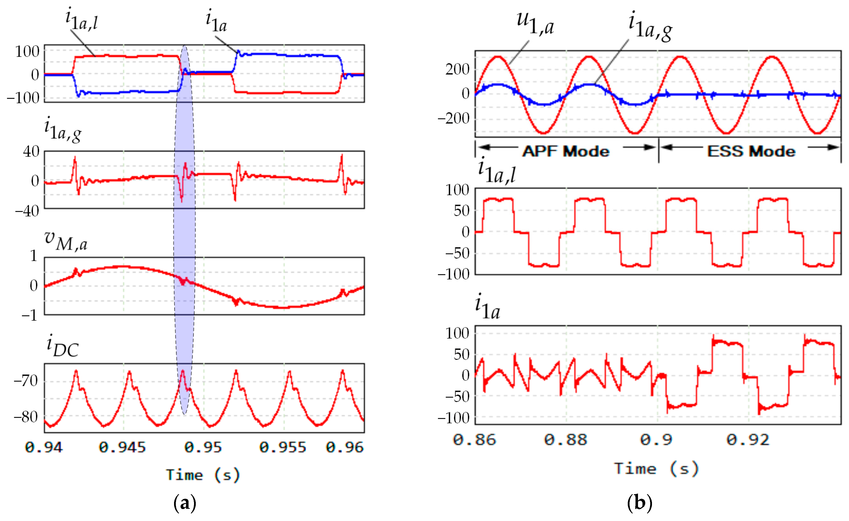
One noticeable difference is small single notches in the DC-link current when ESS supplies the diode rectifier. These notches appear due to the limited bandwidth of the system. Such effects are considered in detail in [38]. Briefly, the control system of ESS is based on the pq-theory and uses instantaneous values. Figure 18, Figure 19, Figure 20 and Figure 21 show that the load current is discontinuous: it consists of the zero-current pauses and approximately square pulses. When the control system detects step of the load current, it tries to generate respective reaction and forms the control signals. The control reaction affects the modulating signal and, as a consequence, ripples and notches in the current consumed from the DC-link. The explained processes are represented in simulation waveforms in Figure 21.
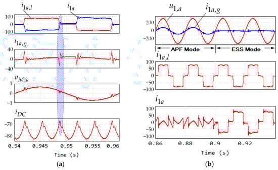
Figure 20.
Waveforms explaining the appearance of the notches in the DC-link current and their influence on the grid current (the shadow highlights the notches in the grid current, modulating signal and their influence on the Dc-link current) (a) and operation in the APF and ESS modes (b).
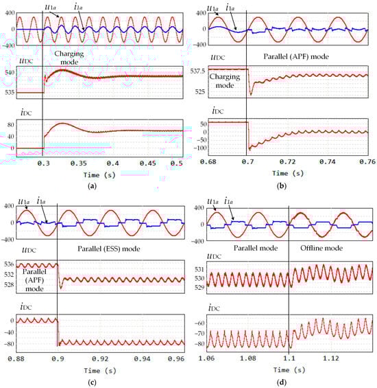
Figure 21.
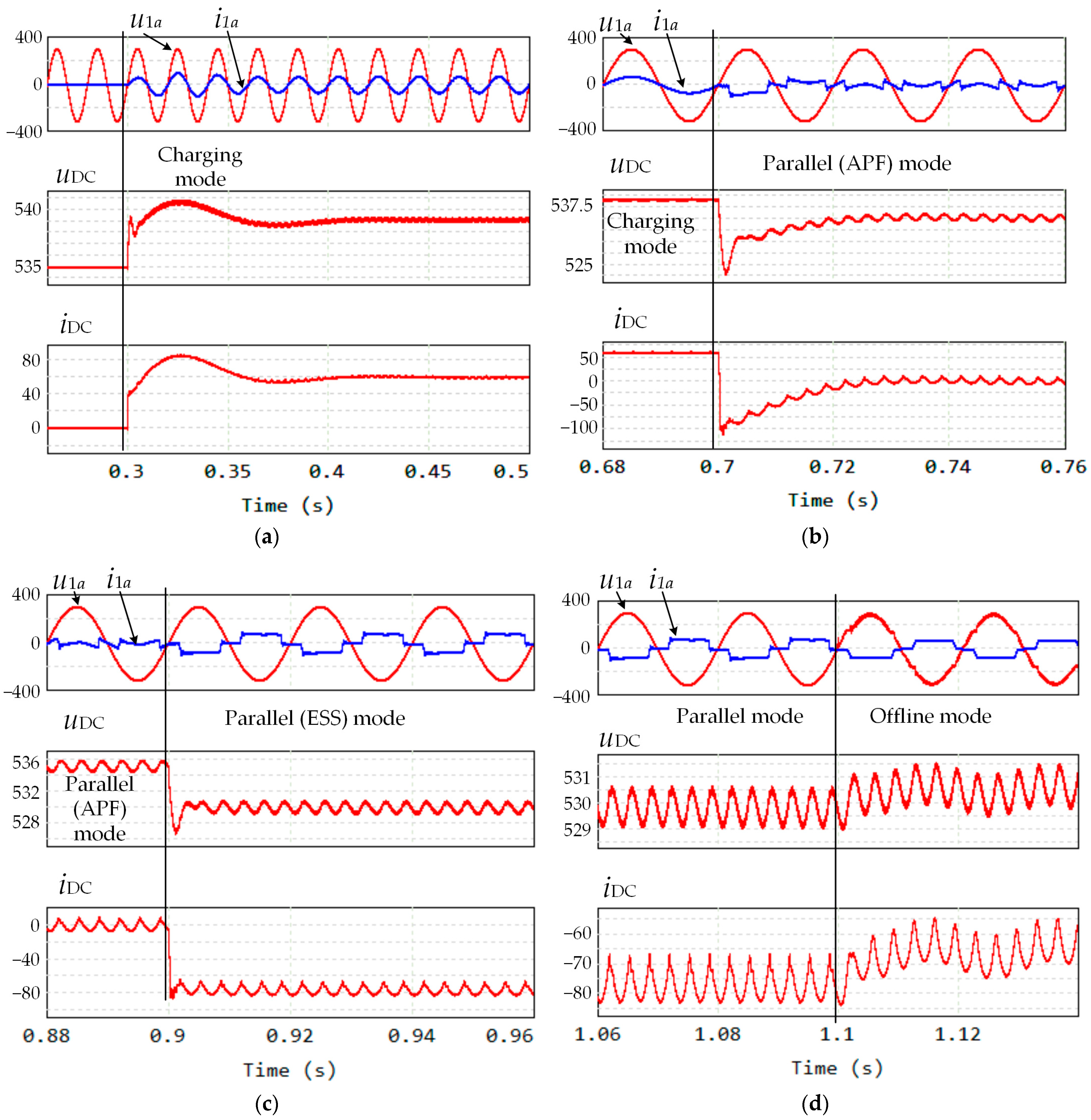
ESS input current, DC-link voltage, and current in transients: transient from idle to charging mode (a); transient from charging node to APF mode (b); transient from APF mode to ESS mode (c); transient from during the grid disconnection (d).
The designations in Figure 20, a are the following: is the load current; is the current, generated by ESS to supply the load; is the current consumed from the grid; and is the modulating signal.
This current reveals the error between the load current and ESS-generated current. This error may be more-or-less dependent on many factors, but it still presents in the system. Figure 20, a shows that when ESS tries to reproduce the slope of the load current, this leads to a respective leap in the modulation signal and, as a consequence, a sudden change in the current consumed from the DC-link.
This phenomenon directly may influence on the grid current harmonic content. Figure 20b shows the operation of ESS in harmonic compensation mode (APF mode) and load power compensation mode (ESS mode). Total harmonic distortion of the load current is 30.8%, and in APF mode the THD of the grid current is 11.6%.
5.3. Simulation Results for DC-Link During the Transients
Figure 21 shows the waveforms for the ESS voltage and currents when it switches between different modes. The first one in Figure 21a shows the transient from standby mode to the charging mode. The second set of waveforms (Figure 21b) represents the transient from the standby mode to the parallel operation. The difference between these is clear. In the charging mode, ESS operates as an active rectifier and consumes pure sine current from the grid. As expected, in this mode DC-link, the current does not contain any AC-component. On the contrary, while operating in the parallel mode (Figure 21c,d), six-fold ripples can be seen in the DC-current and voltage. One can see that the first parallel mode, when the ESS generates only non-active power components, there is no DC-component in the DC-link current, as there is no active power transmission to the load. When the system switches to the parallel (ESS) mode, the active component is added and the respective DC-component appears in the DC-link current. Similar waveforms are presented in Figure 21d, when ESS switches to the offline mode. The transients in the DC-link voltage and current are acceptably soft.
6. Summary
Summarizing the results, we conclude that the presented method to analyze the DC-link currents allows for a simple way to analyze current distribution in the DC-link. The main features of the presented method are as follows:
- Universality. This feature originates from the switching functions method and spectral analysis. These calculation techniques allow us to obtain any current or voltage in any power circuit operating under periodic voltages. Calculating the DC-link currents provided DC-link analysis in this research.
- Complex DC-stage accounting. Known DC capacitor estimation techniques are limited with this opportunity. In the considered case DC-stage, behind the capacitors is the current-limiting inductor, protective capacitor, and battery. All of these components need to be taken into consideration to obtain the proper current distribution and to estimate the DC-link capacitors properly.
- The presented method also allows us to estimate how the load nonsymmetry would influence the DC-link currents, because they are calculated directly from the line currents. Furthermore, we can now predict the harmonics of the DC-link currents if we know the harmonics of the load current.
- Usage of the switching functions and spectral analysis does not require complicated mathematical derivations such as differential equations, integrations, etc. Even Fourier series can be written much easier using the Fast Fourier Transform available in known math software such as Mathcad, Maple, etc. Note that, compared to simulations in specific software such as PSIM v2022.2 or Matlab Simulink v2021b, a system like one in this research takes 1–2 h, while the calculation of one fundamental period in a steady state takes less than 1 min.
7. Conclusions
In this research, we reveal that usage of the switching functions and spectral analysis provides effortless calculation of the currents and voltages in a power circuit of different inverter structures. This approach allowed us to obtain the origin of the DC-link current harmonics in two-level and three-level NPC inverters. What is more, while calculating the DC-link currents, we took into account the operating conditions of the inverter, such as active rectifier mode (during battery charging) and harmonic generation mode (APF operation). There are two key points to be highlighted.
The first point is that the roughest operating conditions are in the harmonic compensation mode; it is shown that the two-level inverter has six-fold harmonics, which are the inverse-proportional to their orders, and the three-level inverter has the same harmonics plus three-fold ones, which are inversely proportional of their orders. It important to note that the DC-link currents in both inverter topologies have the same harmonic content. However, the DC-link capacitor current in the two-level inverter contains only six-fold harmonics, while the DC-link capacitors in the three-level inverter also contain triple harmonics as well. Triple harmonics in the DC-link capacitors of the three-level inverter are opposite in phase and do not produce voltage ripples across the whole DC-link, but, nevertheless, affect the voltage steps at the AC side. Therefore, this phenomenon, known as dynamic unbalance, needs to be taken into account during system design based on this NPC converter.
The second point is that our method to define the DC-link capacitor current takes into consideration the rest of the DC-stage in a battery energy storage system, including battery impedance. In other words, we show how the parameters of the DC-stage (filter inductance, DC-link capacitance) affect the distribution of the harmonics between the DC-link capacitors and the rest components (inductance, protection capacitor, battery). This information allows for an engineer to choose DC-link capacitance not only to keep the voltage ripples at the predefined rang, but also to limit the AC component of the current flowing through the battery.
The simulation of the power system revealed a difference between the mathematical model and the simulation model. The small notches that appeared in the grid current and the DC-link current originate from the limited bandwidth of the system. This phenomenon, however, does not affect the main conclusions made for the DC-link capacitor currents.
Summarizing all of the results, we can conclude that the presented DC-analysis technique allows us to estimate the optimal DC-link parameters to limit the voltage ripples and AC current component flowing through the battery. Further research will be conducted on the experimental validation of the obtained results and the adaptation of the presented calculation technique to other types of converters.
Author Contributions
Conceptualization, M.D.; methodology, M.D. and S.B.; software, M.D.; validation, M.D. and A.U.; formal analysis, S.B.; investigation, S.B. and M.D.; resources, M.D. and S.B.; data curation, A.U.; writing—original draft preparation, S.B.; writing—review and editing, A.U. and S.B.; visualization, M.D.; supervision, S.B.; project administration, S.B.; funding acquisition, A.U. All authors have read and agreed to the published version of the manuscript.
Funding
The work was carried out with the support of the Russian Science Foundation № 23-29-10055, https://rscf.ru/project/23-29-10055/ (accessed on 16 December 2024), with the support of Government of Novosibirsk Region, agreement № r-67.
Data Availability Statement
The data presented in this study are available on request from the corresponding author. The data are not publicly available due to privacy issues.
Conflicts of Interest
The authors declare no conflicts of interest.
References
- Khan, S.; Singh, B.; Makhija, P. A review on power quality problems and its improvement techniques. In Proceedings of the Conference on Innovations in Power and Advanced Computing Technologies (i-PACT), Vellore, India, 21–22 April 2017; pp. 1–7. [Google Scholar] [CrossRef]
- Bhattacharyya, S. Power Quality Requirements and Responsibilities at the Point of Connection. Ph.D. Thesis, Technische Universiteit Eindhoven, Eindhoven, The Netherlands, 2011. (Research TU/e/Graduation TU/e), Electrical Engineering. [Google Scholar] [CrossRef]
- Dehury, D.; Mishra, R.N.; Panda, R. Power Quality Enhancement by Shunt Active Power Filter Employing Different Control Strategies: A Concise Review. In Proceedings of the 1st International Conference on Circuits, Power and Intelligent Systems (CCPIS), Bhubaneswar, India, 1–3 September 2023. [Google Scholar] [CrossRef]
- Zhang, J.H. An analysis of shunt active power filter based on instantaneous reactive power theory. In Proceedings of the 7th International Power Electronics and Motion Control Conference, Harbin, China, 2–5 June 2012. [Google Scholar] [CrossRef]
- Okeke, T.U.; Zaher, R.G. Flexible AC Transmission Systems (FACTS). In Proceedings of the International Conference on New Concepts in Smart Cities: Fostering Public and Private Alliances (SmartMILE), Gijon, Spain, 11–13 December 2013; pp. 1–4. [Google Scholar] [CrossRef]
- Peng, F.Z.; Flexible, A.C. Transmission Systems (FACTS) and Resilient AC Distribution Systems (RACDS) in Smart Grid. Proc. IEEE 2017, 105, 2099–2115. [Google Scholar] [CrossRef]
- Paredes, L.A.; Molina, M.G.; Serrano, B.R. Resilient Microgrids with FACTS Technology. In Proceedings of the PES Transmission & Distribution Conference and Exhibition—Latin America (T&D LA), Montevideo, Uruguay, 28 September–2 October 2020; pp. 1–6. [Google Scholar] [CrossRef]
- Akagi, H.; Dson, H.W.; Mauricio, A. The instantaneous power theory. In Instantaneous Power Theory and Applications to Power Conditioning, 2nd ed.; Tariq, S., Ed.; John Wiley & Sons, Inc.: Hoboken, NJ, USA, 2017; Volume 3, pp. 37–109. [Google Scholar]
- Yang, B.B.; Pan, J.; Zhu, Y.; Huang, X.; Wang, C.; Guo, C.; Guo, Y. A Review of Energy Storage System Study. In Proceedings of the 4th Conference on Energy Internet and Energy System Integration (EI2), Wuhan, China, 30 October–1 November 2020; pp. 2858–2863. [Google Scholar]
- Venugopal, E.; Sivakumar, P.; Raghul, A.; Priyadharshini, R.; Indhumathi, C.; Parthasarathy, E. A Review of Electrical Energy Storage System. In Proceedings of the 9th International Conference on Advanced Computing and Communication Systems (ICACCS), Coimbatore, India, 17–18 March 2023; pp. 1940–1945. [Google Scholar] [CrossRef]
- Navarro, H. White Paper UK Research Needs in Grid Scale Energy Storage Technologies. Available online: https://www.researchgate.net/publication/301494144_White_Paper_UK_Research_Needs_in_Grid_Scale_Energy_Storage_Technologies (accessed on 24 February 2025).
- Ding, M.; Chen, Z.; Wang, B.; Chen, Z.; Luo, Y.; Zheng, G. Unified control of smoothing out wind power fluctuations and active power filtering by an energy storage system. In Proceedings of the IEEE PES Innovative Smart Grid Technologies, Tianjin, China, 21–24 May 2012; pp. 1–5. [Google Scholar]
- Rodrigues, A.; Oliveira, C.; Sousa, T.J.C.; Machado, L.; Afonso, J.L.; Monteiro, V. Unified Three-Port Topology Integrating a Renewable and an Energy Storage System with the Grid-Interface Operating as Active Power Filter. In Proceedings of the IEEE 14th International Conference on Compatibility, Power Electronics and Power Engineering (CPE-POWERENG), Setubal, Portugal, 8–10 July 2020; pp. 502–507. [Google Scholar]
- Perić, A.; Šunde, V.; Ban, Ž. Line-Interactive UPS as Shunt Active Power Filter. In Proceedings of the International Conference on Electrical Drives & Power Electronics (EDPE), The High Tatras, Slovakia, 24–26 September 2019; pp. 98–105. [Google Scholar]
- Dybko, M.A.; Brovanov, S.V. Active power filter with battery energy storage based on NPC inverters. In Proceedings of the 16th International Conference of Young Specialists on Micro/Nanotechnologies and Electron Devices, Erlagol, Russia, 29 June–3 July 2015; pp. 415–421. [Google Scholar] [CrossRef]
- Simoesõ, F.; Pires, V.F.; Murta-Pina, J. Assessment of Using Superconducting Magnetic Energy Storage for Current Harmonic Compensation. In Proceedings of the International Young Engineers Forum (YEF-ECE), Costa da Caparica, Portugal, 3 July 2020; pp. 73–77. [Google Scholar] [CrossRef]
- Wasiak, I.; Pawelek, R.; Mienski, R.; Gburczyk, P. Using energy storage for energy management and load compensation in LV microgrids. In Proceedings of the IEEE 15th International Conference on Harmonics and Quality of Power, Hong Kong, China, 17–20 June 2012; pp. 904–908. [Google Scholar] [CrossRef]
- Emadi, A.; Nasiri, A.; Bekiarov, S. Uninterruptible Power Supplies and Active Filters; CRC Press LLC: Boca Raton, FL, USA, 2017; 296p. [Google Scholar] [CrossRef]
- Bitoleanu, A.; Popescu, M.; Suru, C.V.; Stănculescu, A. A New Approach in DC Circuit Design of Shunt Active Power Filters. In Proceedings of the International Conference and Exposition on Electrical And Power Engineering (EPE), Iasi, Romania, 22–23 October 2020; pp. 61–66. [Google Scholar]
- Khadem, S.K.; Basu, M.; Conlon, M.F. Harmonic power compensation capacity of shunt active power filter and its relationship with design parameters. IET Power Electron. 2014, 7, 418–430. [Google Scholar] [CrossRef]
- Carrasco, J.M.; Galvan, E.; Perales, M.; Escobar, G.; Stankovic, A.M.; Mattavelli, P. Direct current control: A novel control strategy for harmonic and reactive compensation with active filters under unbalanced operation. In Proceedings of the 27th Annual Conference of the IEEE Industrial Electronics Society (Cat. No.37243), Denver, CO, USA, 29 November–2 December 2001. [Google Scholar]
- Budhrani1, A.H.; Bhayani, K.J.; Pathak, A.R. Design parameters of shunt active filter for harmonics current mitigation. PDPU J. Energy Manag. 2018, 5, 59–65. [Google Scholar]
- Krim, F. Parameters Estimation of Shunt Active Filter for Power quality improvement. In Proceedings of the 5th International Power Engineering and Optimization Conference, Shah Alam, Malaysia, 6–7 June 2011; pp. 306–311. [Google Scholar]
- Orfanoudakis, G.I.; Yuratich, M.A.; Sharkh, S.M. Analysis of dc-link capacitor current in three-level neutral point clamped and cascaded H-bridge inverters. IET Power Electron. 2013, 6, 1376–1389. [Google Scholar] [CrossRef]
- Siton, Y.; Abramovitz, A.; Mellincovsky, M.; Sitbon, M.; Lineykin, S.; Kuperman, A. Minimum DC Link Capacitance for a Family of Three-Phase Three-Level Grid-Connected Converters Operating with Unity Power Factor. In Proceedings of the 17th International Conference on Compatibility, Power Electronics and Power Engineering (CPE-POWERENG), Tallinn, Estonia, 14–16 June 2023; pp. 1–5. [Google Scholar] [CrossRef]
- Siton, Y.; Mellincovsky, M.; Kuperman, A. Minimum DC Link Capacitance for a Family of Three-Phase Three-Level Grid-Connected Converters Operating with Arbitrary Power Factor. In Proceedings of the 18th International Conference on Compatibility, Power Electronics and Power Engineering (CPE-POWERENG), Gdynia, Poland, 24–26 June 2024; pp. 1–6. [Google Scholar] [CrossRef]
- McGrath, B.P.; Holmes, D.G. A General Analytical Method for Calculating Inverter DC-Link Current Harmonics. IEEE Trans. Ind. Appl. 2009, 45, 1851–1859. [Google Scholar] [CrossRef]
- Dybko, M.; Brovanov, S.; Lee, H. Multilevel NPC Converters in Parallel Connection for Power Conditioning Systems. Appl. Mech. Mater. 2015, 792, 189–196. [Google Scholar] [CrossRef]
- Dybko, M.A.; Brovanov, S.V.; Kharitonov, S.A. Mathematical Simulation Technique for Power Systems Based on Diode-clamped Multilevel VSC. In Proceedings of the IEEE Region 8 Conference, EuroCon 2013, Zagreb, Croatia, 1–4 July 2013; pp. 941–948. [Google Scholar] [CrossRef]
- Dybko, M.A.; Brovanov, S.V. Usage of Spectral Models and Switching Functions for Cascaded H-bridges VSC Analysis. In Proceedings of the Actual Problems of Electronic Instrument Engineering (APEIE), Novosibirsk, Russia, 3–6 October 2016; pp. 94–98. [Google Scholar]
- Gao, Z.; Zhao, L.; Ge, Q.; Li, Y.; Zhang, B. Neutral-Point Voltage Balancing Strategy for Three-Level Neutral Point Clamped Inverter Based on On-line Calculating Redundant Vector Duty Cycles. In Proceedings of the 2019 22nd International Conference on Electrical Machines and Systems (ICEMS), Harbin, China, 1 August 2019; pp. 1–6. [Google Scholar] [CrossRef]
- Kumar, G.P.; Jiji, K.S. Comparison of DC-link Voltage Balancing Strategies for Three Level NPC Inverter. In Proceedings of the 2021 International Conference on Intelligent Technologies (CONIT), Hubli, India, 25–27 June 2021; pp. 1–6. [Google Scholar] [CrossRef]
- Zhou, L.; Liu, Z.; Ji, Y.; Ma, D.; Wang, J.; Li, L. A Improved Parameter Design Method of LCL APF Interface Filter. In Proceedings of the IEEE International Conference on Artificial Intelligence and Computer Applications (ICAICA), Dalian, China, 27–29 June 2020; pp. 948–952. [Google Scholar] [CrossRef]
- Muhammad, F.; Lei, W.; Amin, M.A.; Feng, W.D.; Aaqib H., M.; Faiz, M.T. Parameter Designing Method of Active Damping LCL Filter For Grid-Connected Inverter. In Proceedings of the 2020 IEEE 23rd International Multitopic Conference (INMIC), Bahawalpur, Pakistan, 6 June 2020; pp. 1–6. [Google Scholar] [CrossRef]
- EN 50160; Voltage Characteristics of Electricity Supplied by Public Electricity Networks. iTeh Standards: Newark, DE, USA, 2022.
- IEEE Std 519–2022; IEEE Standard for Harmonic Control in Electric Power Systems. IEEE: New York, NY, USA, 2022.
- Kuchak, S.V.; Brovanov, S.V. Investigation of Impulse and Continuous Discharge Characteristics of Large-Capacity Lithium-Ion Batteries. Processes 2022, 10, 2473. [Google Scholar] [CrossRef]
- Dybko, M.A.; Tokarev, V.G.; Nos, O.V. An Analysis of the Dynamic Parameters of Active Power Filters Based on Parallel Voltage Inverters. Russ. Electr. Eng. 2021, 91, 749–755. [Google Scholar] [CrossRef]


Disclaimer/Publisher’s Note: The statements, opinions and data contained in all publications are solely those of the individual author(s) and contributor(s) and not of MDPI and/or the editor(s). MDPI and/or the editor(s) disclaim responsibility for any injury to people or property resulting from any ideas, methods, instructions or products referred to in the content. |
© 2025 by the authors. Licensee MDPI, Basel, Switzerland. This article is an open access article distributed under the terms and conditions of the Creative Commons Attribution (CC BY) license (https://creativecommons.org/licenses/by/4.0/).