Abstract
This paper presents the development of a quasi-direct drive motor for space applications, which offers opportunities for dynamic applications, such as in walking robots. The use of such a motor in a space environment presents new challenges that make it necessary to go beyond the conventional design for terrestrial applications. To achieve this, the DFKI-X2D joint was developed as part of the MODKOM project. As an approach, an in-runner and an out-runner motor are developed as prototypes and subjected to several functional tests, including tests on a motor test bench, in a climate chamber, and via vibration tests. During these tests, the in-runner approach showed advantages, especially in thermal terms, and based on the findings, a final iteration was designed as the space version, which will undergo additional environmental testing in the future to move towards TRL 5.
1. Introduction
Due to their high dynamic motion capability, direct or quasi-direct drive motors are beneficial for the use in walking robots. They are already widely used in terrestrial applications (e.g., MIT Mini Cheetah [1] or Unitrees A1 [2]), but their use in space is still a new field that offers further exploration opportunities. With their locomotion style, dynamic walking robots could potentially reach points with difficult terrains where rovers would still fail [3,4]. However, their use in space also poses new challenges, as their motors have to operate in extreme environments and withstand the launch load of a rocket. It is therefore necessary to go beyond the conventional direct drive design, in which the actuators operate at their physical limit, resulting in high power loss, and to take a closer look at aspects such as thermal design [5]. To achieve this, a compromise must be found between high mass-specific torque, impact mitigation capability and motor efficiency [6].
As part of the Modular components as Building Blocks for application-specific configurable space robots (MODKOM) Project [7], it was planned to develop and test the German Center for Artificial Intelligence (DFKI)-X2D joint as an approach for such a quasi-direct drive motor for space application. Building upon the findings from the earlier development of the DFKI-X joint [8], the motor is to undergo several environmental tests to prove its functionality.
As an approach, two prototypes were developed, an in-runner and an out-runner, with different gear ratios to compare different motor–gearbox combinations. Based on functional tests, the best approach will be selected and optimized for a final iteration, which will be designed as a space version. This version is again subjected to functional tests and finally to the environmental tests mentioned earlier, which include vibration tests, thermal vacuum (TVAC) tests and electromagnetic compatibility (EMC) tests. Additionally, a motor electronic was developed which can initially be tested internally, potentially be optimized, and will then be integrated into the environmental tests at the end of the project. However, the motor electronic is not considered in detail in this paper.
2. Prototype Design
To optimize a quasi-direct drive for a space application, power losses must be minimized to achieve better thermal performance. To achieve this, either the gear ratio must be increased, which leads to worse impact mitigation and back drivability, or a larger motor must be selected and operated in an efficient area, which leads to more weight and a lower torque-to-mass ratio [6].
For the DFKI-X2D, two prototype variants were designed and built to test these approaches. Therefore, with an out-runner (with 7:1 reduction) and an in-runner (with interchangeable 11:1 and 15:1 reductions), two different motor types were selected to validate the best option for a final space version. A nominal torque of 10 Nm and a peak torque of 50 Nm were selected as requirements (based on terrestrial walking robots). A peak current of 20 A was selected in consultation with the parallel development of motor electronics.
Both motors can be seen in Figure 1. More information about the prototypes can be found in [6].
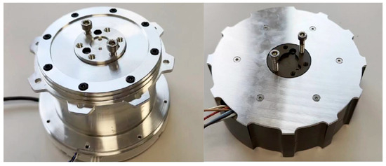
Figure 1.
(Left): assembled in-runner; (right): assembled out-runner.
3. Testing
Both prototypes were tested in two internal functional tests (motor test bench and climate chamber tests) and an external vibration test to validate their design and find an optimal combination for the final iteration.
3.1. Motor Test Bench
For the functional tests, a motor test bench at DFKI was used. In the test bench, the motor is connected to an electric brake via couplings with an intermediate torque sensor. The braking force can then be adjusted as required.
No-load and load tests were carried out to characterize the prototypes, with a further distinction made in the load tests between motor stall and rotation tests. In the no-load tests, the motor was not connected to any load, and the static friction of the motor was determined via the current required to turn the motor. The maximum speed of the motor can also be determined in this way. For the load tests, the motor stall tests were carried out first. The brake was set to a very high resistance, which could brake the motor in any case. The motor’s current was then increased step by step, and the measured torque was recorded. This allows the ratio of current to torque to be determined. During the rotation tests, the braking load was changed step by step in order to determine the ratio of torque to speed. The efficiency of the motor was also determined with the help of the input and output power. At the same time, the temperatures in the motor and on the outer housing were evaluated during the tests in order to observe the thermal behavior of the motors.
3.2. Climate Chamber
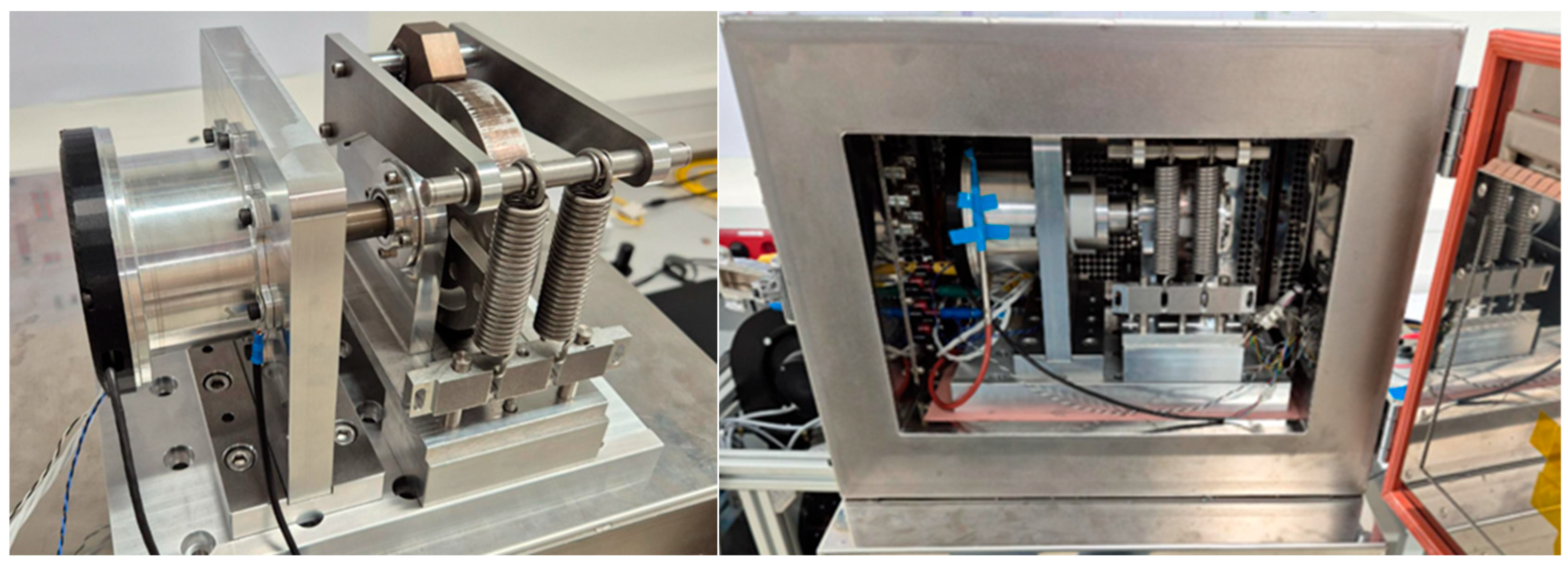
The functional tests in the climatic chamber were based on the operating temperatures provisionally planned for the thermal vacuum tests (−20–80°C). The test started at the lowest temperature and then increased in 5°C steps until the maximum temperature was reached. At each temperature change, a waiting time of 15 min was observed to allow the new temperature to adjust in the chamber. Similarly to the tests in the motor test bench, a no-load and a load test were also carried out here. In the no-load test, the aim was to determine the change in the internal friction of the motor at different temperatures. In the load tests, a load (nominal torque of 10 Nm) was to be applied using a spring-loaded mechanical brake (Figure 2), allowing the efficiency of the motor to be determined at different temperatures. The current required for a specified speed was then measured in both tests.
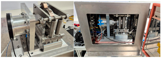
Figure 2.
(Left): Mechanical brake, where force can be set with springs; (right): open climate chamber.
3.3. Vibration Tests
We decided to carry out vibration tests for the prototypes in addition to the internal functional tests. This is intended to test the design principles used for vibration loads in order to validate them for the final iteration.
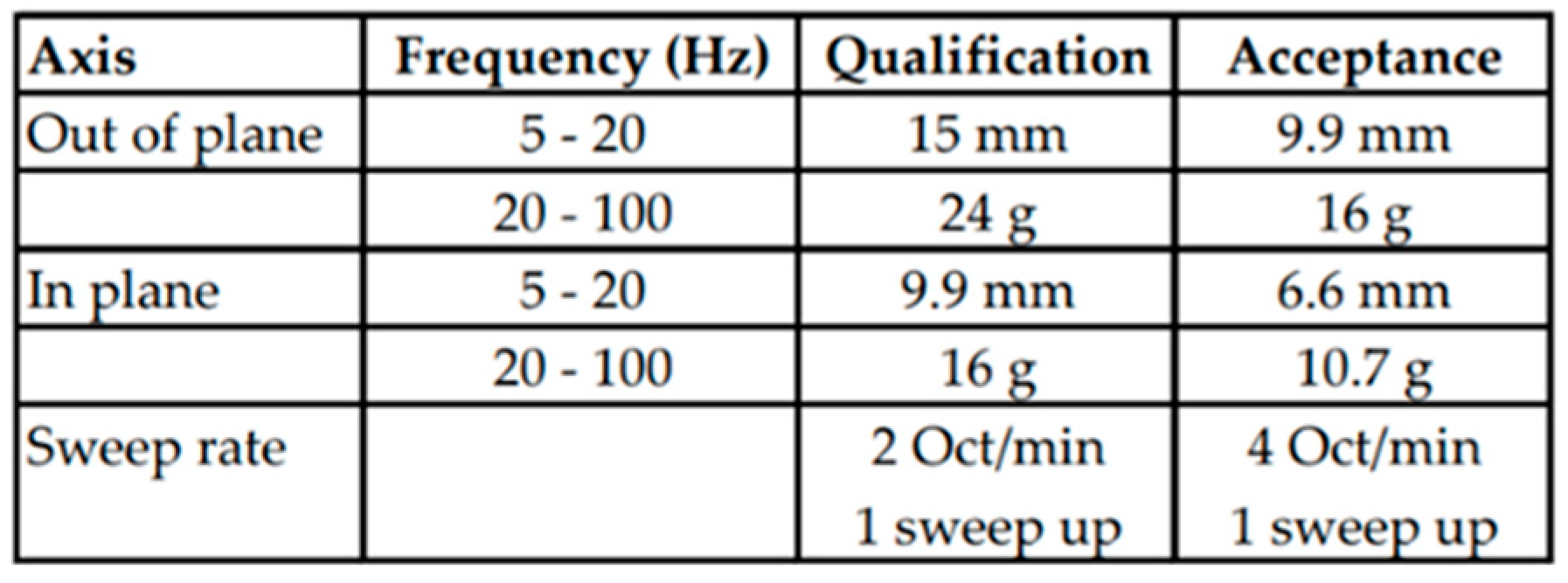
The loads were based on the ECSS standards (ECSS-E-HB-32-26A [9]). For the sine loads, the qualification values for masses below 100 kg were used (Figure 3), and for the random vibrations, the loads were determined using the mass of the components [9] (p. 240).
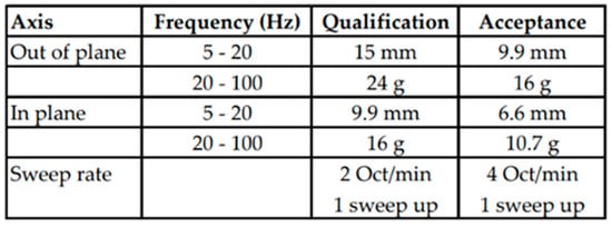
Figure 3.
Suggested sine loads for masses under 100 kg [9] (p. 203).
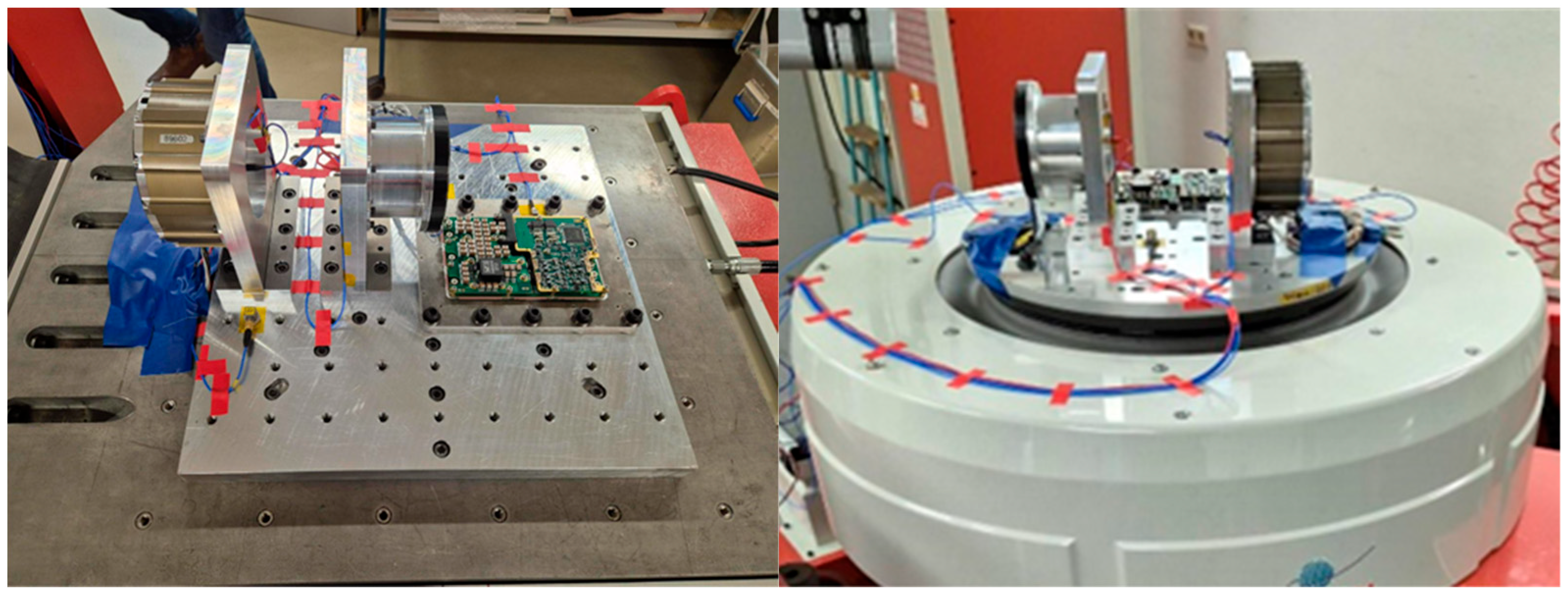
The tests were carried out at Zarm Technik AG, with both motors attached to the vibrating table at the same time. The first iteration of the electronics was also tested. During the tests, the components were loaded in each axis direction. First, a resonance search run was carried out, then the sine loads and finally the random vibrations. Then, the direction was changed and the process started again from the beginning. A functional test of the motors was carried out before/after each run in one axis direction in order to test the functionality after the vibration loads. For this purpose, 3 different current commands were given and compared with the actual current consumption. A lower actual consumption compared to the command value means that the maximum speed has already been reached. If the consumption is now significantly higher after the tests, this may indicate higher friction or damage to some parts. In addition, a speed was specified and the current required for this was measured. The test setup is shown in Figure 4.
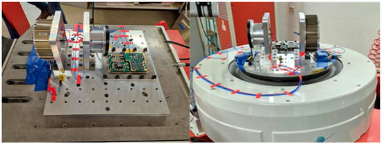
Figure 4.
(Left): horizontal installation of the motors and electronics on the vibrating table; (right): vertical installation.
4. Results and Conclusions
This chapter presents the results of the three different functional tests and then draws a conclusion for the further use of the results in a final iteration.
4.1. Motor Test Bench Results
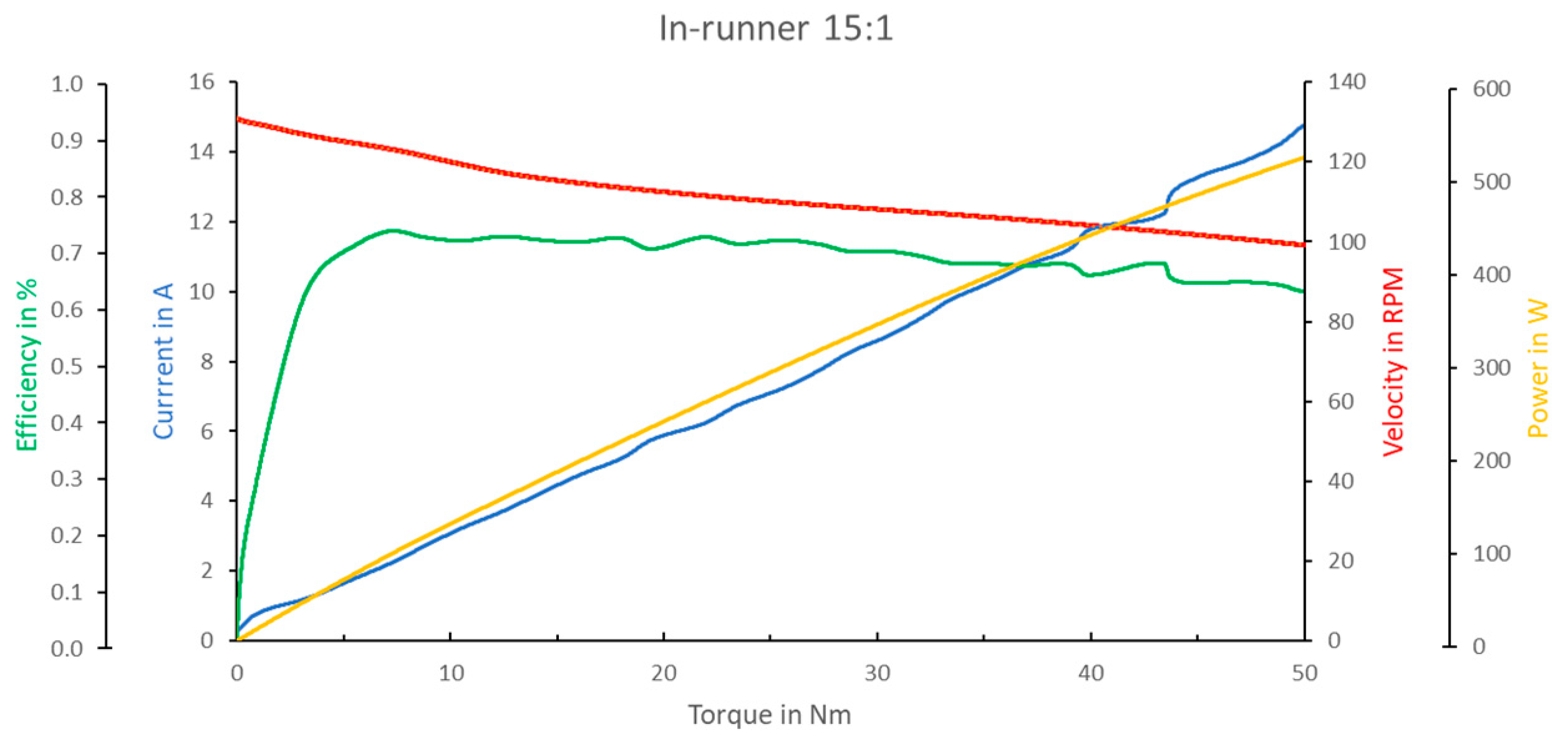
The data obtained during the tests were then evaluated and used to create motor characteristics for both prototypes (Figure 5 and Figure 6). Only the 15:1 reduction is shown, as the curves for the 11:1 reduction were very similar, only with higher values for speed, current and power.

Figure 5.
Motor characteristics of the in-runner; 15:1 reduction.
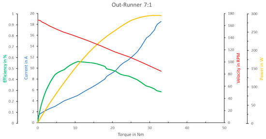
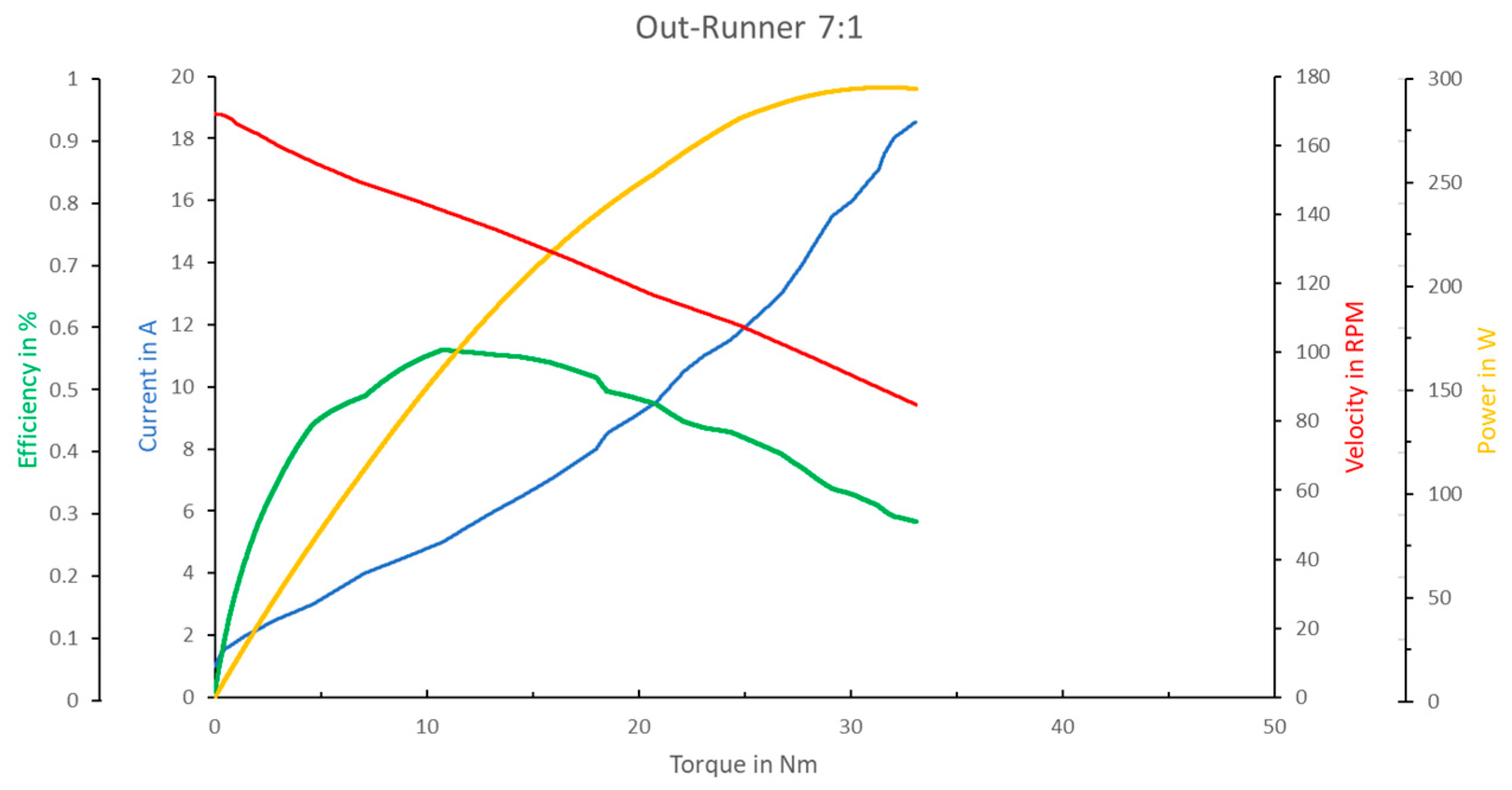
Figure 6.
Motor characteristics of the out-runner; 7:1 reduction.
The results show that the in-runner has a higher efficiency of approx. 73% in the nominal range (10 Nm) compared to only approx. 58% for the out-runner. It can also be seen that significantly higher torques can be achieved with the in-runner at a comparably high speed and efficiency, while the efficiency and speed of the out-runner drops sharply with increasing torque, and the motor can no longer be operated from approx. 35 Nm. On the one hand, this can be attributed to manufacturing deficiencies, which were a problem with both motors, but were even more devastating with the out-runner. However, the temperature measurements also showed that the out-runner heats up significantly more than the in-runner, which also speaks for the large power loss. In addition to the design of the respective stators, this may also be related to the advantage of the in-runner, which enables a direct connection of the stator to the outer part of the housing and thus more efficient heat dissipation, while the out-runner requires a less optimal positioning of the stator in the housing. The in-runner did not have any temperature issues, even at peak currents.
4.2. Climate Chamber Results
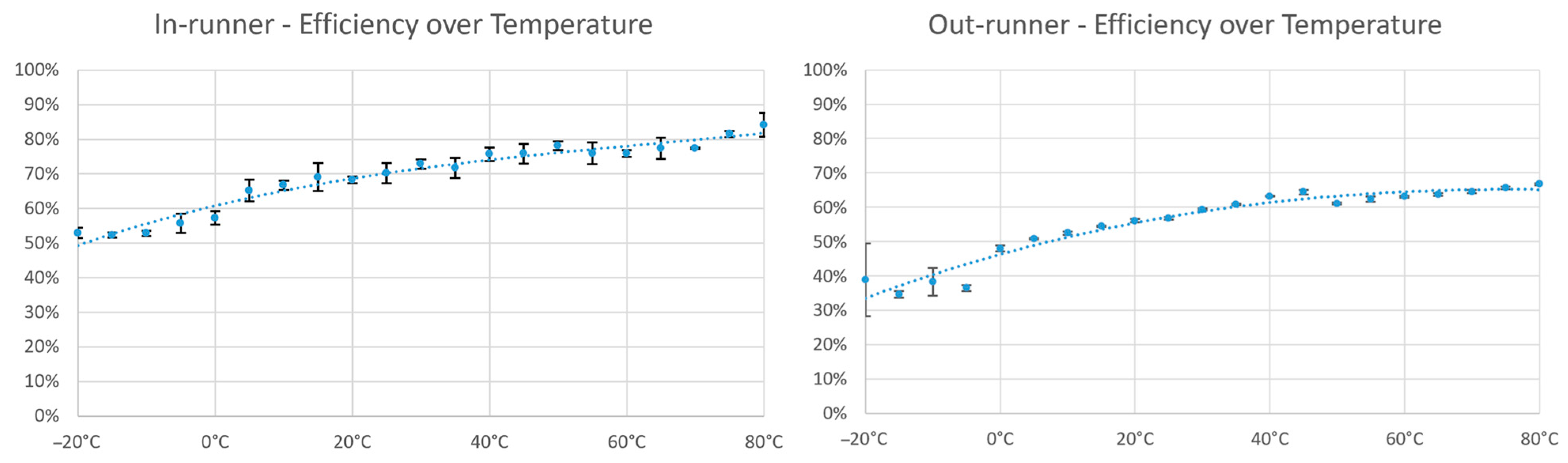
The evaluation showed a drop in efficiency with falling temperature for both motors, which was to be expected due to the higher viscosity of the used grease at lower temperatures. In addition, both motors showed an increase in efficiency with increasing temperature. This suggests that in nominal operation, the motors themselves do not heat up enough for a significant loss of efficiency, and that the ambient temperature of 80 °C does not yet pose a problem. However, this initially only applies under atmosphere and must also be tested under vacuum in the final iteration.
A comparison between the in-runner and out-runner also shows a slightly better performance of the in-runner. Here, the efficiency at low temperatures does not fall as sharply as that of the out-runner and, in addition, a stronger saturation of the curve can already be seen with the out-runner compared to the in-runner at high temperatures (Figure 7).
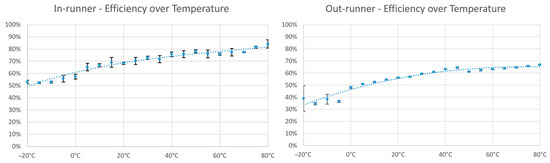
Figure 7.
Evaluation of the efficiency of the in-runner and out-runner at different temperatures with standard deviation.
4.3. Vibration Tests Results
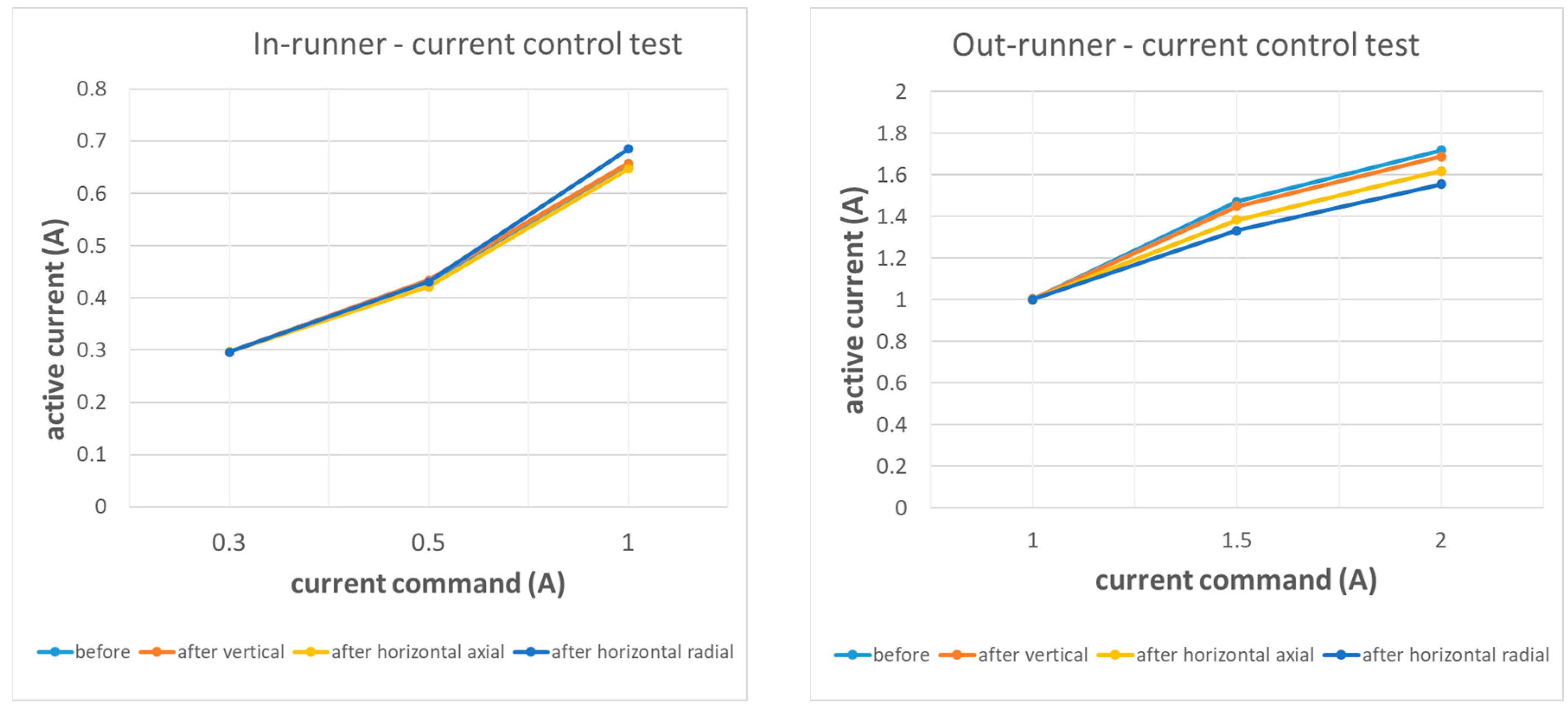
The evaluation of the in-runner showed virtually no change in power consumption (Figure 8), and a subsequent inspection of the motor did not reveal any damage. Accordingly, the in-runner passed the tests.
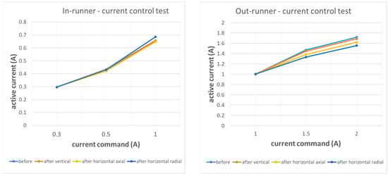
Figure 8.
Comparison of the current command and current consumption for three different currents at different times on the in-runner and out-runner.
The current values of the out-runner even improved during the tests (Figure 8). This may be due to the fact that tensions in the motor were released by the vibrations. But during the inspection of the motor, it was found that one of the bearing preload diaphragms was damaged, which could also be a reason. However, it is not clear whether the diaphragm spring was damaged before the tests or as a result of the tests. In conclusion, it is therefore not possible to say with certainty whether the out-runner passed the vibration tests. However, it can be concluded that the preload diaphragm is a critical component that should be designed to withstand the loads.
The electronics were tested for its functions before and after the tests, and no changes were noticed. Accordingly, the electronics also passed the vibration tests.
4.4. Conclusions
In conclusion, it can be summarized that the in-runner performed better than the out-runner in all the tests carried out. This is partly due to the inadequate manufacturing of the out-runner; however, the out-runner also performed worse thermally than the in-runner, which can be attributed to its unfavorable positioning in the housing and the different stator design. In addition, the vibration tests proved the soft preload design to be suitable, provided the preload elements are designed to withstand the loads.
Since thermal behavior is an essential factor for this space application, it was sufficient to select an in-runner design for the final iteration, despite the differences in manufacturing quality, complicating the comparability. However, further optimizations are necessary in order to increase the efficiency of the motor as much as possible.
5. Final Iteration
For the development of the final iteration, the requirements were first reconsidered in order to enable a clear design of the motor based on a potential mission scenario. Since there is no real mission yet, an example scenario was created, to start with a design. The scenario is a dynamic walking robot for use on the lunar surface. Accordingly, the temperature range was assumed to be −30–85 °C in operation and −40–120 °C out of operation, which corresponds to approx. 10 days on the lunar surface at latitude 0° (6 of these days in operation and 4 out of operation) [10]. For the thermal vacuum tests, an additional test of −20–60 °C in operation and −30–80 °C out of operation can be carried out as an alternative, which corresponds to the same running time on the lunar surface at latitude 40° [10]. Furthermore, an example weight of 40 kg was assumed for the robot, whereby in addition to the 12 motors and electronics, capacities for payload would still be available. Protection against the fine lunar dust is to be neglected for the time being, as important points such as extreme temperatures, vacuum, EMC and vibration loads should be in the foreground at this stage.
In order to determine the forces required for such a motor, a simulation of a 40 kg example robot under moon gravity was carried out, with Gazebo used as a simulator and ROS2 Humble as a control framework. Various motion sequences and load cases were simulated, and the necessary forces on the motor and the loads occurring were determined. A distinction was made between slow walking, running, jumping and an angled fall from a height of 200 mm. Adding safety factors (1.5–3) resulted in the following requirements:
- Nominal torque: 8 Nm;
- Peak torque: 30 Nm;
- Speed: 40 rpm (slow walking), 200 rpm (running).
Based on the requirements, the design of the final iteration could be implemented. To begin with, a combination of a motor and a gearbox had to be selected that met the requirements. As the Robodrive ILM 85 × 23 in-runner motor by TQ-Systems GmbH (Seefeld, Germany) was able to prove itself in the prototype tests, especially thermally, it was decided to use this motor again. The gearbox was to be reduced to a single-stage planetary gearbox to increase efficiency, improve impact mitigation and increase backdrivability. The planetary gearbox PLE40 with a reduction ratio of 7:1 from Neugart GmbH (Kippenheim, Germany) was selected, which is made of vacuum-compatible material. This can transmit the torques specified in the requirements with a small installation size (40 mm outer diameter), which fits into the interior of the motor to save space. For installation in the motor, the gearbox is provided in its individual components (ring gear, planet carrier, sun, planets and needle bearing) so that it can be integrated into the motor in the design.
It was also decided to use a back-to-back angular contact ball bearing arrangement with a soft preload via diaphragm springs for the final iteration. This offers advantages in the event of possible thermal deformation due to extreme temperatures, and was already able to withstand the vibration loads in the in-runner prototype without damaging the bearing. For the final iteration, in contrast to the prototype, a diaphragm spring is also to be used on the encoder side, as this can be integrated in a space-saving manner.
A D-SUB DB-5W5 connector is used for the power supply, as well as a 9 position Micro-D connector for the motor’s encoder and temperature sensors. Both have been selected in accordance with ECSS standards, and space-qualified, EMC-protected versions are used.
The encoder used is a space-grade version of the VLP60 by Netzer Precision Position Sensors A.C.S. Ltd. (Misgav, Israel) Compared to the VLP100, which was installed in the prototypes, this has a smaller installation size and has already been tested by the manufacturer for radiation exposure.
In general, the final iteration will use space-grade material, i.e., material with low outgassing, and other factors such as “cold welding” will be prevented by anodizing all parts. In addition, the outer parts are gold-anodized, which gives the housing high emission and low absorption at the same time [11]. This helps with thermal behavior, as the internal heat can be radiated and the external radiation reflected. The housing is designed to maximize surface area without adding too much extra weight to further aid the radiation of internal heat.
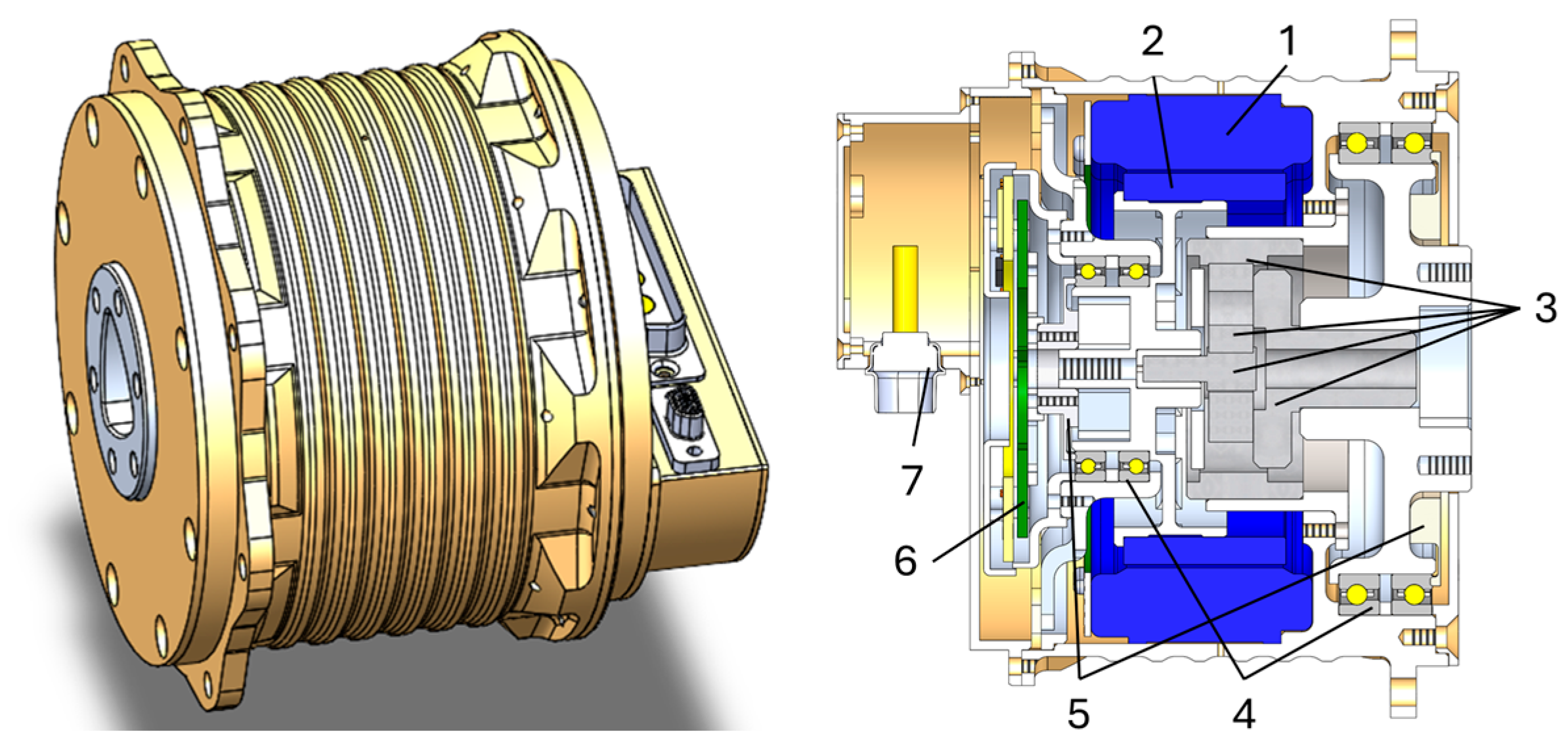
Figure 9 shows the developed design of the final iteration and Table 1 the motor characteristics compared to the prototypes.
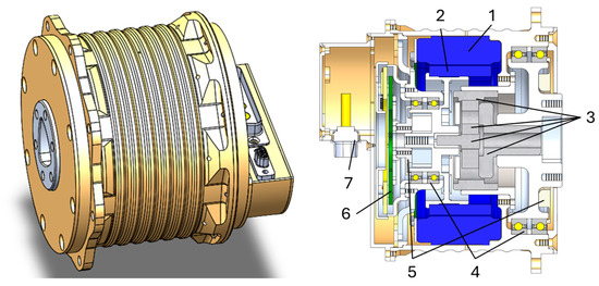
Figure 9.
Design of the final iteration, isometric and cut view. 1: Stator. 2: Rotor. 3: Planetary gearbox components. 4: Angular bearings. 5: Diaphragm spring. 6: VLP60 encoder. 7: Connector.

Table 1.
Theoretical motor characteristics of final iteration and prototypes (updated from [6]).
6. Outlook
The next step is to assemble the final iteration in a clean room environment. It will then undergo the same functional tests as the prototypes. In addition to the vibration tests, further environmental tests are planned, including thermal vacuum and EMC tests, to finally move towards TRL level 5 for the motor.
Author Contributions
Writing, J.E.; motor testing, J.E. and Z.Z.; motor design, J.E. and Z.Z.; supervision, F.K. All authors have read and agreed to the published version of the manuscript.
Funding
This research was funded by the Federal Ministry for Economic Affairs and Climate Action, as well as German Aerospace Center (DLR), grant numbers 50RA2107 and 50RA2108.
Institutional Review Board Statement
Not applicable.
Informed Consent Statement
Not applicable.
Data Availability Statement
Data is contained within the paper.
Conflicts of Interest
Author J.E., Z.Z. and F.K. was employed by DFKI GmbH. The authors declare that the research was conducted in the absence of any commercial or financial relationships that could be construed as a potential conflict of interest. The authors declare no conflicts of interest. The funders had no role in the design of this study; in the collection, analyses, or interpretation of the data; in the writing of the manuscript; or in the decision to publish the results.
References
- Katz, B.; Carlo, J.; Kim, S. Mini Cheetah: A Platform for Pushing the Limits of Dynamic Quadruped Control. In Proceedings of the 2019 International Conference on Robotics and Automation (ICRA), Montreal, QC, Canada, 20–24 May 2019; pp. 6295–6301. [Google Scholar] [CrossRef]
- Unitree. Available online: https://www.unitree.com/a1/ (accessed on 12 September 2024).
- Valsecchi, G.; Weibel, C.; Kolvenbach, H.; Hutter, M. Towards Legged Locomotion on Steep Planetary Terrain. In Proceedings of the 2023 IEEE/RSJ International Conference on Intelligent Robots and Systems (IROS), Detroit, MI, USA, 1–5 October 2023; pp. 786–792. [Google Scholar] [CrossRef]
- Miki, T.; Lee, J.; Hwangbo, J.; Wellhausen, L.; Koltun, V.; Hutter, M. Learning robust perceptive locomotion for quadrupedal robots in the wild. Sci. Robot. 2022, 7, eabk2822. [Google Scholar] [CrossRef] [PubMed]
- Valsecchi, G.; Liconti, D.; Tischhauser, F.; Kolvenbach, H.; Hutter, M. Preliminary design of actuators for walking robot on the moon. In Proceedings of the 16th Symposium on Advanced Space Technologies in Robotics and Automation (ASTRA), Noordwijk, The Netherlands, 1–2 June 2022. [Google Scholar]
- Yüksel, M.; Brinkmann, W.; Eisenmenger, J.; Wiedemann, H.; Kien, I.; Mulsow, N.; Kirchner, F. Toolbox of Modular Components to Demonstrate Application-Specific Configurable Space Robots. In Proceedings of the 17th Symposium on Advanced Space Technologies in Robotics and Automation (ASTRA), Leiden, The Netherlands, 18–20 October 2023. [Google Scholar] [CrossRef]
- Brinkmann, W.; Schilling, M.; Chowdhury, P.; Eisenmenger, J.; Benz, J.; Langosz, M.; Li, J.; Michelson, E.; Yüksel, M.; Kirchner, F. Towards sustainable space exploration: Designing an AI powered modular toolbox for future planetary exploration. In Proceedings of the 14th EASN International Conference on Innovation in Aviation & Space Towards Sustainability Today & Tomorrow, Thessaloniki, Greece, 8–11 October 2024. [Google Scholar]
- Mulsow, N.; Sonsalla, R.; Schöberl, P.; Stark, T.; Kirchner, F. Design and environmental testing of the dfki-x robotics joint for space applications. In Proceedings of the 18th European Space Mechanisms and Tribology Symposium, (ESMATS), Online, 20–24 September 2021. [Google Scholar]
- ECSS-E-HB-32-26A; Space engineering: Spacecraft Mechanical Loads Analysis Handbook. European Cooperation for Space Standardization: Noordwijk, The Netherlands, 2013.
- Williams, J.-P.; Paige, D.A.; Greenhagen, B.T.; Sefton-Nash, E. The global surface temperatures of the Moon as measured by the Diviner Lunar Radiometer Experiment. Icarus 2017, 283, 300–325. [Google Scholar] [CrossRef]
- Henninger, J.H. Solar Absorptance and Thermal Emittance of Some Common Spacecraft Thermal-Control Coating; NASA Reference Publication 1121; National Aeronautics and Space Administration, Scientific and Technical Information Branch: Washington, DC, USA, 1984. [Google Scholar]

Disclaimer/Publisher’s Note: The statements, opinions and data contained in all publications are solely those of the individual author(s) and contributor(s) and not of MDPI and/or the editor(s). MDPI and/or the editor(s) disclaim responsibility for any injury to people or property resulting from any ideas, methods, instructions or products referred to in the content. |
© 2025 by the authors. Licensee MDPI, Basel, Switzerland. This article is an open access article distributed under the terms and conditions of the Creative Commons Attribution (CC BY) license (https://creativecommons.org/licenses/by/4.0/).