Abstract
This study investigates the effect of active and passive flow control devices on the aerodynamic behavior and stability of a Blended-Wing-Body (BWB) Unmanned Air Vehicle (UAV), emphasizing the low-speed segments of a typical flight. Vortilons, which are small fins placed on the leading edge of the wing, generate vortices that delay the appearance of spanwise flow and consequently the appearance of pitch break. Belly flaps are located on the underside of the UAV and can enhance the lift, while they produce a nose-up pitching moment. Seven different configurations are examined using high-fidelity Computational Fluid Dynamics (CFD) over a range of angles of attack to address the effect of each device on the lift and drag forces and the pitching moment of the UAV. Based on these results, the low-speed performance of the platform is evaluated by calculating the minimum speed, the take-off distance, and the maximum lift to drag ratio, while the elevon deflection required for the take-off rotation of the UAV is also assessed.
1. Introduction
A Blended-Wing-Body (BWB) configuration was introduced as a novel and highly efficient fixed wing aircraft configuration by Liebeck [1] in the early 2000s. It differs from a conventional aircraft by having an indistinctive and smooth blend between the wing and the main body of the aircraft. This configuration has been selected in various applications on different aircraft classes and missions, like high-speed airliners, cargo transportation aircraft, and Unmanned Air Vehicles (UAVs). The latter two categories can benefit significantly by the selection of a BWB configuration, as it offers larger internal volume, leading to the ability to carry a more useful payload and more fuel compared to a traditional tube-and-wing configuration. As BWB aircraft are mostly tailless configurations, the designers are led to make some specific design choices. The most common choice, which can be observed even by an untrained eye, is the use of a sweep angle on the wing. This choice can be found in BWB aircraft in both low- and high-subsonic-speed regimes, as it is not only used as a way to reduce the wave drag of the platform, but also to achieve adequate stability. Sweeping the wing aftwards improves the longitudinal and lateral stability by moving the aerodynamic center of the aircraft backwards, increasing the dihedral effect. Additionally, as the control surfaces are placed towards the wing tip, the effective arm of the moment produced by their deflection is also increased on the aftswept wing, enhancing the overall controllability of the platform.
Despite the advantages of the aftsweep for stability, the increase in the sweep angle of the wing can lead to an undesired tendency to produce a positive pitching moment (pitch-up) as the angle of attack increases, which can potentially result in the complete loss of control. This destabilizing behavior is also called unstable pitch break and is commonly observed in aftswept wings with a high Aspect Ratio (AR) [2]. Additionally, control is compromised as the control surfaces operate within the stalled region. These issues pose significant risks to the safe operation of BWB platforms during low-speed flight phases, such as take-off and landing.
To enhance the low-speed performance of the BWB configuration, different active and passive flow control devices can be used. Passive flow control devices include wing-fences [3], vortex generators [4], dog-tooth configurations [5], and vortilons [6]. The wing-fences stop the development of the spanwise flow by physically obstructing its path, forcing it to go in parallel with the fence. The remaining configurations create a vortex that flows over the suction side of the wing. This hampers the spanwise flow development, creating a pseudo-fence. Even though wing-fences deal with the spanwise flow more efficiently, the other methods, e.g., those using vortilons, have a minimum drag penalty during a typical flight.
Regarding the active flow control devices, trailing-edge flaps cannot be used to enhance the overall lift and thus the performance. The use of trailing-edge flaps creates a strong pitching down moment, which cannot be absorbed by the control surfaces. The feasible active flow control alternatives are leading-edge slats and belly flaps. Leading-edge slats successfully delay or prevent the appearance of an unstable pitch break [7]. The slats delay spanwise flow on the suction side of the wing in two ways: by increasing airspeed through the slat–wing gap, which maintains attached flow at higher angles of attack, and by generating vortices along their sides, which act as pseudo-wing-fences to inhibit spanwise flow. Belly flaps [8] enhance the overall lift of the platform, while also producing a nose-up pitching moment, which is advantageous for take-off. This effect arises from a pressure differential created across the belly flaps—positive pressure before the flap and negative pressure after it—which not only increases lift but also counteracts nose-down tendencies.
In this study, the vortilons and the belly flaps are selected as the passive and the active flow control devices, respectively, to assess their effect on the low-speed performance and the stability of a BWB UAV. Four different configurations of vortilons and three different configurations of belly flaps are investigated through high-fidelity Computational Fluid Dynamics (CFD) simulations to evaluate the effect on the lift, the drag, and the pitching moment behavior of the UAV. Then, the performance of the examined configurations is quantified through four performance metrics, which are the speed at which the UAV encounters pitch-break (VPB), the maximum lift to drag ratio (L/Dmax), the take-off distance, and the deflection of the elevons required to successfully rotate the UAV during take-off. Finally, these metrics are compared to the corresponding metrics of the baseline platform.
2. Baseline Platform
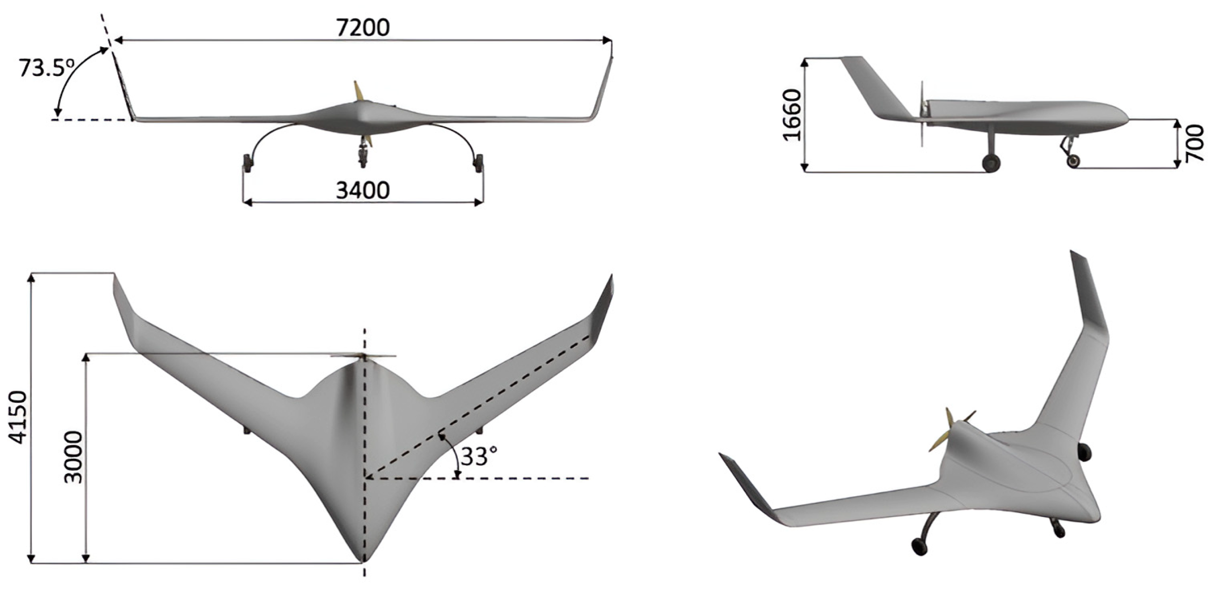
The baseline platform for this study is a fixed-wing BWB UAV configuration (Figure 1), which was developed through a conceptual and preliminary design study [9], supported by aerodynamics research and parametric studies at the Laboratory of Fluid Mechanics and Turbomachinery (LFMT) at Aristotle University of Thessaloniki (AUTH), Greece. It is used as the reference platform for the EURRICA project. The design and sizing process was implemented using specialized in-house tools, along with commercial software for the aerodynamic modeling, while the overall design was made with full compliance with airworthiness regulations. The UAV wing section has a sweep angle of 33 degrees and an aspect ratio of 8. More details about the design procedure, the tools, and the layout can be found in [9]. The operating specifications of the baseline platform resemble those of tactical UAVs, which are described in [10] and presented in detail in [9]. Some basic geometric, mass, and performance data relevant to this study are presented in Table 1.
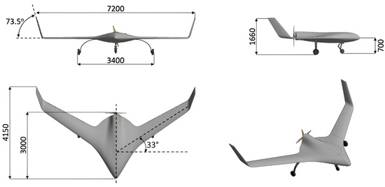
Figure 1.
External layout of the tactical BWB UAV baseline platform.

Table 1.
Baseline BWB UAV platform specifications.
3. Tools and Methods
3.1. Flow Control Devices
3.1.1. Vortilons
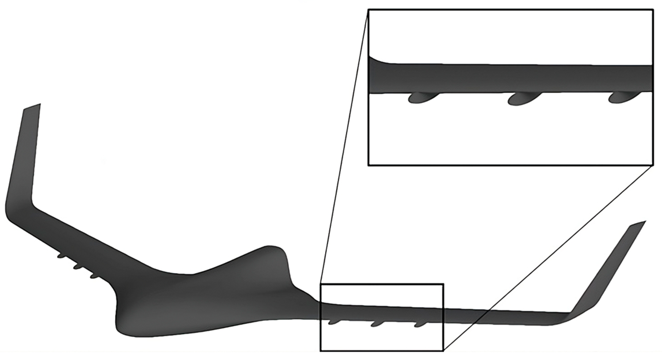
Vortilons are small, pylon-shaped surfaces that are placed on the leading edge of the wing. Their side profile is designed based on the vortilons that are placed in other aircraft [11], and they are placed at different locations across the span of the wing. Ultimately, four different configurations are investigated in the current study. The first three configurations refer to the placement of a single vortilon at 40%, 50% and 60% of the semi-span of the wing, respectively. The fourth configuration is the concurrent placement of three vortilons in the aforementioned locations (Figure 2).
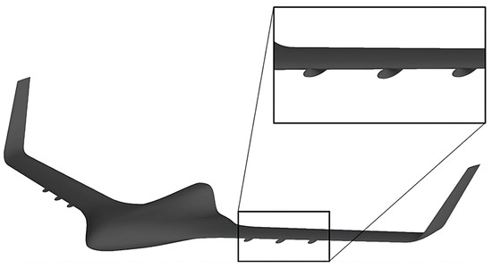
Figure 2.
Configuration with three vortilons on the wing.
3.1.2. Belly Flaps
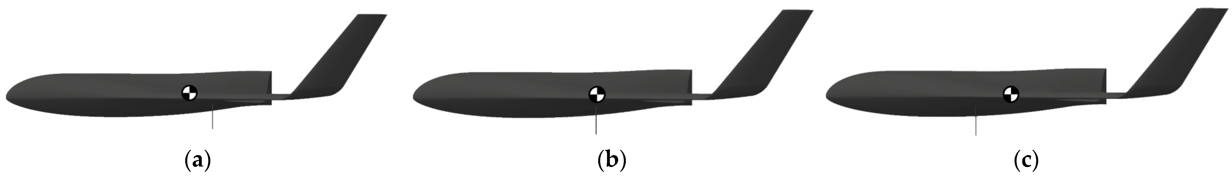
Belly flaps are orthogonally shaped surfaces that are placed vertically on the underbody (belly) of the platform. Their working mechanism involves the creation of a pressure differential before (positive pressure) and after (negative pressure) the flap, which results in a significant lift enhancement. For the purposes of this study, the profile of the flap is designed based on geometries of similar studies and it is placed on three different longitudinal positions compared to the center of gravity (Figure 3). The first configuration has the belly flap forward from the center of gravity (towards the nose), the second has the belly flap on the center of gravity position, and the latter one has the belly flap aftwards from the center of gravity.
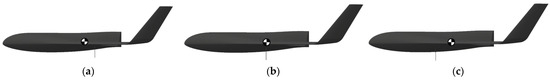
Figure 3.
Belly flaps configurations: (a) forward from the CG, (b) on the CG, and (c) aftwards from the CG.
3.2. CFD Methodology
To investigate aerodynamic behavior, high-fidelity CFD modeling is conducted by solving the steady-state Reynolds Averaged Navier–Stokes (RANS) equations with the adoption of the two-equation k-ω SST turbulence model [12], which is widely used in aeronautical applications. The CAD models of the examined configurations are imported into BETA ANSA pre-processing software (v19.1.0, Root, Switzerland) for control volume discretization and computational mesh generation. A mix of structured and unstructured meshing is employed: unstructured mesh is used for most of the domain to handle complex 3D regions like the ones encountered between the slat and main body, and structured mesh is used near the UAV surface to adequately capture boundary layer gradients. The y+ parameter is generally kept under 1 on the surface of the wing, while it is acceptable to have y+ values under 5 locally as the angle of attack increases, ensuring accurate viscous sublayer modeling [13]. Surface element sizes ranged from 1 mm at the trailing edge to 30 mm in central body regions, with leading-edge curvature resolved with at least 25 elements for precision.
3.3. Performance Metrics
The performance of the platform is assessed using four distinctive metrics: the speed at which the pitch break of the UAV appears, the take-off distance, the deflection required for the rotation of the UAV during the take-off ground roll, and finally the maximum lift to drag ratio. The first three metrics are evaluated for the entirety of the examined configurations, while the latter one is only assessed for the vortilons that, as passive flow control devices, affect the performance of the aircraft for the entirety of a flight.
The speed at which the pitch break appears is calculated in the same manner as the stall speed of an aircraft, but instead of selecting the lift coefficient at which the aerodynamic stall appears, the coefficient at which the pitch break occurs is selected. The take-off distance is calculated during the ground roll of the UAV using the equations of motion and this metric describes the runway that is required to successfully take off and clear an obstacle of a specific height. During the take-off flight segment, the deflection of the elevons required to achieve sufficient angular acceleration about the aircraft main landing gear in order to perform take-off rotation in a determined time limit is calculated. Finally, the maximum lift to drag ratio is used as a comparative metric for the vortilons, so the impact of their use on range and endurance is assessed. The detailed methodology and the equations for the aforementioned performance metrics are taken from the corresponding aeronautical literature [14,15].
4. Results
The aerodynamic force and moment of the seven examined configurations and the baseline platform are extracted from the CFD simulations. Figure 4 and Figure 5 present the results of the simulations for the vortilons and the belly flaps, respectively, compared to the baseline platform.

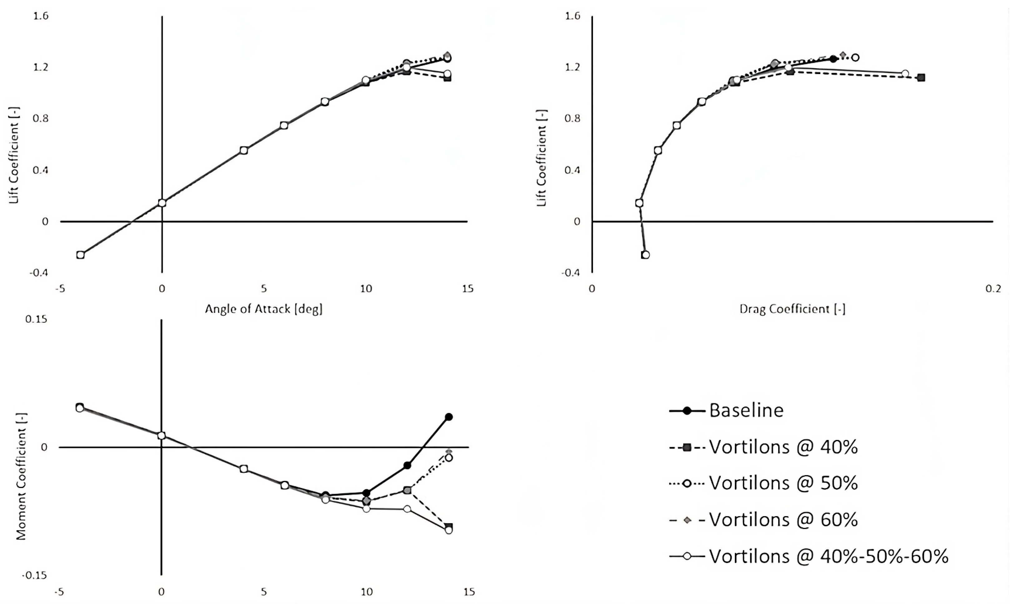
Figure 4.
Aerodynamic behavior with the use of vortilons compared to the baseline platform.

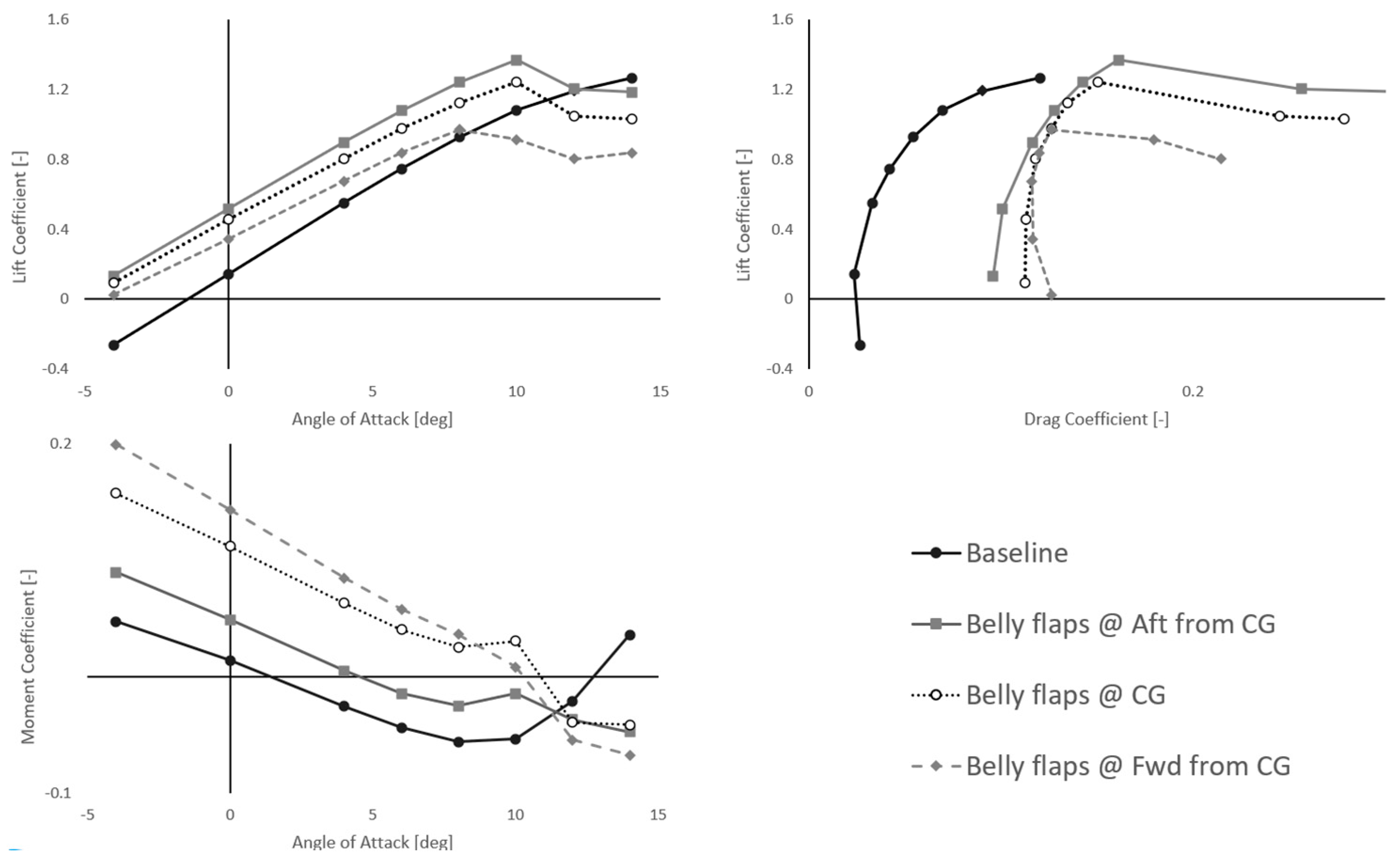
Figure 5.
Aerodynamic behavior with the use of belly flaps compared to the baseline platform.
The use of vortilons seems to alter the aerodynamic properties of the UAV, and this mainly occurs in the non-linear range of angles of attack. All the coefficients examined and, most importantly, the drag coefficient have the same trend in this range of angles of attack, leading to minor effects on the high-speed performance of the UAV. Regarding the high angle of attack regime, the use of vortilons closer to the root of the wing leads to aerodynamic stall, as shown in the top left diagram of Figure 4. This is evident from the fact that both the configurations with the vortilon at the 40% position reach the maximum lift coefficient. The pitching moment coefficient is affected as was expected, as the curve has smoother behavior and the pitch break is delayed by about 2 degrees of angle of attack for the use of a single vortilon, while their combined use not only delays the pitch break’s appearance by a total of 4 degrees of angle of attack, but also causes the break to display stable behavior.
In contrast with the vortilons, the use of belly flaps affects the whole angle of attack regime. At first, as can be seen from the top left and right diagrams of Figure 5, the belly flaps alter the lift and the drag coefficient like a normal flap, meaning that lift is enhanced at low angles of attack with a significant increase in the drag as well. At the higher angle of attack region, the aerodynamic stall occurs earlier than for the baseline platform, but the lift coefficient is only increased when the belly flap is placed aftwards from the center of gravity. The pitching moment coefficient is affected in the way that was initially expected, as a pitch-up moment is produced when the belly flaps are used. The increase in pitching moment is influenced by the flap’s position, with more forward placements producing greater enhancements, while aft positions result in smaller increases. Although placing the flap forward of the center of gravity improves the pitching moment coefficient at lower angles of attack, it negatively impacts overall aerodynamic performance. This forward placement leads to significantly earlier aerodynamic stall, along with the smallest lift increase among all configurations and the highest drag penalty.
The performance metrics are calculated with the maximum take-off weight at sea level conditions for all the configurations and they are compared to the baseline. The results of the performance of the vortilons are presented in Table 2.
Table 2.
Performance metric comparison of the vortilon configurations and the baseline.
The low-speed performance of the UAV is affected positively by the introduction of the vortilons as the pitch break speed and the take-off distance are significantly reduced. The placement of a single vortilon, regardless of its position, causes an average reduction of 7.7% in the pitch break speed, while the take-off distance is reduced by an average of 23%. This similar behavior of the performance with a single vortilon is justified by the minor effect that this device has on the lift coefficient of the UAV and the same delay of 2 degrees of angle of attack on the pitch break appearance. In the case of the combined use of all the three vortilons, the pitch break is delayed by 4 degrees of angle of attack, leading to a better low-speed performance. In particular, the pitch break speed is reduced by 12.08%, while the take-off distance is reduced by 34.19%, compared to the baseline. Both these reductions are quite significant for the overall performance of the platform. The last low-speed performance metric that is assessed in this study, the required elevon deflection to successfully rotate the air vehicle, is unaffected by the introduction of the vortilons. This result is expected, as the aerodynamic behavior of the UAV remains unaltered in the linear range of angles of attack for both lift and the pitching moment. Finally, only for the vortilons, the maximum lift to drag ratio is evaluated as an overall metric to substitute the high-speed performance. As can be seen on the final column of Table 2, this ratio is not affected by the introduction of the vortilons and only a minor reduction appears.
Regarding the belly flaps, the pitch break speed of the UAV (first column of Table 3) decreases when the flaps are deployed in all cases, with a greater reduction observed as the flap is positioned further aft. The belly flap on its most aft position reduces the pitch break speed by 13.55%, which is a result of the higher maximum lift coefficient that can be achieved, while the lowest difference is seen for the most forward position at 2.33%. This small difference results from the premature aerodynamic stall that occurs in the same angle of attack with the baseline configuration, combined with a small maximum lift coefficient which is approximately the same as the one of the baselines. In this case, this small deviation of the pitch break speed, combined with the lower lift increment at low angles of attack and the anticipated drag increment, has a significant effect on the take-off distance, as this configuration is the only one where the distance is increased. In contrast, the placement of the flap on the CG and aft from the CG reduces the take-off distance significantly (14.9% and 31.04% respectively), which is comparable to the effect of vortilons. The final metric evaluated in this study, the required elevon deflection, is expected to be most significantly affected by the use of belly flaps. As is evident from the results in Table 3, the reduction in the deflection angle is significant after the deployment of the flaps. When the flaps are placed aft from the CG, the reduction in the deflection is calculated to be 18.4%, which is the smallest of the three configurations, while the forward placement appears to have the biggest impact with a 50.76% smaller angle, meaning that the belly flaps serve their intended purpose successfully.
Table 3.
Performance metrics comparison of the belly flaps configurations and the baseline.
Summarizing, the use of vortilons has a major impact on the reduction in the pitch break speed and of the take-off distance, while their effect on the maximum lift to drag ratio and the required deflection of the elevons is insignificant, with the best configuration being the combination of all three vortilons along the wingspan. Also, as vortilons are small surfaces with a small weight penalty, they can easily be considered as a way to improve the low-speed performance of the UAV without affecting the overall flight behavior of the platform. Regarding the belly flaps, placing them forward past the center of gravity offers the greatest reduction in elevon deflection. However, their poor performance in the other two metrics makes this configuration an impractical solution. The best balance of the three considered metrics is produced via the placement of the belly flaps on the longitudinal position of the CG, which could be recommended for further evaluation considering the structural and internal layout implications that may arise from its use.
5. Conclusions
This study conducted a CFD-aided investigation of vortilons and belly flaps on a BWB UAV baseline platform, aiming to enhance its low-speed performance. Vortilons are primarily utilized to delay the onset of unstable pitch break, while belly flaps are analyzed for their impact on pitch break and their potential to reduce the required elevon deflection during take-off rotation. Four vortilon configurations and three belly flap configurations are examined using computational modeling to determine the associated aerodynamic and stability coefficients. These coefficients are then used to evaluate the low-speed performance of the UAV based on three metrics: the speed at which pitch break occurs, the required take-off distance, and the elevon deflection needed. Additionally, for the vortilons, the maximum lift to drag ratio is also assessed. The main conclusions of this study are as follows:
- ▪
- Vortilons can be used to successfully reduce the appearance of unstable pitch break, with a minor impact on the performance at lower angles of attack.
- ▪
- The concurrent use of three vortilons across the semi-span of the wing leads to the biggest decrease in the pitch break speed and the take-off distance, falling by 12.08% and 34.19%, respectively.
- ▪
- The use of vortilons has a negligible impact on the required deflection of the elevons and the maximum lift to drag ratio.
- ▪
- Belly flaps have a greater impact on pitch break speed and take-off distance when positioned further aft, whereas placing them in the most forward position increases the take-off distance.
- ▪
- The configuration with the most balanced enhancement of the low-speed performance is the placement on the CG, with reductions of 9.10% in the pitch break speed, 14.9% in the take-off distance, and 41.09% on the required elevon deflection.
The next steps in the research presented will be focused on the study of the additional geometrical parameters of the vortilons and the impact of belly flaps on the low-speed performance. Regarding the vortilons, more thorough investigation needs to be performed on the higher-speed flight segments, while for the belly flaps further simulations incorporating ground effects could be conducted to evaluate their influence on the required elevon deflection. Finally, the structural implementation of the use of belly flaps can also be investigated, with emphasis on the required internal layout modifications, actuation, and the corresponding weight penalty.
Author Contributions
Conceptualization, S.A. and K.A.; methodology, P.P. and S.A.; software, K.A.; validation, S.A., P.P. and K.Y.; investigation, K.A.; resources, S.A.; data curation, S.A. and K.A.; writing—original draft preparation, S.A. and K.A.; writing—review and editing, P.P. and K.Y.; visualization, S.A. and K.A.; supervision, P.P.; funding acquisition, P.P. and K.Y. All authors have read and agreed to the published version of the manuscript.
Funding
This research received no external funding.
Institutional Review Board Statement
Not applicable.
Informed Consent Statement
Not applicable.
Data Availability Statement
Data available on request due to restrictions related to the details of the baseline platform. The data presented in this study are available on request from the corresponding author.
Acknowledgments
Results presented in this work have been produced using the Aristotle University of Thessaloniki (AUTh) High Performance Computing Infrastructure and Resources.
Conflicts of Interest
The authors declare no conflicts of interest.
References
- Liebeck, R.H. Design of the Blended Wing Body Subsonic Transport. J. Aircr. 2004, 41, 10–25. [Google Scholar] [CrossRef]
- Shortal, J.A.; Maggin, B. Effect of Sweepback and Aspect Ratio on Longitudinal Stability Characteristics of Wings at Low Speeds; Defense Technical Information Center: Fort Belvoir, VA, USA, 1946; NACA TN-1093. [Google Scholar]
- Walker, M.; Bons, J. The Effect of Passive and Active Boundary-Layer Fences on Swept-Wing Performance at Low Reynolds Number. In Proceedings of the AIAA Scitech 2018 Forum, Kissimmee, FL, USA, 8–12 January 2018. [Google Scholar]
- Goharshadi, M.; Mirzaei, M. Delaying the Stall of a Low-Wing Aircraft Using a Novel Powerful Vortex Generator. Inventions 2022, 7, 95. [Google Scholar] [CrossRef]
- Jaquet, B.M. Effects of Chord Discontinuities and Chordwise Fences on Low-Speed Static Longitudinal Stability of an Airplane Model Having a 35 Degree Sweptback Wing; Defense Technical Information Center: Fort Belvoir, VA, USA, 1952; NACA-RM-L52C25. [Google Scholar]
- Phillips, E.; Wygnanski, I.J.; Menge, P.M.; Taubert, L. Passive and Active Leading Edge devices on a simple swept back wing. In Proceedings of the AIAA Aviation 2019 Forum, Dallas, TX, USA, 17–21 June 2019; American Institute of Aeronautics and Astronautics: Reston, VA, USA, 2019; p. 3393, NACA-RML52C25. [Google Scholar]
- Antoniou, S.; Kapsalis, S.; Panagiotou, P.; Yakinthos, K. Parametric Investigation of Leading-Edge Slats on a Blended-Wing-Body UAV Using the Taguchi Method. Aerospace 2023, 10, 720. [Google Scholar] [CrossRef]
- Staelens, Y.; Blackwelder, R.; Page, M. Study of belly-flaps to enhance lift- and pitching moment coefficient of a BWB-airplane. In Proceedings of the 25th AIAA Applied Aerodynamics Conference, Miami, FL, USA, 25–28 June 2007. [Google Scholar]
- Panagiotou, P.; Mitridis, D.; Dimopoulos, T.; Kapsalis, S.; Dimitriou, S.; Yakinthos, K. Aerodynamic design of a tactical Blended-Wing-Body UAV for the aerial delivery of cargo and lifesaving supplies. In Proceedings of the AIAA Scitech 2020 Forum, Orlando, FL, USA, 6–10 January 2020. [Google Scholar]
- Verstraete, D.; Palmer, J.L.; Hornung, M. Preliminary Sizing Correlations for Fixed-Wing Unmanned Aerial Vehicle Characteristics. J. Aircr. 2018, 55, 715–726. [Google Scholar] [CrossRef]
- Reynolds, P. Ten Years of Stall Testing. In Proceedings of the Orbital Debris Conference: Technical Issues and Future Directions, Baltimore, MD, USA, 16–19 April 1990. [Google Scholar]
- Menter, F.R. Two-Equation Eddy-Viscosity Turbulence Models for Engineering Applications. AIAA J. 1994, 32, 1598–1605. [Google Scholar] [CrossRef]
- Wilcox, D.C. Turbulence Modeling for CFD, 2nd ed.; DCW Industries: La Canada, CA, USA, 1998. [Google Scholar]
- Raymer, D. Aircraft Design: A Conceptual Approach, 6th ed.; American Institute of Aeronautics and Astronautics: Reston, VA, USA, 2018. [Google Scholar]
- Sadraey, M.H. Aircraft Design: A Systems Engineering Approach; John Wiley & Sons: Hoboken, NJ, USA, 2024. [Google Scholar]
Disclaimer/Publisher’s Note: The statements, opinions and data contained in all publications are solely those of the individual author(s) and contributor(s) and not of MDPI and/or the editor(s). MDPI and/or the editor(s) disclaim responsibility for any injury to people or property resulting from any ideas, methods, instructions or products referred to in the content. |
© 2025 by the authors. Licensee MDPI, Basel, Switzerland. This article is an open access article distributed under the terms and conditions of the Creative Commons Attribution (CC BY) license (https://creativecommons.org/licenses/by/4.0/).