Abstract
With the renewed interest in the Moon, manifested by the growing number of planned missions for the past decade, space agencies are investing in reliable and dedicated lunar communication and navigation systems and services, such as the Moonlight programme of the European Space Agency (ESA), to provide support to all types of lunar users (i.e., surface users, landers and orbiters). In the context of lunar human and robotic exploration, one of the critical phases will be the landing of spacecraft on lunar soil. This type of operation is far from trivial, as shown by the recent crashes such as the one of the Luna25 lander from the Russian Space Agency. A reliable method to position a lander during its descent could be provided by a dedicated lunar navigation system. This paper will focus on what the achievable positioning accuracy is for a lander landing on the Moon’s South Pole using dedicated satellite-based navigation services such as Moonlight. It will be shown that using the LCNS constellation and the altimeter can achieve a sub 50 m accuracy with a 99% confidence interval.
1. Introduction
In recent years, there has been a resurgence of interest in lunar exploration, marked by an increasing number of planned missions and ambitious initiatives aiming to set foot on the Moon once again [,]. To support those endeavours, space agencies worldwide want to establish robust communication and navigation systems tailored specifically for lunar human and robotic missions and operations [,]. Among these initiatives is the Moonlight programme, from the European Space Agency (ESA), which, by complying with the LunaNet framework [,], aims to provide such a service to future Moon users.
Central to lunar exploration is the intricate process of spacecraft landing on the lunar surface. While this was achieved many years ago for the first time, recent setbacks such as the crash of the Luna25 lander by the Russian Space Agency, or the multiples ispace lander crashes [], have underscored the complexity and challenges inherent in this endeavour. Navigating the spacecraft through the lunar environment demands precision and accuracy, particularly during the critical descent phase. In response to these challenges, there is an increasing recognition of the necessity for reliable methods to guide and position landers during their approach and touchdown.
Addressing this imperative, the International Space Exploration Coordination Group (ISECG) has outlined key technological needs in its Global Exploration Roadmap. Among these critical requirements is the attainment of a landing accuracy of 90 metres with a 3-sigma level of confidence from the designated target point. Achieving such precision is deemed indispensable for ensuring the reliability and success of lunar landing operations, thus underscoring the significance of advancements in navigation technologies tailored for lunar missions.
This paper aims to study a proposed lunar navigation system and assess the attainable positioning accuracy for landers targeting the Moon’s South Pole. Specifically, the study will explore the efficacy of leveraging dedicated satellite-based navigation services, such as the Moonlight program, in enhancing the precision of lunar landings.
First, a presentation of the constellation and the lander is made. Then, the methodology and the simulation performed are presented. Finally, the results of the achievable performances are developed.
2. LCNS and Lander User Case
2.1. Lunar Communication and Navigation System (LCNS)
2.1.1. Constellation
The proposed constellation for this contribution, in line with previous work, is composed of four satellites in ELFO (elliptical lunar frozen orbit) distributed over two planes. Table 1 provides the orbital elements used as initial orbital elements for the orbit propagation. The selection of ELFO orbits is justified by the low number of station-keeping manoeuvres needed to maintain the orbit by minimising the drift induced by the shape of the Moon while allowing a good time coverage of the South Pole to provide navigation service for a longer period of time.

Table 1.
Keplerian elements of the LCNS ELFO orbits. RAAN stands for the right ascension of the ascending node. Please note that values here are not optimised and thus do not represent the final Moonlight constellation.
The constellation parameters in this publication have been derived by ESA based on internal studies and are not considered fully optimised. Therefore, better performances in terms of geometry and availability may be expected for the Moonlight operational orbits.
2.1.2. Navigation Payload
The constellation will broadcast a one-way navigation signal to users in the service volume. In line with the LunaNet Specifications and regulations [,,] (referred to as the Augmented Forward Signal—AFS), the signal definition is summarised in Table 2. This signal is broadcast in the S-band using a Binary Phase Shift Key (BPSK) modulation scheme. The pattern assumed for the navigation antennas on the satellites is shown in Figure 1. The selected on-board clock for the navigation payload is a MiniRAFS (Rubidium Atomic Frequency Standard) []. The performance of the clock is shown in Figure 2. The clock is simulated based on this Allan deviation specification [].
Table 2.
Characteristics of the proposed LCNS signal.
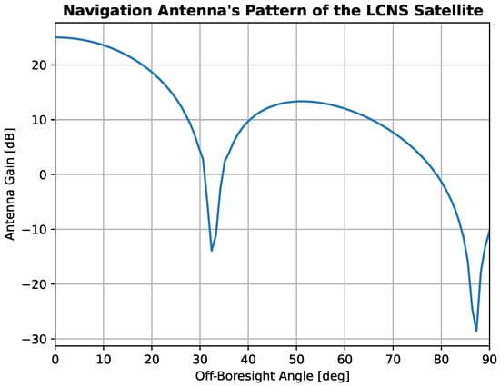
Figure 1.
LCNS navigation antenna pattern.
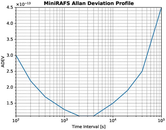
Figure 2.
MiniRAFS Allan Deviation profile. This curve was obtained on Earth in a laboratory environment, and therefore this technology is not flight-proven yet.
2.2. Lander
2.2.1. Lander Dynamic
The lander trajectory is based on an internal ESA study for the Argonaut lander []. Figure 3 shows the variation of altitude and velocity of the lander as function of time. This trajectory is visualised in Figure 4. The overall trajectory lasts for approximately 1 h and 30 min. The landing is initialised by a manoeuvre performed at the north pole to start the descent phase and a final touchdown on the South Pole.
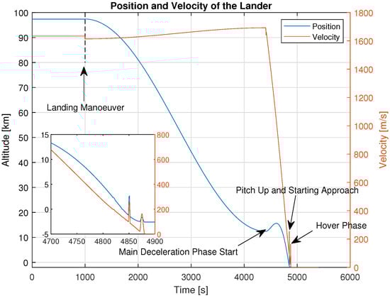
Figure 3.
Altitude of the lander.
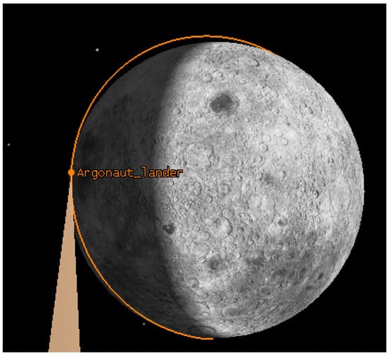
Figure 4.
Visualisation of the lander trajectory.
2.2.2. Lander Payload
The lander is assumed to be equipped with two antennas on both sides of the lander inclined by 45 degrees, with respect to the upward direction of the lander, to maximise the visibility of the Moonlight navigation signals during the last descent stage. Those antennas are connected to a Moon navigation receiver, which is based on the model of a space-borne GNSS receiver adapted to receive S-band signals and is designed to acquire and track the navigation message (containing, among others, orbit and clock data). The antenna pattern of the receiver assumed is presented in Figure 5 (note that it accounts for two patch antennas mounted in the configuration as shown in Figure 6 along the z-axis of the body frame).
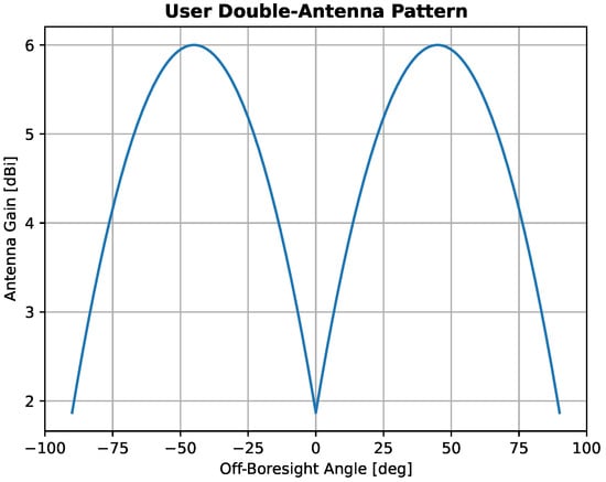
Figure 5.
Lander antenna pattern configuration.
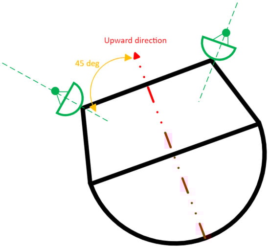
Figure 6.
Lander configuration diagram.
The user clock is simulated assuming the characteristics of a space-qualified OCXO (Oven-Controlled Chrystal Oscillator) for timing purposes. The Allan variance is shown in Table 3 and is representative of an OCXO used for that type of application [].
Table 3.
Characteristics of the OCXO used for the simulation.
3. Simulation
3.1. Software Architecture
Figure 7 presents the overall software architecture used for this contribution. At first the simulated trajectory of the LCNS constellation and the user trajectory are propagated. For this step, the ESA Godot software [] was used. The propagated LCNS orbits are then used as inputs to the Orbit Determination and Time Synchronisation (ODTS) software (cf. Section 3.2), generating the simulated navigation message, composed of satellites’ position, velocity and clock errors as well as uncertainty, which will be used later in the navigation filter. The lander and LCNS trajectories are then used in ESA’s LuNavSim simulator to generate the simulated measurements (pseudoranges and Doppler) and link information (visibility, C/N0, etc.). The user trajectory is also used within the IMU simulator to produce the IMU measurement time series. These measurements are then passed to the navigation filter that performs the PVT estimation of the lander.
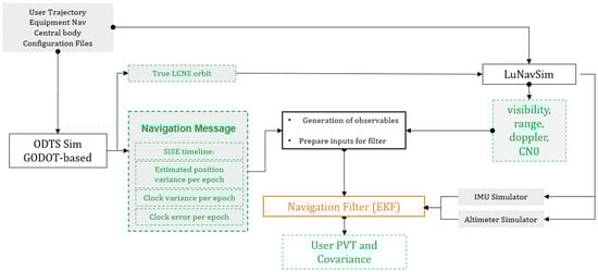
Figure 7.
The software architecture. The IMU simulator is not integrated into the results for the current contribution.
3.2. Orbit Determination and Time Synchronisation
The purpose of the ODTS simulation is to obtain a time series of the Signal-In-Space Error and the Signal-In-Space Accuracy for each satellite of the LCNS constellation. As such, the process is composed of two distinct steps. First, a simulation step is performed to propagate the orbit of the satellite, relying on a precise dynamical model, after which an observation model is used to model the measurements (note that these are range and Doppler measurements between the LCNS satellite and ground station using the K-band TT&C link). In the second step, the position, velocity and clock of the LCNS satellite are estimated using a batch least-square estimator.
The architecture of the ground segment used to perform these operations assumes a network of small dish antennas (diameter 26m) providing a two-way coherent K-band link using a Spread Spectrum (SS) modulation. The ground segment uses the Multiple Spacecraft Per Aperture (MSPA) technique, which, combined with the SS modulation, allows the implementation of Single-Beam Interferometry (SBI) to improve the performances []. The ground segment assumes three small antenna dishes are considered in the following locations: Cebreros (Spain), New Norcia (Australia) and Malargüe (Argentina).
The ODTS simulation relies on ESA’s Godot software [] for the propagation of the LCNS orbits. To account for inaccuracies of the dynamical model due to missing or mismodelled accelerations compared to a real environment, a perturbed dynamical model is used in the estimation process []. In particular, the dynamical model of the spacecraft in the propagation of the LCNS orbit accounts for
- The gravitational mono-pole accelerations associated with the Earth, the Moon and the Solar System planets;
- The spherical harmonics of the Moon, up to degree and order 120;
- The spherical harmonics of the Earth, up to degree 2;
- The non-gravitational acceleration due to the solar radiation pressure (SRP) acting on the satellites.
To model the SRP, the spacecraft is modeled as a box-wing (similar to the Galileo satellites) with one plate for the solar panels (area of 1.5 m2), one plate for the satellite’s antenna (area of 0.10 m2) and a sphere (radius of 0.34 m) for the satellite’s platform. The mass of the spacecraft is set to 230 kg.
The ODTS simulator relies on the following observables: Two-Way Doppler, Two-Way Ranging and SBI (providing the angle between two satellites as seen from the ground) measurements for estimation purposes. Both the observation model and the Time Synchronisation (TS) strategy are defined in []. The TS strategy relies on the time-tagging of the two-way measurements by the satellite considering three epochs:
- t1: epoch of the signal of transmission from ground.
- t2: epoch of the signal of reception onboard.
- t3: epoch of the signal reception on ground.
The LCNS satellite will then add its time t2 in the signal sent back to Earth. The desynchronisation error can thus be computed as shown in Equation (1) [].
where represents the one-way return link travel time. The desynchronisation accuracy is driven by both OD performances along the line-of-sight (LOS) and by the precision of the timestamp operations (the measurement of and ). Since the time-tag precision can be bounded to the sub ns level, the TS accuracy is mainly driven by the OD error mapped onto the line-of-sight. These onboard clock time series can be used to fit to a second-degree polynomial to yield the clock prediction parameters (i.e., the parameters to be used in the navigation message).
This leads to the computation of the SISE (Signal-in-Space Error) for position and velocity as shown in Equations (2) and (3).
where represent the true satellite position, velocity, clock bias and clock drift, respectively, whereas the bar symbolises the broadcast coordinates and the satellite-predicted clock bias and drift. Equations (2) and (3) are provided by the ODTS simulator as well as the associated uncertainty from the estimation process (equivalent to the Signal-in-Space Accuracy—SISA).
3.3. Navigation Filter
3.3.1. Extended Kalman Filter
The navigation filter implements an Extended Kalman Filter (EKF), which estimates the position, velocity and clock parameters of the lander. The used filter for this analysis is presented in []. The noise model for the observables is derived from the DLL and FLL equations derived by Kaplan and Hegarty []. The only difference is in the process noise used in the EKF. Here, an adaptive process noise is used based on the estimated velocity of the lander by the filter. The slower the lander, the smaller the value of the process noise used in the EKF.
For the initialisation of the EKF navigation filter, a single epoch weighted least squares (WLS) algorithm provides an initial solution and covariance of the lander PVT. To initialise the WLS, the position of the lander is supposed to be known at kilometer level (for instance, through direct-to-Earth tracking), which is a conservative approach compared to previous work [].
3.3.2. Altimeter
In this contribution, an altimeter is also used to provide an additional (height) measurement to the navigation algorithm to estimate the PVT solution with better accuracy (and to have a metric relative to the surface). The altimeter is estimated as additional range information between the surface of the lunar geoid and the user. The position of the lander can be expressed as the sum of its altitude ( provided by the altimeter) and the selenoid’s radius R (cf. Equation (4)).
Thus, the measurement model is updated as such ( is defined in []):
The covariance model is defined as per Equation (6), where is the combined uncertainty of the altimeter and terrain mismodelling measurements are considered as white noise with a variance of 5 metres. and are the covariance on the pseudorange and range-rate measurement as defined in [].
4. Results
This section will focus on the 3D error as computed in Equation 7, where denotes the position component estimated by the receiver. Both simulations are using the adaptive process noise explained in Section 3.3.1.
4.1. Precision Landing with LCNS
The first simulation performed for this contribution is the ODTS simulation based on the methodology explained in Section 3.2. The assumed refresh rate for the navigation message is 2 h (i.e., the clock and orbit are propagated for 2 h and fitted to a navigation message). The SISA (Signal In-Space Accuracy) value, for the position, velocity and satellite’s clock, used in the navigation filter is the maximum computed by the ODTS filter over the 2-h validity period. A one-day time series of the SISA values is available in []. Table 4 reports the maximum value of the SISA for position, velocity and clock for the studied lander case. Figure 8 shows the visibility of the LCNS constellation as seen by the user in comparison to the altitude. The LCNS constellation was optimised to have maximum visibility during the last descent phase, which is the most critical for landing operations.
Table 4.
The maximum SISA value for the simulated LCNS constellation.
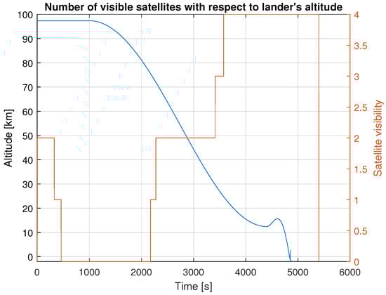
Figure 8.
Number of visible satellites in comparison to lander’s altitude.
Figure 9 shows the 3D position error between the lander’s true position and the estimated position by the navigation filter. The figure only shows the position error when four satellites are visible. Table 5 presents the mean, 95th and 99th percentile of the 3D position error. The error is below 50 metres 99 percent of the time. This is in line with the recommendation of the ISECG, which defined the landing accuracy to be below 90 m to enable safe landing and lunar operations. Around 4400 s and 4850 s, two peaks are visible in the error time-series plot. These events coincide with the last two manoeuvres shown in Figure 3. During these events, the engine of the lander is activated to slow down the lander. As the propagation model assumes a constant velocity propagation from one epoch to the other, this sudden change implies a propagation error in the filter for a few epochs, after which the filter converges again. In a real system, these events are scheduled based on the lander’s altitude. As the lander has a good estimation of its position during the descent, it is possible to predict this behaviour in advance and thus adapt the filter during those manoeuvres (i.e., modifying the process noise). Another option to be more robust against such events is using a tightly coupled navigation filter (exploiting an intertial measurement unit).
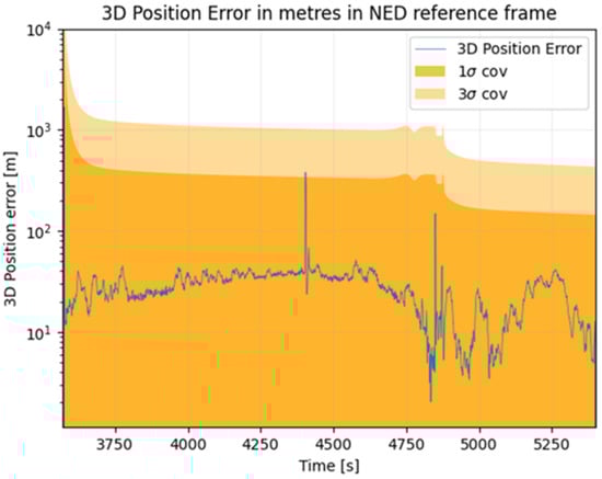
Figure 9.
Three-dimensional position error assuming GNSS-only positioning.
Table 5.
Three-dimensional position error for GNSS positioning.
4.2. Precision Landing with LCNS Aided by an Altimeter
Figure 9 shows the 3D position error between the true position of the lander and the position estimated by the navigation filter assuming an altimeter that provides height measurements. Table 5 presents the mean, 95th and 98th percentiles of the 3D position error for this second case study. Results presented here are in line with the previous covariance analysis in [], showing a mean error of 17 m using five satellites. The accuracy achieved in this paper with four satellites and the altimeter, assuming simulated measurements, is comparable to their covariance analysis. The addition of the altimeter also allows for a reduction in the mean position error by a factor of 2 during the descent phase as shown in Figure 10 and Table 6. Nevertheless, the 99th percentile position accuracy still has the same order of magnitude. To improve the latter, a more complex architecture leveraging additional sensors (i.e., IMU, visual navigation, etc.) must be analysed in future work.
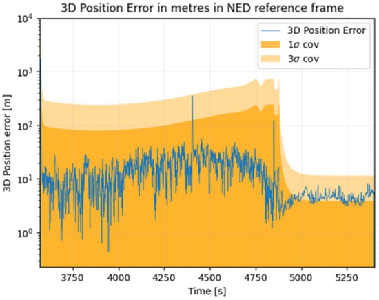
Figure 10.
Three-dimensional position error assuming GNSS positioning of the lander is aided by an altimeter.
Table 6.
Three-dimensional position error for GNSS and altimeter positioning.
5. Conclusions
According to the assessment performed by the ISECG and reported in the Global Space Exploration Roadmap [], one of the key identified challenges of future lunar exploration is the navigation accuracy of future landers. Even though Earth-GNSS can be used above MEO, on Earth-to-Moon transfer orbits and up to lunar orbits [], it cannot provide sufficient performances in this context to ensure a safe landing. The proposed LCNS constellation aims to solve this problem by providing, in lunar orbit, navigation capabilities to enable real-time positioning, velocity and timing (PVT) for different orbital, landing and surface users.
The goal of this paper was to further extend the previous variance–covariance analysis performed by [], by adding a real state estimation module and using more representative ODTS performances. To improve the performance of a lander navigation engine using an LCNS, an altimeter was implemented as an external sensor.
The simulation showed that the achievable positioning performances when using four satellites and the altimeter is around 40 metres in real time with a 99% percentile error, which is in line with previous works and matching the requirement of the ISECG. However, this error grows during manoeuvres before converging. As a recommendation for future work, to improve the result and have a better prediction, a tight IMU coupling should be studied as it will be likely part of the navigation suite of a lunar lander.
In conclusion, it is shown that a simple lunar-orbit GNSS-like constellation, such as the one planned as part of the ESA Moonlight program, combined with an altimeter, is sufficient to provide the level of accuracy needed for future lunar surface exploration, which shows the enormous potential of such technology.
Author Contributions
Conceptualisation, Y.A., F.T.M., R.D.S., D.V.P. and J.V.-T.; methodology, Y.A. and F.T.M.; software, Y.A.; validation, Y.A., F.T.M. and R.D.S.; writing—original draft preparation, Y.A.; writing—review and editing, Y.A. and F.T.M. All authors have read and agreed to the published version of the manuscript.
Funding
This research received no external funding.
Institutional Review Board Statement
Not applicable.
Informed Consent Statement
Not applicable.
Data Availability Statement
The data presented in this study are available upon request from the corresponding author.
Conflicts of Interest
The authors are all employed by the European Space Agency and declare no conflicts of interest.
Abbreviations
The following abbreviations are used in this manuscript:
| BPSK | Binary Phase Shift Key |
| EKF | Extended Kalman Filter |
| ELFO | elliptical lunar frozen orbit |
| ESA | European Space Agency |
| GNSS | Global Navigation Satellite System |
| IMU | Inertial Measurement Unit |
| ISECG | International Space Exploration Coordination Group |
| LCNS | lunar communication and navigation system |
| MSPA | Multiple Spacecraft Per Aperture |
| OCXO | Oven-Controlled Chrystal Oscillator |
| ODTS | Orbit Determination and Time Synchronisation |
| RAAN | right ascension of the ascending node |
| SBI | Single-Beam Interferometry |
| SISA | Signal-In-Space Accuracy |
| SISE | Signal-In-Space Error |
| SRP | solar radiation pressure |
References
- Artemis II Science Definition Team Report, NASA, Washington D.C., USA. 2020. Available online: https://www.nasa.gov/sites/default/files/atoms/files/artemis-iii-science-definition-report-12042020c.pdf (accessed on 25 August 2025).
- Global Governmental Space Exploration Investments to Reach $31B by 2031 as Public and Private Players Reach for the Moon; Euroconsult: Paris, France, 2022.
- Murata, M.; Kawano, I.; Kogure, S. Lunar Navigation Satellite System and Positioning Accuracy Evaluation. In Proceedings of the International Technical Meeting of The Institute of Navigation, ITM, Long Beach, CA, USA, 27–30 January 2022; pp. 582–586. [Google Scholar]
- Moonlight Programme, European Space Agency: Paris, France. 2022. Available online: https://esamultimedia.esa.int/docs/telecom/22.09.26_Moonlight_White_Paper.pdf (accessed on 25 August 2025).
- Draft LunaNet Interoperability Specifications; Technical report; NASA: Washington, DC, USA, 2022. Available online: https://esc.gsfc.nasa.gov/static-files/Draft%20LunaNet%20Interoperability%20Specification%20Final.pdf (accessed on 21 June 2022).
- LunaNet: Empowering Artemis with Communications and Navigation Interoperability; NASA: Washington, DC, USA, 2021. Available online: https://www.nasa.gov/feature/goddard/2021/lunanet-empowering-artemis-with-communications-and-navigation-interoperability (accessed on 25 August 2025).
- Takahashi, N.; Lee, M.; Grush, L. Japan Spacecraft Believed to Have Crashed on Moon During Landing; Bloomberg: New York, NY, USA, 2023. [Google Scholar]
- Communication and Positioning, Navigation, and Timing Frequency Allocations and Sharing in the Lunar Region (32-2R6), Space Frequency Coordination Group. 2022. Available online: https://www.nasalsmp.org/SitePages/Recommended-Frequency-Bands.aspx (accessed on 25 August 2025).
- Schier, J.; Sham, C.; Lee, D.; Abhyankar, K.; Clothier, K. International coordination and cooperation on LunaNet spectrum. In Proceedings of the 29th Ka and Broadband Communications Conference, Seattle, WA, USA,, 24–27 September 2024. [Google Scholar]
- SAFRAN Electronics and Defense MINIRAFS RB Atomic Frequency Standard, Paris, France. 2021. Available online: https://safran-navigation-timing.com/product/minirafs-rb-atomic-frequency-standard/?model_interest__c=MiniRAFS&product_interest___single_select=Atomic+Clocks+and+Oscillators (accessed on 25 August 2025).
- De Marchi, F.; Plumaris, M.; Burt, A.E.; Iess, L. A quick algorithm to compute an approximated power spectral density from an arbitrary Allan Deviation. arXiv 2023, arXiv:2311.00598. [Google Scholar] [CrossRef]
- ESA. What Is Argonaut; European Space Agency: Paris, France, 2024; Available online: https://www.esa.int/ESA_Multimedia/Images/2020/10/What_is_Argonaut (accessed on 2 May 2023).
- AXTAL GmbH. AXIOM70SL: Ultra-Low Phase Noise 10 MHz OCXO with HCMOS Output for Space Application (Space COTS Version). 2022. Available online: https://www.axtal.com/cms/docs/doc124949.pdf (accessed on 14 June 2022).
- ESA. GODOT Documentation; European Space Agency: Paris, France, 2022; Available online: https://godot.io.esa.int (accessed on 26 June 2023).
- Gregnanin, M.; Bertotti, B.; Chersich, M.; Fermi, M.; Iess, L.; Simone, L.; Tortora, P.; Williams, J. Same beam interferometry as a tool for the investigation of the lunar interior. Planet. Space Sci. 2012, 74, 194–201. [Google Scholar] [CrossRef]
- Tapley, B.; Schutz, B.; Born, G. Statistical Orbit Determination; Elsevier: Amsterdam, The Netherlands; Academic Press: Cambridge, MA, USA, 2024. [Google Scholar]
- Di Benedetto, M.; Boscagli, G.; De Marchi, F.; Durante, D.; Santi, F.; Sesta, A.; Plumaris, M.; Fienga, A.; Linty, N.; Sośnica, K.; et al. An architecture for a lunar navigation system: Orbit determination and time synchronization. In Proceedings of the 8th International ESA Colloquium on Scientific and Fundamental Aspects of GNSS, Sofia, Bulgaria, 14–16 September 2022. [Google Scholar]
- Audet, Y.; Melman, F.; Molli, S.; Sesta, A.; Plumaris, M.; Psychas, D.; Swinden, R.; Giordano, P.; Ventura-Traveset, J. Positioning of a Lunar Surface Rover on the South Pole Using LCNS and DEMs. Adv. Space Res. 2024, Under Review. [Google Scholar] [CrossRef]
- Kaplan, E.D.; Hegarty C., J. Understanding GPS/GNSS Principles and Applications; GNSS Technology and Applications Series; Artech House: Boston, MA, USA, 2017. [Google Scholar]
- Molli, S.; Tartaglia, P.; Audet, Y.; Sesta, A.; Plumaris, M.; Melman, F.; Swinden, R.; Giordano, P.; Ventura-Traveset, J. Navigation performance of Low Lunar Orbit satellites using a Lunar Radio Navigation Satellite System. In Proceedings of the 36th International Technical Meeting of the Satellite Division of The Institute of Navigation (ION GNSS+ 2023), Denver, CO, USA, 11–15 September 2023. [Google Scholar] [CrossRef]
- Grenier, A.; Giordano, P.; Bucci, L.; Cropp, A.; Zoccarato, P.; Swinden, R.; Ventura-Traveset, J. Positioning and Velocity Performance Levels for a Lunar Lander using a Dedicated Lunar Communication and Navigation System. Navig. J. Inst. Navig. 2022, 69, navi.513. [Google Scholar] [CrossRef]
- ISECG. Global Exploration Roadmap Critical Technology Needs. Available online: https://www.globalspaceexploration.org/wp-content/uploads/2019/12/2019_GER_Technologies_Portfolio_ver.IR-2019.12.13.pdf (accessed on 13 June 2023).
- Parker, J.J.K.; Dovis, F.; Anderson, B.; Ansalone, L.; Ashman, B.; Bauer, F.H.; D’Amore, G.; Facchinetti, C.; Fantinato, S.; Impresario, G.; et al. The Lunar GNSS Receiver Experiment (LuGRE). In Proceedings of the International Technical Meeting of The Institute of Navigation, ITM, Institute of Navigation, Long Beach, CA, USA, 25–27 January 2022; pp. 420–437. [Google Scholar] [CrossRef]
Disclaimer/Publisher’s Note: The statements, opinions and data contained in all publications are solely those of the individual author(s) and contributor(s) and not of MDPI and/or the editor(s). MDPI and/or the editor(s) disclaim responsibility for any injury to people or property resulting from any ideas, methods, instructions or products referred to in the content. |
© 2025 by the authors. Licensee MDPI, Basel, Switzerland. This article is an open access article distributed under the terms and conditions of the Creative Commons Attribution (CC BY) license (https://creativecommons.org/licenses/by/4.0/).