1. Introduction
In the context of growing demand for sustainable technological solutions, electric drives play a central role in achieving environmental responsibility, energy efficiency, and economic viability [
1]. The choice of an appropriate drive system—both in industrial applications and everyday use—must align with these principles. Induction motors (IM) are among the most widely used types due to their reliability, low cost, ease of maintenance, and resilience under varying load conditions. The introduction of variable-frequency inverters for speed control has further increased their appeal, making them a viable alternative to traditional DC motors in systems such as conveyor belts, excavator rotors, and other automated machinery.
The efficiency of asynchronous and synchronous motors is 85–90% at high and medium voltage. At low voltage, typical for household drives, it reaches 95%. For comparison, the efficiency of internal combustion engines is 40%. It remains high at 90–98%, even when using rectifiers or batteries [
2]. One of its clear advantages is the lack of carbon emissions, which is among the main reasons for the mass penetration of electric machines [
3]. It consumes one-third of the electrical energy produced. Its use is recommended by the European Union and new laws are constantly being issued to this end [
4].
In addition, through IoT systems, the parameters of these engines can be successfully monitored and controlled remotely. This is their significant advantage over internal combustion engines. In addition, through simulation models, they can be studied to increase their efficiency [
5,
6].
These characteristics mean that asynchronous motors are not only applicable in practice but also occupy a prime position in industry. In industrial settings, IMs are extensively utilized to power hoisting equipment, crushers, thickeners, mixers, pumping units, and more [
7,
8]. They are also increasingly applied in electric transportation—including electric cars, trains, and bicycles—due to their affordability and compatibility with modern control systems [
9]. The ability to control these motors remotely, including wirelessly and through frequency variation, enhances operational flexibility while reducing energy consumption [
10,
11]. For instance, the use of variable-frequency drives (VFDs) can achieve up to 50% energy savings, while direct torque control (DTC) methods can lead to around 30% improvement [
12].
Analyzing industry applications and electric drives, it is necessary to mention world leaders such as Sandvik LH409E, which implement electric machines in underground and open-pit mines [
13]. It is known that their loaders and mining combinations operate successfully 24 h a day under remote control without a driver. This advantage is inevitably a result of the possibilities offered by asynchronous motors, which are controlled by an inverter. High efficiency and safety are among the reasons for its successful implementation. High in the atmosphere, the air is thin and internal combustion engines cannot work optimally. Underground, especially in mines that are dangerous due to dust and gas, there is a real danger that internal combustion engines will explode. In this environment, DC machines cannot be used either, because the transfer of energy and their regulation through rheostats makes the process more expensive than asynchronous motors.
Permanent magnet (PM) motors are gaining popularity, with their usage reaching 96%, compared to 90% for standard motors. Despite this trend, induction motors maintain a strong presence in the industry due to their robustness and adaptability. The growing need for automation and wireless control is essential for improving operational efficiency, reducing costs, increasing sustainability, and, most importantly, ensuring process safety [
14,
15].
However, advanced control methods are not without their drawbacks. They often introduce side effects such as harmonic distortion and electromagnetic interference, which can negatively impact system performance. One particularly important issue is magnetic saturation in the motor’s iron core, which can distort the motor’s behavior and increase losses.
Over the years, numerous mathematical models have been proposed to analyze and simulate the behavior of induction motors. Some are simplified and suitable for basic analysis, while others are more advanced and account for dynamic and transient processes. Still, there is no single, comprehensive mathematical framework capable of describing all relevant phenomena occurring in induction motors under real-world operating conditions. There is a lack of a unified approach for accurate modeling and optimal design. Hence, it is still necessary to create and investigate such models.
A model based on the generalized electrical machine (GEM) theory has been proposed in [
16] and implemented in MATLAB/Simulink. This approach enables the analysis of dynamic and transient characteristics such as overshoot, oscillations, and peak values. However, the GEM-based model has several limitations, including:
An inability to account for iron core losses,
Phase shifts in the stator currents,
Magnetic saturation in the motor’s magnetic circuit.
Addressing these shortcomings requires the refinement of existing models or the development of new, more accurate mathematical descriptions.
In response to this need, the current study introduces an enhanced simulation model of an IM, developed in the MATLAB/Simulink environment. In this way, the magnetic saturation is explicitly incorporated in the iron core, resulting in a more realistic and reliable representation of the motor’s behavior under dynamic and loaded conditions. The aim is to provide engineers and researchers with a more robust tool for the analysis, control design, and optimization of induction motor-driven systems.
2. Materials and Methods
In this study, the systems of differential equations describing the electromechanical properties of induction motors are conveniently written relative to a d–q coordinate system rotating at the speed of the machine rotor:
In Equations (1) and (2), the following notations are used:
u1d and
u1q—projections of the vector of the stator voltage on
d and
q axes, respectively;
ψ1d and
ψ2d—projections of the vector of the flux linkage of the stator and the rotor windings, respectively, on axis d;
ψ1q and
ψ2q—projections of the vector of the flux linkage of the stator and the rotor windings, respectively, on axis
q;
i1d and
i1q—projections of the vector of the stator current on axes
d and
q, respectively;
f1 and
f1n—frequency and nominal frequency of the current in the electric supply, respectively;
f2—frequency of the current in the rotor;
ω and
ωn—angular velocity and nominal angular velocity of the field of the motor, respectively;
T1 and
T2—time constants of the stator and the rotor current loop for short-circuited winding;
Tm—electromechanical time constant of the motor;
n—rotational speed of the rotor;
mw—resistive torque reduced to the motor shaft; m—torque reduced to the motor shaft;
L11 and
L’22—inductance of phase of the stator and reduced inductance of phase of the rotor, respectively;
L12—mutual inductance;
Un and
In—nominal supply voltage and nominal current, respectively.
As a result of the saturation of the iron core, the inductive resistance of dissipation decreases. In this case, the dependence of the reactances of dissipation of the stator and rotor windings on the relevant currents is fundamentally important.
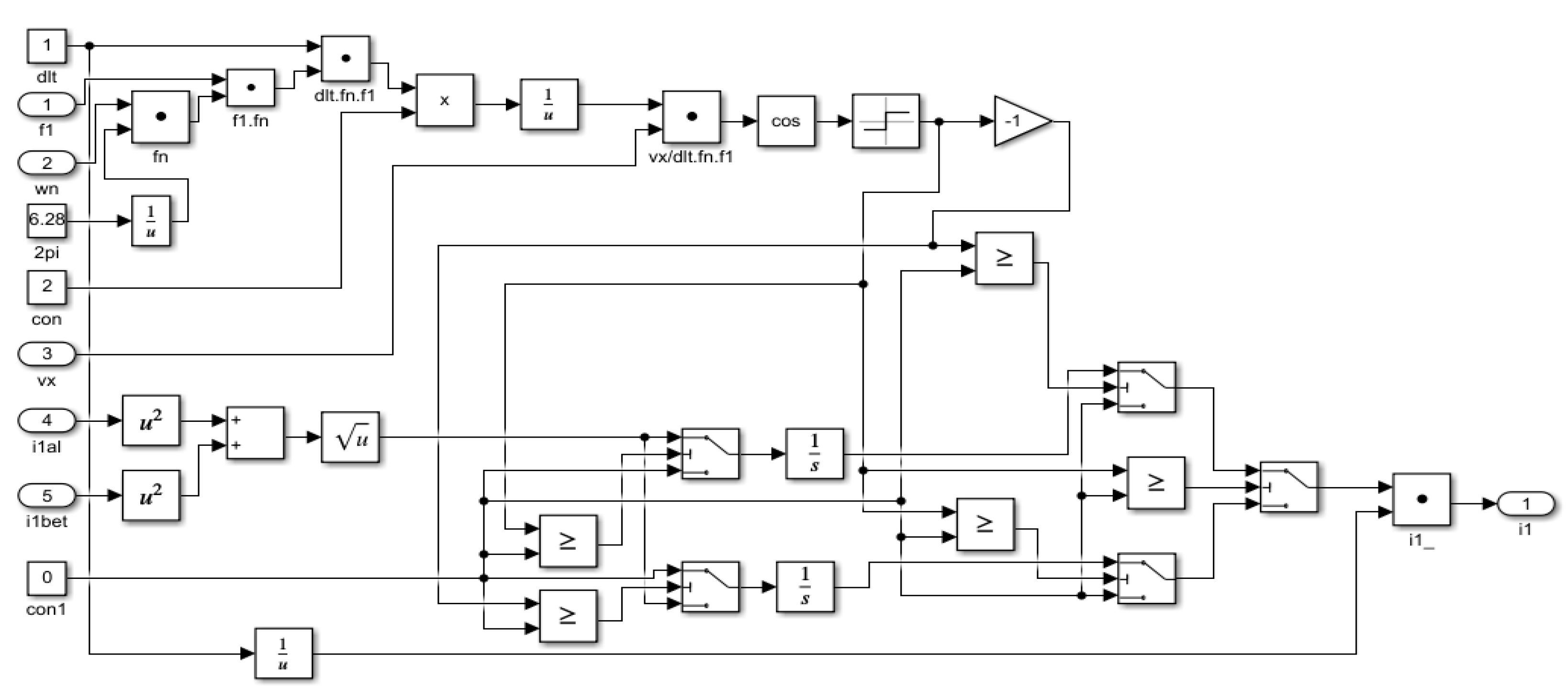
A simulation model for investigating dynamic characteristics of electrical drives with induction motors was developed in MATLAB/Simulink, 2015. This model takes into account the saturation in the iron core. The block diagram of the model when a symmetrical voltage supply is used is shown in
Figure 1. The created block diagram of the clarified simulation model of the induction motor is presented as a subsystem. This allows us to consider the saturation in the iron core.
The influence of the saturation in the simulation model is considered according to the change in the inductances L
11, L
12 and L
’22 (x
11, x
22 and x
12, respectively), the time constants T
1 and T
2, and the coefficient of dissipation σ as a function of the current i
1. The block diagram of
Invar of the simulation model is shown in
Figure 2.
It is evident that, when calculating the currents i1d and i1q, the values of the reactances of dissipation x1σn and x2σn (determined for i1 = i1n) must be determined. Moreover, they are dependent on current. Using the block diagram of the Invar invariance of the calculation upon the current, the reactance of dissipation is achieved.
The coefficient of dissipation σ, as a function of the current i
1, is calculated in
Raz, shown in
Figure 3; it is denoted as Subs9 in
Figure 1.
3. Results and Discussion
Using the developed accurate simulation model, which accounts for magnetic saturation through the variation of inductances, the influence of saturation on the dynamic characteristics of conventional induction motors was investigated.
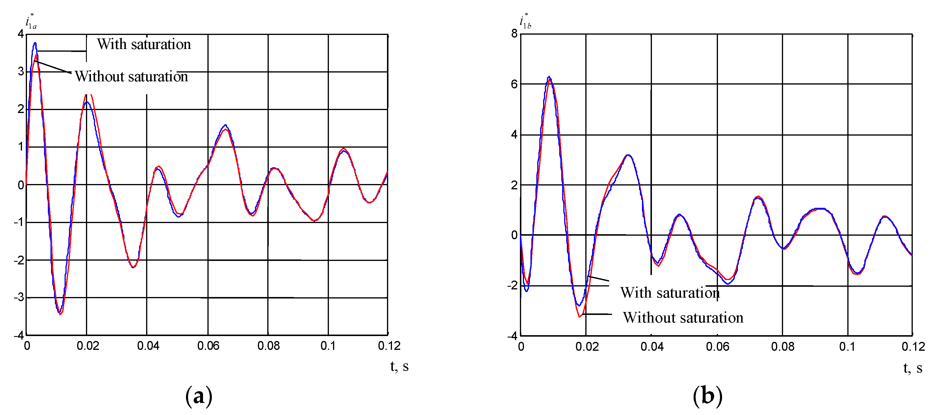
This study presents simulation results for induction motors of type MTF 211-6. In
Figure 4, the transient responses of the currents in the phases of the stator are shown—i*
1a = f(t) − 4a), i*
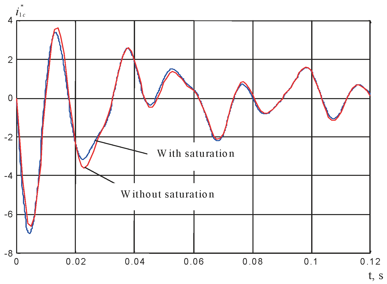
1b = f(t) − 4b). The transient responses of the currents in the phases of the stator i*
1c = f(t) are given in
Figure 5. All current values are expressed in relative units with respect to the nominal current i
1. Two cases are compared graphically—one considering magnetic saturation in the motor’s iron core, and one without it.
Figure 4a displays the evolution of phase current i
1a during motor startup. When saturation is considered, the current exhibits a higher initial peak and a prolonged oscillatory period before settling, highlighting the nonlinearity introduced by the magnetic core. In
Figure 4b, the transient response of i
1b shows a similar tendency.
The presence of saturation results in increased amplitude and a subtle shift in waveform shape, suggesting enhanced magnetic interaction and a more pronounced dynamic effect.
Figure 5 presents the third phase current, i
1c, which likewise displays stronger oscillations and more extreme negative peaks under saturation conditions. The differences between the two cases become especially evident in the early moments of motor startup.
These observations confirm that magnetic saturation significantly alters both the amplitude and the shape of the current waveforms in all three phases. Neglecting this phenomenon in modeling can lead to inaccurate predictions of peak currents and transient responses, which are essential for precise control, system protection, and thermal management. The enhanced model thus offers a more realistic framework for analyzing induction motor behavior in practical scenarios.
MATLAB simulations can be used for various other applications for the non-destructive testing of materials for engines and machines, the replacement of materials for manufacturing elements of induction motors, and others scenarios.
4. Conclusions
The introduction of electric transportation—including cars, trains, and bicycles—makes a significant contribution to environmental sustainability, cost efficiency, and overall competitiveness. These advantages would not be possible without the widespread use of induction motors.
The growing relevance of remotely and electronically controlled induction motors is indisputable. These machines are now present in nearly every area of modern life, offering benefits such as improved energy efficiency, operational safety, and reduced environmental impact. Achieving precise control over motor behavior requires accurate knowledge of the machine’s parameters. For this reason, this study focuses on analyzing the effects of magnetic saturation and the resulting variations in inductance within the motor’s iron core.
The main contributions of the study are as follows: it provides an accurate simulation model of induction motors, which was developed in the MATLAB/Simulink environment.
The proposed model enables the investigation of the dynamic characteristics and time-domain responses of induction motors, taking into account effects that are typically neglected in conventional models—specifically, magnetic saturation in the iron core.
The implementation of the simulation with MATLAB/Simulink will allow for further research on the problem; it can also be used for the study of other asynchronous motors to enable their effective control.


