Abstract
The IEC 61108-7 standard focuses on the minimum performance required by shipborne receivers using satellite-based augmentation system (SBAS) L1 signals to be compliant with the performance specified in IMO Resolution A.1046(27). Apart from the minimum performance requirements, the standard specifies the testing methods and a full set of scenarios with their pass/fail criteria. To verify the feasibility of the tests defined in the standard, a comprehensive test campaign was carried out in a joint effort by the European Satellite Services Provider (ESSP) and the European Commission’s Joint Research Centre (JRC) under the coordination of the European Union Agency for the Space Programme (EUSPA). This paper presents an assessment of the validity and appropriateness of the test scenarios and the minimum performance requirements specified in the IEC-61108-7 standard. To conduct the campaign, dedicated setups were designed and implemented at the JRC and ESSP laboratories, where live and simulated GPS+SBAS signals were used. For the analysis, all the test cases (TCs) described in the standard were implemented, and two commercial devices were tested. From the results, it emerged that all the TCs were properly designed and implemented, thereby confirming the feasibility of the tests defined in IEC 61108-7.
1. Introduction
In the maritime domain, precise navigation is a key enabler for different operations [1]. Several applications encompassing complex operations, such as search and rescue missions, monitoring the marine environment, route planning, collision avoidance, and navigating narrow channels and harbors, where precision is paramount, rely on global navigation satellite systems (GNSSs).
GNSS technology is fundamental for maritime use, and it is important to acknowledge the robust infrastructure it relies on. Satellite constellations, ground stations, augmentation systems, and onboard receivers work harmoniously to ensure that mariners around the globe have access to reliable and accurate positioning information. The usage of GNSS in the maritime domain is governed by a framework of international standards and regulations designed to ensure that the technology is used safely, reliably, and effectively. These standards are established and maintained by various maritime and standardization authorities, including the International Maritime Organization (IMO), the International Electrotechnical Commission (IEC), and the International Organization for Standardization (ISO). One of the key IMO standards is the performance standard for shipborne GNSS receiver equipment, detailed in Resolution A.1046(27) [2]. The IMO is responsible for the Safety of Life at Sea (SOLAS) Convention [3], which requires all passenger ships and most types of cargo ship to be equipped with GNSS equipment to aid in search and rescue operations and to improve overall maritime safety. Although the resolution was approved in 2011, it is important to note that the IMO periodically reviews and updates its standards and resolutions to reflect technological advancements and changing needs. However, the fundamental requirements outlined in A.1046(27) for accuracy, integrity, continuity, and availability are principles that remain relevant in the context of modern radio-navigation systems.
The IEC has a pivotal role in the standardization of maritime GNSS technology through its specifications for maritime navigation and radio-communication equipment and systems. The IEC 61108 series is composed of several parts, each covering specific aspects and functionalities of GNSS receivers, ensuring that they meet stringent criteria for use in navigational equipment on board ships of all sizes and classes. These standards address the needs of mariners for precision, reliability, and continuity of service, even under adverse conditions. IEC 61108-1 [4] focuses on GPS receiver equipment, setting the minimum performance standards and methods of testing for GPS-based navigation. IEC 61108-2 [5] (for GLONASS), IEC 61108-3 [6] (Galileo), IEC 61108-4 [7] (DGNSS), IEC 61108-5 [8] (BeiDou), and IEC 61108-6 [9] (IRNSS) introduce the different GNSSs for multi-constellation GNSS receivers for enhanced redundancy and precision.
Most commercial maritime GNSS receiver models are SBAS-compatible but exhibit differences in their performance since they are not certified according to any specific test standard. In [10], IALA (International Association of Marine Aids to Navigation and Lighthouse Authorities) provides a description of all the elements of SBAS relevant to maritime administration (direct reception of SBAS signal in space (SiS) on board the vessels). This includes the reference requirements, the user equipment, the description of the service, and the operational scheme. IEC 61180-7 [11] was published on 3 May 2024. Part 7 of the IEC 61108 standard focuses on the minimum performance required by shipborne receivers using SBAS L1 signals to be compliant with the performance specified within IMO Resolution A.1046(27). Apart from the minimum performance requirements, the standard specifies the testing methods and a full set of scenarios with their pass/fail criteria.
The European Satellite Services Provider (ESSP) provided support to the European Union Agency for the Space Programme (EUSPA) for the whole IEC 61108-7 [11] standardization process. During the development of the standard, a fundamental building block was a feasibility analysis of the tests defined in the standard. The objective of this assessment was not to certify the compliance of the devices but to assess the validity and consistency of the requirements set out in the standard. Such an assessment is needed to make sure that the implementation of the test scenarios and the assessment of the pass/fail criteria can be made by certification laboratories that choose to build test setups according to IEC 61108-7. For the assessment, a comprehensive test campaign was carried out in a joint effort by ESSP and the Joint Research Centre (JRC) under the coordination of EUSPA. During the testing campaign, the whole suite of tests described in [11] was executed. The paper presents the preliminary testing validation activities carried out, with a specific focus on the setup design and realization.
2. Setup Design and Realization
JRC and ESSP prepared a testbed specifically designed to assess the implementation of the test scenarios and the assessment of the pass/fail criteria defined in [11]. All the tests were carried out—a subset of the tests at the EU Testing and Demonstration Hub for the GNSS Programmes of the JRC, in Ispra (Italy) [12], and the rest at the ESSP premises in Torrejon (Spain). A schematic representation of the setup used at the JRC is shown in Figure 1. The main elements of the setup are the following:
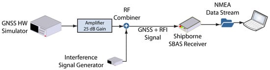
Figure 1.
Schematic representation of the experimental setup developed for the testing campaign of the IEC 61108-7 standard.
- The GNSS simulator on which the scenarios specified in the standard were implemented. For these tests, a commercial GNSS simulator able to generate GPS L1 C/A and EGNOS signals was used.
- An inline low-noise amplifier (LNA) with a 25 dB gain between the GNSS simulator and the SBAS receiver under test. This was employed to emulate the use of an active antenna, which is normally used in ships equipped with an SBAS receiver.
- Interference signal generator used to externally generate the interfering signals that are then combined with the GNSS signals. The instrument can generate four classes of waveform: continuous wave; frequency, phase, and amplitude modulations; calibrated additive white Gaussian noise; and arbitrary digital waveforms with an instantaneous bandwidth up to 100 MHz.
- A shipborne receiver or device under test (DUT) connected to the RF output of the LNA. This DUT outputs through one of its hardware interface NMEA messages or sentences according to the IEC 61162-1 standard [13]
- A data logger is used to collect the stream of NMEA messages from the hardware interface.
A fundamental element of the test setup realization is the calibration of the insertion losses of the radio-frequency combiner and of the cables. In the specific setup, insertion losses of about 4 dB were estimated; for the test, interference signal insertion losses need to be considered by increasing the power level of both the GNSS and the interference signals.
A test suite was developed on a host computer that managed the overall test execution in an automatic manner. First, it was able to interface with the DUTs via a virtual COM-USB RS232 and also over the network via a TCP socket. The control software was based on a Python software tool running on an Ubuntu OS laptop. This software was used to configure the receivers to send specific commands (e.g., a configuration sentence or a cold start command) to interface with the GNSS simulator to load and execute the test scenario. In addition, the application received and collected the NMEA sentences from the DUTs and those logged by the GNSS simulator.
The performance of the DUT was assessed by parsing and analyzing the logs of the NMEA messages output by the receiver during the tests and those from the GNSS simulator, which were taken as a reference to estimate the accuracy of the position velocity and timing (PVT) solution.
Throughout the exercise, all the test cases outlined in the standard were carried out. A detailed description of these test cases can be found in Section 6.10 of [11]; a brief overview of the tests and their corresponding pass/fail criteria is provided below. The performance of the receiver under static conditions is evaluated in TC-001 and TC-002. The key difference between the two scenarios is the oscillatory movement of the antenna in TC-002 to simulate the vessel’s roll movement due to waves. In addition, the accuracy of the position under dynamic conditions is assessed in TC-003 and TC-004. The pass/fail measure for these tests is based on a 95% acceptance rate for horizontal position error. The device’s capability to deliver an accurate position fix within the warm start time limit (i.e., 5 min) is examined in TC-005. TC 006 is designed to confirm the receiver’s ability to track the SBAS signal at varying power levels, while TC-007 verifies the receiver’s capacity to track and process SBAS PRN codes from 120 to 158. The receiver’s behavior in the presence of interference is scrutinized in TC-008 to TC-010, considering different types of interference, including pulsed, continuous wave, and wideband interference. In these cases, the receiver should consistently deliver accurate position results (95% horizontal error below 10 m) without failing to report a position in less than 5% of the time. Velocity information accuracy is assessed under different speed and course conditions in TC-011 to TC-013, with the pass/fail criteria based on a 95% acceptance rate for horizontal velocity error. The same TCs are used to evaluate the course error, with the pass/fail criterion again based on a 95% acceptance rate. TC-014 checks whether the receiver correctly provides the navigational and integrity status flag under three different signal and monitoring conditions. TC-015 aims to verify the receiver’s correct use of SBAS messages through a variety of different SBAS signal messages. Finally, TC-016 examines the correct switching between SBASs corresponding to the same (or different) SBAS service providers.
The following subsections describe in detail some example tests, for which the results are presented in Section 3.
2.1. Setup for TC-001: Static Accuracy Test
For this test, the standard allows the use of both simulated and live signals. For the testing campaign, live signals were used. The receiver under test was connected to a geodetic grade antenna located on the rooftop of an office building on the JRC Ispra site. The antenna was in open-sky conditions, and its position was carefully pre-surveyed. The coordinates were computed by post-processing after a long data collection; hence, an accurate position at the mm level was obtained, allowing the error assessment needed for the test. The pass–fail threshold for the test is based on the 95th percentile of horizontal errors; the test is considered successful if 95% of the error measurements are less than 10 m, as specified by the standard—a position measurement with a horizontal error of less than 10 m is marked as correct. To pass the test, at least 95% of the measurements must be marked as correct.
2.2. Setup for TC-002 and TC-003: Dynamic Accuracy Test
For these tests, simulated signals are used. For TC-002, an assessment of a dynamic scenario 25 min long was created. The scenario starts with a static phase of 12 min; then, the user starts moving with a constant acceleration till it reaches 48 knots; then, the user maintains a constant velocity, and after that, the velocity is reduced to zero within 5 s. Finally, the simulation is concluded with a static part. For TC-003, the same scenario is used, but a different speed is set. The user starts moving with a constant acceleration till it reaches 24 knots; the user maintains a constant velocity for 3 min, during which the DUT is subject to deviations of 2 m on either side of the straight line at a period of 12 s; finally, the velocity is reduced to zero. The pass–fail criterion in this case is also based on 95% horizontal errors. The reference position is provided by the simulator.
2.3. Setup for TC-008: Broadband Inteference
The aim of these tests is the assessment of the performance in terms of position accuracy and re-acquisition capability under broadband interference. For the test, simulated signals are used, a static scenario is used as baseline, and then, interference is added using an interference generator in charge of transmitting broadband interference with the following characteristics: a frequency of 1575.42 MHz, an interference bandwidth of 1 MHz, and total RMS power of −110.5 dBm. The interference generator is switched on/off according to the following schedule: 12:00:00–12:10:00 interference OFF; 12:10:00–12:50:00: interference ON; 12:50:00–13:00:00: interference OFF. In addition, the simulator is set up to disable the generation of GPS/SBAS signals for one minute every 10 min to verify that the receiver can acquire GPS/SBAS signals under interference conditions. The pass–fail criteria include 95% horizontal errors and solution availability—the receiver should not fail to report a position more than 5% of the time.
2.4. Setup for TC-011: Accuracy of SOG/COG (Constant Speed)
This test verifies the accuracy of speed and course over ground (SOG and COG) under different constant speed conditions, including 0.5 knots (A), 10 knots (B), and 20 knots (C). The SOG error threshold is 0.2 knots for cases A and B and 0.4 knots for case C. The COG error has to be lower than 3 degrees for case B and 1 degree for case C, and there is no check for case A due to the low speed of the vessel. For the test, simulated signals are used.
2.5. Setup for TC-016: SBAS Switch
The aim of this test is to check the correct switch between SBAS satellites providing corrections. This test is split into two sub-tests depending on whether the two SBAS satellites correspond with the same service provider ID or different ones. The DUT should be set up under simulated conditions, where two SBAS signals (different PRN codes), from the same or different service providers, are available and provide valid corrections. Then, after the nominal SBAS positioning solution is obtained by the DUT, the SBAS signal that is being used by the receiver is removed. The pass/fail criteria of this test include the verification of the solution mode to check that the SBAS mode is provided and the verification of the age of corrections to assure that the signals are not lost. Figure 2 shows the timeline used for a case where two different service provider IDs are tested.
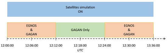
Figure 2.
Timeline of the SBAS activation for TC-016.
3. Sample Results
3.1. TC-001: Static Accuracy Test
This test evaluates the receiver accuracy in static conditions over a 24 h period. Figure 3 shows sample results using live GPS+EGNOS signals, including the SBAS correction age, the number of satellites, and horizontal/vertical errors. The standard requires a horizontal error lower than 10 m (95%), which is fulfilled in this test case. The number of satellites varies between 5 and 11, as shown in the upper left box. The geometry indicator (HDOP—horizontal dilution of precision) and the error time evolution are shown in the upper right box; the DOP values are always below 2, and the error is very stable, showing sub-meter performance.
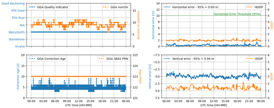
Figure 3.
Example results for the static accuracy test (TC-001).
3.2. TC-003: Dynamic Accuracy Test—A
The test aims to verify the receiver accuracy under dynamic conditions; the key elements of the test are shown in Figure 4. From the upper left box, it can be noted that the receiver switches to SBAS/DGPS mode about 6 min from the start of the scenario. The number of satellites varies between five and nine in the initial part of the test (from 12:00 to 12:07), while it remains constant at nine for the remaining part of the test. The horizontal and vertical error time evolution are shown in the right-hand boxes together with the relative geometric parameters. In these dynamic conditions, the receiver under test was able to provide sub-meter errors—the 95% horizontal error is 0.66 m.
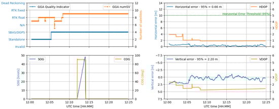
Figure 4.
Example results for dynamic accuracy test A (TC-002).
3.3. TC-004: Dynamic Accuracy Test—B
This test is similar to TC-003, with the difference being that the vessel is set to travel at 24 knots with varying travel directions (COG—course over ground). The receiver is expected to keep delivering nominal position accuracy under these conditions, as shown in Figure 5. The performance is very similar to that of the previous case for all the considered parameters; the number of tracked and used satellites is the same, and the horizontal errors are also very similar.
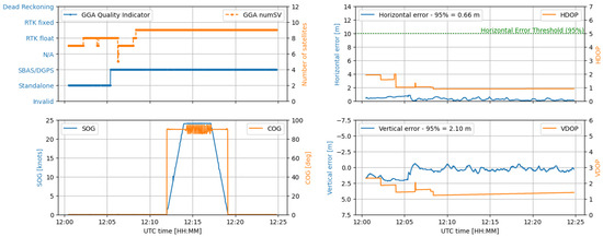
Figure 5.
Example results for dynamic accuracy test B (TC-003).
3.4. TC-008: Broadband Inteference
The test aims to verify the robustness of the receiver-to-broadband interference. As shown in the lower left box of Figure 6, there is a small decrease in C/N0 under interference, but the receiver is still able to re-acquire and deliver nominal position accuracy. The 95% horizontal and vertical errors are 3.16 m and 3.4 m, respectively. The receiver is able to re-acquire the satellites in the presence of interference, as shown in the lower left box.
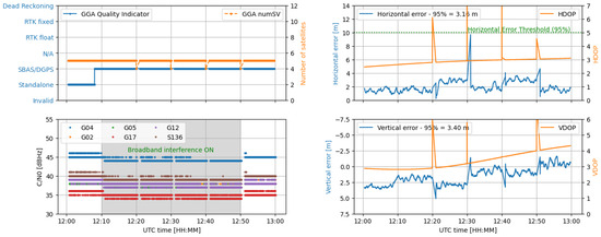
Figure 6.
Example results for the broadband interference test (TC-008).
3.5. TC-011: Accuracy of SOG/COG (Constant Speed)
TC-011 evaluates the performance of the receiver in terms of SOG and COG errors at three different speeds. The SOG and COG error time evolution is shown in the left part of Figure 7. The DUT fulfills these test criteria for the three cases.
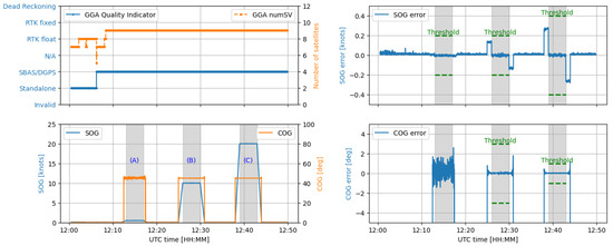
Figure 7.
Example results for the COG/SOG accuracy test (TC-011).
3.6. TC-016: SBAS Switch
The test aims to check the correct switch between SBASs corresponding to different service provider IDs. The test results are shown in Figure 8. The figure shows the periods in which EGNOS (PRN S126) and GAGAN (PRN S127) are enabled/disabled throughout the test. It can be observed that, when the EGNOS signal is switched off at 00:20, the receiver successfully switches to GAGAN and keeps providing an SBAS PVT throughout the test.
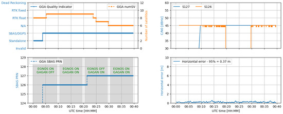
Figure 8.
Example results for the SBAS switch with different service provider IDs (TC-016).
4. Conclusions and Recommendations
In the framework of the new IEC-61108-7 standard, a comprehensive set of test cases was defined according to the specifications set out in the standard. These test cases were supplemented with actual test results from SBAS-enabled shipborne receivers, demonstrating how adherence to the requirements is assessed. This initiative aims to assist shipborne receiver manufacturers in adopting the IEC-61108-7 standard and help accredited test centers in developing the certification procedures for SBAS shipborne receivers. A broad test campaign was conducted by ESSP, JRC, and EUSPA to evaluate the IEC-61108-7 standard for shipborne receivers. The outcomes of this campaign confirmed the feasibility of the tests described in the standard. The definition and implementation of the test cases were found to be well designed and executed. Notably, the test results demonstrated that the receivers could provide sub-meter accuracy in both static and dynamic conditions, as well as maintaining their performance in the presence of broadband interference. The performance under various dynamic conditions, including changes in speed and course, fell within the accepted thresholds of accuracy.
In conclusion, the preliminary testing and validation activities have confirmed that the IEC-61108-7 standard offers a comprehensive and reliable framework for assessing the performance of shipborne SBAS receivers. Future work may focus on expanding the range of devices tested and supporting standardization activities for dual-frequency multi-constellation (DFMC) SBAS systems.
Author Contributions
Methodology, G.F., J.F., J.T., E.L. and C.G.; software, G.F., J.F., J.T. and C.G.; formal analysis, G.F., J.F., J.T., E.L. and C.G.; writing—original draft preparation, G.F., J.T. and C.G.; visualization, J.T.; supervision, E.C. and S.P.; project administration, E.C. and S.P. All authors have read and agreed to the published version of the manuscript.
Funding
This research was partially funded by EUSPA, grant number GSA/CD/09/19 SC1.
Institutional Review Board Statement
Not applicable.
Informed Consent Statement
Not applicable.
Data Availability Statement
The datasets presented in this article are not available because the receiver manufacturers involved in this study did not give written consent for their data to be shared publicly; therefore, due to the sensitive nature of the research, the supporting data are not available.
Conflicts of Interest
Authors Guillermo Fernandez and Elisabet Lacarra were employed by the company European Satellite Services Provider (ESSP). The remaining authors declare that the research was conducted in the absence of any commercial or financial relationships that could be construed as a potential conflict of interest.
References
- European Space Agency for the Space Programme. EUSPA EO and GNSS Market Report; Publications Office of the European Union: Luxembourg, 2024. [Google Scholar]
- International Maritime Organization. Resolution A.1046(27) Worldwide Radionavigation System; IMO: London, UK, 2011. [Google Scholar]
- International Maritime Organization. International Convention for the Safety of Life at Sea (SOLAS); IMO: London, UK, 1974. [Google Scholar]
- International Electrotechnical Commission. Maritime Navigation and Radiocommunication Equipment and Systems—Global Navigation Satellite Systems (GNSS)—Part 1: Global Positioning System (GPS)—Receiver Equipment—Performance Standards, Methods of Testing and Required Test Results; IEC: Geneva, Switzerland, 2003. [Google Scholar]
- International Electrotechnical Commission. Maritime Navigation and Radiocommunication Equipment and Systems—Global Navigation Satellite Systems (GNSS)—Part 2: Global Navigation Satellite System (GLONASS)—Receiver Equipment—Performance Standards, Methods of Testing and Required Test Results; IEC: Geneva, Switzerland, 1998. [Google Scholar]
- International Electrotechnical Commission. Maritime Navigation and Radiocommunication Equipment and Systems—Global Navigation Satellite Systems (GNSS)—Part 3: Galileo Receiver Equipment—Performance Standards, Methods of Testing and Required Test Results; IEC: Geneva, Switzerland, 2010. [Google Scholar]
- International Electrotechnical Commission. Maritime Navigation and Radiocommunication Equipment and Systems—GNSS—Part 4: Shipborne DGPS and DGLONASS Maritime Radio Beacon Receiver Equipment—Performance Standards, Methods of Testing and Required Test Results; IEC: Geneva, Switzerland, 2004. [Google Scholar]
- International Electrotechnical Commission. Maritime Navigation and Radiocommunication Equipment and Systems—Global Navigation Satellite Systems (GNSS)—Part 5: Beidou Satellite Navigation system (BDS)—Receiver Equipment—Performance Standards, Methods of Testing and Required Test Results; IEC: Geneva, Switzerland, 2020. [Google Scholar]
- International Electrotechnical Commission. Maritime Navigation and Radiocommunication Equipment and Systems—GNSS—Part 6: Indian Regional Navigation Satellite System (IRNSS)—Performance Standards, Methods of Testing and Required Test Results; IEC: Geneva, Switzerland, 2023. [Google Scholar]
- International Association of Marine Aids to Navigation and Lighthouse Authorities. IALA Guideline G1152 SBAS Maritime Service; IALA: Saint Germain en Laye, France, 2022. [Google Scholar]
- International Electrotechnical Commission. Maritime Navigation and Radiocommunication Equipment and Systems—GNSS—Part 7: Satellite Based Augmentation Systems—Performance Standards, Methods of Testing and Required Test Results; IEC: Geneva, Switzerland, 2024. [Google Scholar]
- Piccolo, A.; Cucchi, L.; Gioia, C.; Navarro, F.T.; Damy, S.; Motella, B.; Menzione, F.; Bonenberg, L.; Zoccarato, P.; Picchi, O.; et al. JRC Testing and Demonstration Hub for the GNSS Component of the EU Space Programme; Publications Office of the European Union: Luxembourg, 2024. [Google Scholar]
- International Electrotechnical Commission. Maritime Navigation and Radiocommunication Equipment and Systems—Digital Interfaces—Part 1: Single Talker and Multiple Listeners; IEC: Geneva, Switzerland, 2024. [Google Scholar]
Disclaimer/Publisher’s Note: The statements, opinions and data contained in all publications are solely those of the individual author(s) and contributor(s) and not of MDPI and/or the editor(s). MDPI and/or the editor(s) disclaim responsibility for any injury to people or property resulting from any ideas, methods, instructions or products referred to in the content. |
© 2025 by the authors. Licensee MDPI, Basel, Switzerland. This article is an open access article distributed under the terms and conditions of the Creative Commons Attribution (CC BY) license (https://creativecommons.org/licenses/by/4.0/).