1. Introduction
The principle of high pressure die casting (HPDC) is the injection of molten alloy into the cavity of a metal mould at high speed. The solidification of the melt is then carried out under high pressure. Under these conditions, it is possible to produce very complex castings with thin walls. Under certain conditions, the casting can be even less than 1 mm [
1,
2]. The mould is one of the most important parts of the whole process because it is here that the molten metal takes shape and the final product is created [
3]. The microstructure and mechanical properties of the castings are influenced by the thermal and kinetic conditions in the mould cavity. During die casting, many factors affect the casting process, such as the amount of heat in the melt, the injection velocity, the heat transfer from the melt to the mould, or the possible cooling of the mould [
4,
5]. Conventional moulds are made of blocks of metal, usually steel, using conventional machining techniques. Straight cooling channels are then drilled into the mould. This way, it is not possible to achieve sufficient proximity of the cooling channels to the mould cavity for the entire casting. This prolongs the cooling time and increases the production time per casting. A solution may be production of moulds with conformal cooling channels using additive manufacturing (AM) technology. With AM of metal powders, any shape can be created according to the requirements. Thanks to research into AM, the technology is becoming more advanced and efficient, and the use of conformal cooling channels reduces the occurrence of defects and increases the efficiency of the HPDC process. Compared to drilled cooling channels, up to 30% reduction in cooling time is achieved with AM moulds with conformal channels [
6,
7].
GD Druckguss is a manufacturer of zinc alloy castings. Currently, the potential for the operational implementation of mould-shaped parts produced by AM is being studied. The experimental shaped parts are made of AISI H11 steel, which is commonly used for moulds in the company. For the purpose of testing, an experimental mould-shaped part was designed and manufactured by conventional methods (hereafter the conventional part) and by additive manufacturing (hereafter the AM part) from the same grade of steel (AISI H11). Both shaped parts have been deployed to production outside of commercial projects and testing is taking place. Surface roughness measurements are used to assess wear. 3D scanning and a coordinate measuring machine are used to monitor dimensional stability. These measurements are applied to both the shaped parts and the castings themselves. In the present paper, the results of the measurements of the castings are summarized.
2. Materials and Methods
The experimental shaped part is designed with two cavities. The design includes the geometries that are most stressed during die casting and are subject to defects. The shaped parts and castings are shown in
Figure 1.
To evaluate the implementation of AM-shaped parts in the HPDC process, both shaped parts and castings from them were tested as new parts and then during service. Measurements were performed after every approximately 100,000 shots. Currently, the conventional part has been evaluated up to 520,000 shots. The AM part has been evaluated after 100,000 shots and is deployed for further wear investigations. As the shaped part has two cavities, it produces two castings designated as K3 and K4 each cycle. As mentioned, the shaped parts and castings are evaluated after each wear milestone is reached. Due to the limited scope of the paper, only the results of the casting K3 will be discussed below.
Three methods were used to evaluate the castings: 3D scanning using a ROMER Absolute Arm 7525SI laser scanner (Hexagon AB, Stockholm, Sweden) (hereafter 3D scanning), a coordinate measuring machine (Thome Präzision GmbH, Messel, Germany) (hereafter CMM), and a roughness measurement using a Mitutoyo Surftest SJ-410 Surface Roughness Tester (Mitutoyo, Kawasaki, Japan) (hereafter roughness tester).
With 3D scanning, the obtained point cloud was aligned using the method to the plane, axis, and centre point on the CAD model of the casting. The colour range of the dimensional deviations is +500 to −500 μm with a step size of 50 μm. This range is outside of the required dimensional tolerances of the castings. However, the method provides an overview of the general condition. Points were selected and subsequently measured using a CMM for comparison.
The CMM provides satisfactory accuracy (5 μm) at individual measurement points, but does not allow measurement of the entire object, so the points to be measured were selected for the castings. Alignment is performed using the same method as for 3D scanning, i.e., on the plane, axis, and centre point.
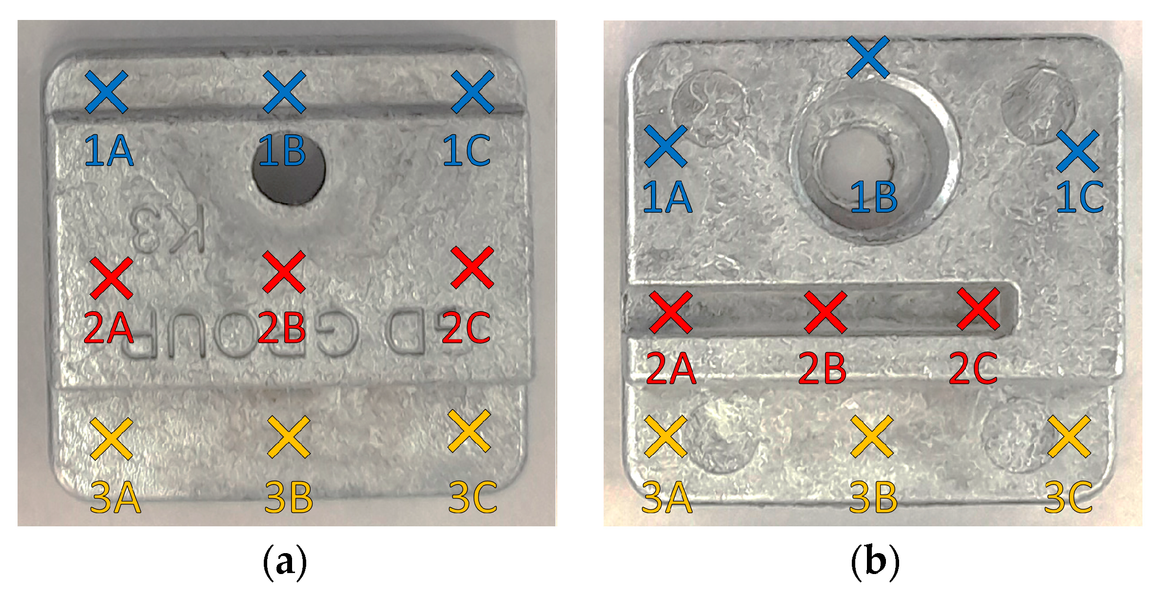
The roughness tester provides values to the thousandth of a μm. The measurement is performed on a section 80 μm long. Nine points on the top side and nine points on the bottom side of the casting were selected for measurement. Their positions and markings on the K3 casting are shown in
Figure 2.
The presented methods are the same as used in previous works by the authors to evaluate shaped parts [
8].
3. Results
An evaluation of a conventional part has been carried out on a new part and after 100, 200, 280, 400, and 520 thousand shots. The AM part was put into service later, so the evaluation has been carried out on the new part and after 100,000 shots so far.
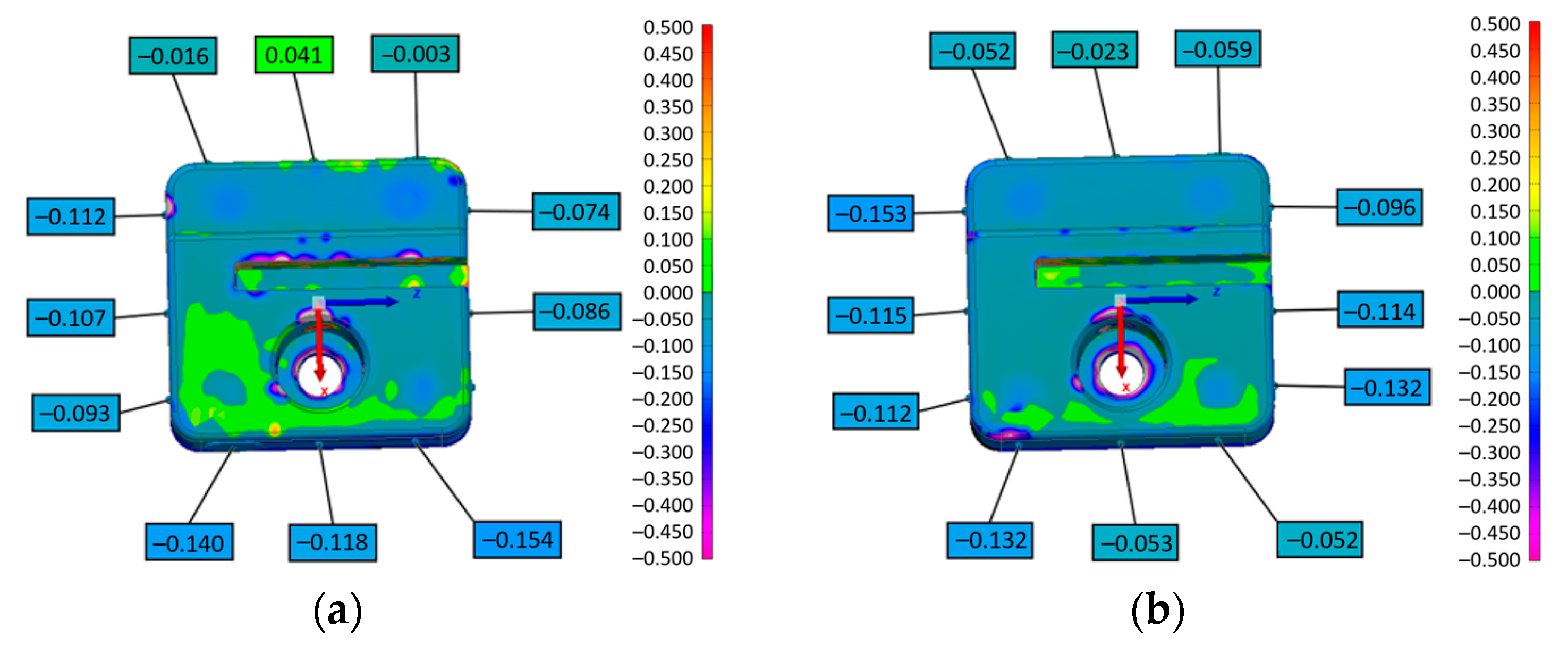
Figure 3 shows the results and comparison of 3D scanning and CMM for castings K3 from the new conventional part and after highest achieved wear, i.e., 520,000 shots.
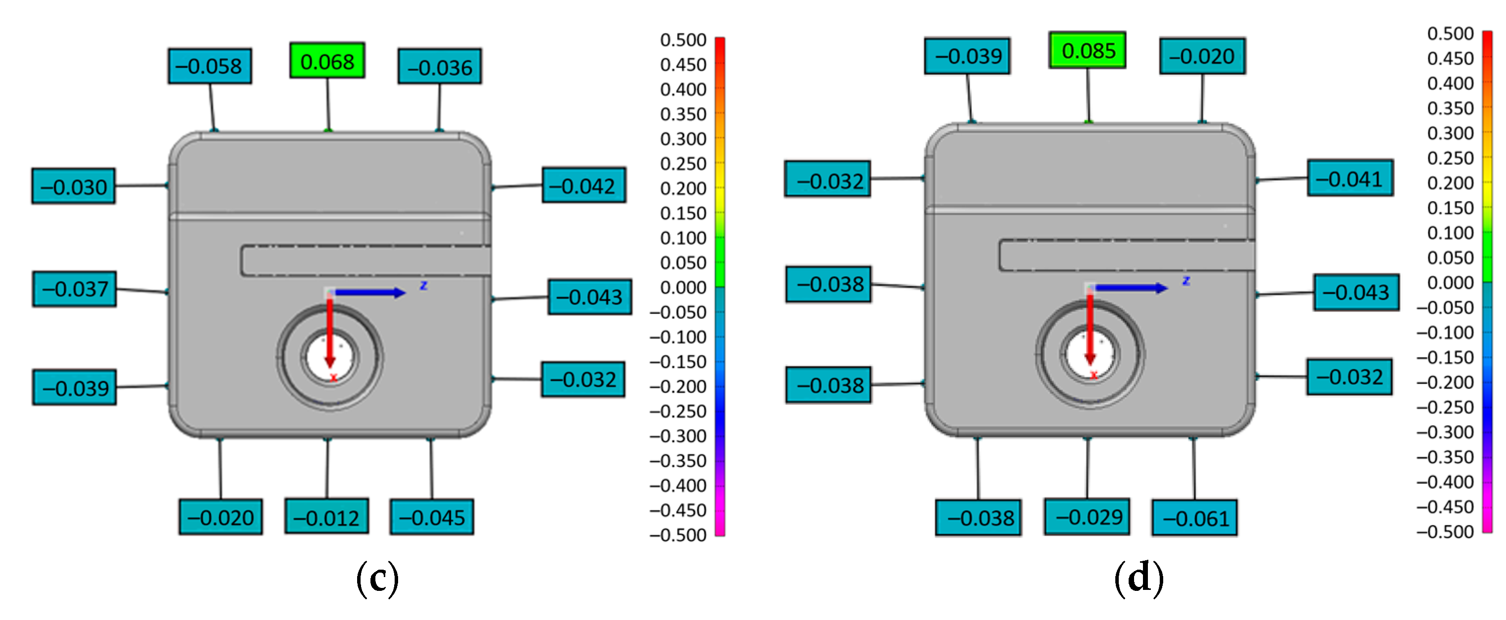
Figure 4 shows the results and comparison of 3D scanning and CMM for castings K3 from the new AM part and after highest achieved wear, i.e., 100,000 shots.
It is evident from the 3D scanning that the dimensional deviations are higher for castings from new shaped parts (
Figure 3a and
Figure 4a) than for parts that are in use (
Figure 3b and
Figure 4b). More accurate CMM measurements confirm this phenomenon. It can also be seen that castings from the AM part have larger dimensional deviations than those from the conventional part, both as new (
Figure 3c and
Figure 4c) and after use (
Figure 3d and
Figure 4d). A more detailed evaluation will be possible when the same wear rate has been achieved for both parts.
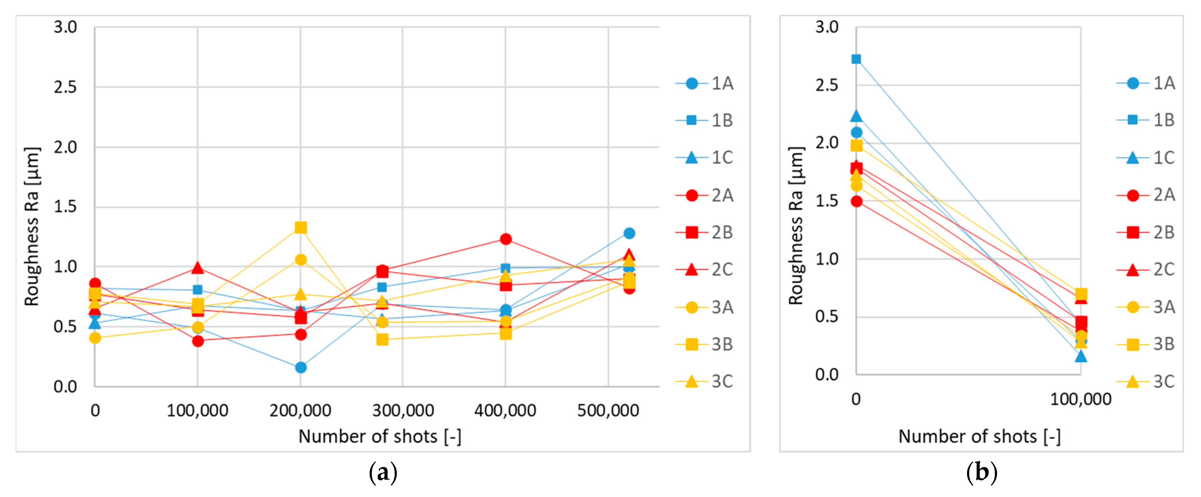
Figure 5 shows the changes of the roughness on the top side of the K3 castings during the use of the parts. The individual points correspond to the diagram in
Figure 2a.
The graphs in
Figure 5 show the changes in the roughness of the castings during the use of the shaped parts. The casting from the new conventional part show roughness below 1 μm. It noticeably changes both ways over the course of use. At the highest wear (520,000 shots), the roughness of the casting is in the region of 1 μm. For the castings from the AM part, the roughness from the new part is higher, but after 100,000 shots it drops to values below 1 μm at all measured points. This phenomenon was not observed in the castings from the conventional part. The changes in the roughness may be due to physical or physicochemical effects related to the increased temperature in contact with the zinc alloy, which partially smoothed the roughness of the part and thus the castings.
4. Conclusions
Measurements by three methods show that castings from the AM part are comparable to those from the conventional part in terms of dimensional stability and roughness
AM has potential in the production of parts for HPDC, allowing for geometries not achievable by conventional means
More thorough results will be available when higher and equal wear of shaped parts is reached
Further examination of the castings by computed tomography (CT) followed by metallographic examination is planned
Comparison with numerical simulations of casting and solidification is also possible
These methods would allow the internal structure of the castings to be investigated
Author Contributions
Conceptualization, K.G., L.S. and V.S.; methodology, K.G. and K.K.; formal analysis, K.K.; investigation, M.P., A.M. and V.S.; resources, R.K., J.T., A.M. and M.P.; data curation, K.K.; writing—original draft preparation, K.K.; writing—review and editing, K.K., K.G., L.S. and R.K.; visualization, K.K.; supervision, K.G., L.S. and R.K.; project administration, K.G. and R.K.; funding acquisition, K.G. and R.K. All authors have read and agreed to the published version of the manuscript.
Funding
The paper was prepared in the scope of the TREND programme, project FW03010323: research and development of shaped moulds from hardenable steels for casting zinc alloys in the application of modern technologies of additive production, heat treatment, surface treatment, and numerical simulations, supported from the resources of the Technology Agency of the Czech Republic.
Institutional Review Board Statement
Not applicable.
Informed Consent Statement
Not applicable.
Data Availability Statement
The raw data supporting the conclusions of this article will be made available by the authors on request.
Conflicts of Interest
Roman Kubeš, Václav Sochacký and Jaromír Trobl are affiliated with GD DRUCKGUSS s.r.o. The authors declare that this study received funding from Technology Agency of the Czech Republic. The funder was not involved in the study design, collection, analysis, interpretation of data, the writing of this article or the decision to submit it for publication.
References
- Roučka, J. Metalurgie Neželezných Slitin, 1st ed.; CERM: Brno, Czech Republic, 2004; pp. 101–103. [Google Scholar]
- Ferreira, J.C. A study of advanced die-casting technology integrating CAD/RP/FEA for Zn castings. Int. J. Adv. Manuf. Technol. 2006, 31, 235–243. [Google Scholar] [CrossRef]
- Pinto, H.A.; Silva, F.J.G.; Martinho, R.P.; Campilho, R.D.S.G.; Pinto, A.G. Improvement and validation of Zamak die casting moulds. Procedia Manuf. 2019, 38, 1547–1557. [Google Scholar] [CrossRef]
- Murray, M.T.; Griffiths, J.R. The design of feed systems for thin-walled zinc high-pressure die castings. Metall. Mater. Trans. B 1996, 27, 115–118. [Google Scholar] [CrossRef]
- Pinto, H.; Silva, F.J.G. Optimisation of Die Casting Process in Zamak Alloys. Procedia Manuf. 2017, 11, 517–525. [Google Scholar] [CrossRef]
- Karakoc, C.; Dizdar, K.C.; Dispinar, D. Investigation of effect of conformal cooling inserts in high-pressure die casting of AlSi9Cu3. Int. J. Adv. Manuf. Technol. 2022, 121, 7311–7323. [Google Scholar] [CrossRef]
- Jahan, S.A.; Wu, T.; Zhang, Y.; Zhang, J.; Tovar, A.; Elmounayri, H. Thermo-mechanical Design Optimization of Conformal Cooling Channels using Design of Experiments Approach. Procedia Manuf. 2017, 10, 898–911. [Google Scholar] [CrossRef]
- Koza, K.; Gryc, K.; Socha, L.; Pinta, M.; Kubeš, R.; Sochacký, V.; Mohamed, A.; Trobl, J. Introduction to the Methodology of the Study of Operational Wear of Experimental Shaped Parts of Moulds for HPDC of Zinc Alloys. In Proceedings of the 32nd International Conference on Metallurgy and Materials, Brno, Czech Republic, 17–19 May 2023. [Google Scholar] [CrossRef]
| Disclaimer/Publisher’s Note: The statements, opinions and data contained in all publications are solely those of the individual author(s) and contributor(s) and not of MDPI and/or the editor(s). MDPI and/or the editor(s) disclaim responsibility for any injury to people or property resulting from any ideas, methods, instructions or products referred to in the content. |
© 2024 by the authors. Licensee MDPI, Basel, Switzerland. This article is an open access article distributed under the terms and conditions of the Creative Commons Attribution (CC BY) license (https://creativecommons.org/licenses/by/4.0/).


 ,
, 