Abstract
This article analyses & describes a trapezoidal dual-band monopole antenna. The notch band monopole disables 4.4–5.7 GHz commercial communication equipment. The basic type operates at 2.5–4.4 GHz with a 500 MHz marginal bandwidth and 5.7–7 GHz with a 1000 MHz bandwidth. Present research optimises multiband trapezoidal antennas. Trapezoidal antennas improve multi-band wireless antennas. GSM, LTE, Wi-Fi, and 5G frequency bands start design. Inefficient and space-wasting, traditional antennas lack frequency range. Benefits of trapezoids: changing trapezoidal element sizes and angles enables the antenna to transmit many frequencies, sloping trapezium sides allow impedance changes without networks or tuning, numerical calculation and electromagnetic modelling optimise the trapezoidal antenna’s performance throughout the communication band, impedance matching, gain, and radiation efficiency provide transmission reliability, and broadband trapezoidal forms eliminate band-specific antennas & switches. Simplified antenna integration makes modern devices cheaper and simpler. In multiband applications, trapezoidal antennas outperform normal antennas. The antenna fits numerous wireless communication devices and systems due to its modest size and wide band coverage. The redesigned structure with notch increases operating band bandwidth and notches application bands between 4.4–5.7 GHz. By modifying trapezoidal geometry, we generate selective impedance transition notches to target crucial interference frequencies. Modern wireless communication systems with complicated interference situations can trust its careful engineering to provide good efficiency and radiation patterns across a wide frequency band while actively rejecting interfering signal. The peak realized gains obtained at 2.5 GHz is 2.4 dB, at 3.4 GHz it is 3.5 GHz and at 5.8 GHz it is 4.7 dB.
1. Introduction
There is a rising demand for microwave devices and antennas in various fields for their usage in the wide range of commercial communication applications, providing opportunities to engineers for the design of compact and novel models. The design specifications and parameters as per the future communication requirements need to be considered while developing such products. The demand for notch band antennas to restrict the operating band as per the specification is gaining its own advantage in communication fields. In the defence sector and in military communication especially, the demand for notch band antennas is to have more control on the spectrum.
The S-band rejection-based trapezoidal notch band antenna has been designed by Kaza [1]. The designed antenna model is blocking s-band and allowing L-band with ejection ratio of 36%. Ajay [2] produced a V-shaped metamaterial-based antenna with a flared element for notching 1.2–3.2 GHz and 4.2–4.8 GHz with a rejection ratio of 38% and 32%. Mohan [3] designed a wideband antenna which operates in the range of 3.1 to 8.4 GHz with notching from 5.6 to 5.9 GHz. Kosuru [4] developed a PIN diode-based notch band antenna with reconfigurable nature to block WLAN/IEEE-802 (WLAN-Wireless Local Area Network). In total, there are 11n bands in switching conditions. A split ring model-based structure has been used to design a metamaterial-based antenna by Venkateswara Rao [5]. The designed notch antenna structure is constituted on a conformal dielectric and the flexible characteristics are studied and found satisfactory in simulation and prototype measurement.
Rajia [6] deigned a reconfigurable antenna with a defected ground plane-DGP for the industrial, scientific & medical-ISM (International Safety Management) band. Vijaya [7] proposed a circular shaped monopole reconfigurability enabled antenna with the notch band characteristics. A transparent monopole for vehicular communication applications was designed by Sanjay [8] and a dual band notch monopole printed antenna was proposed by Rekha [9] for UWB-Ultra-wideband applications. Lakshmi [10] designed a tripartite cut reconfigurable monopole dependent model with a deserted base plane. Tilak [11] designed a heart shape monopole antenna with a planar artificial magnetic conductor-AMC support for high gain. Ramya [12] proposed a triple band notch type monopole antenna with a complimentary split ring resonator structure for improving directivity in the operating bands. Ibrahim [13] designed a fractal antenna for various wireless communication systems applications. Hua and Yan [14] designed a notch band antennas with reconfigurability and a C-slot. Few advanced models are designed by scientists with metamaterial structures and FSS- Food Safety and Standards [15,16,17].
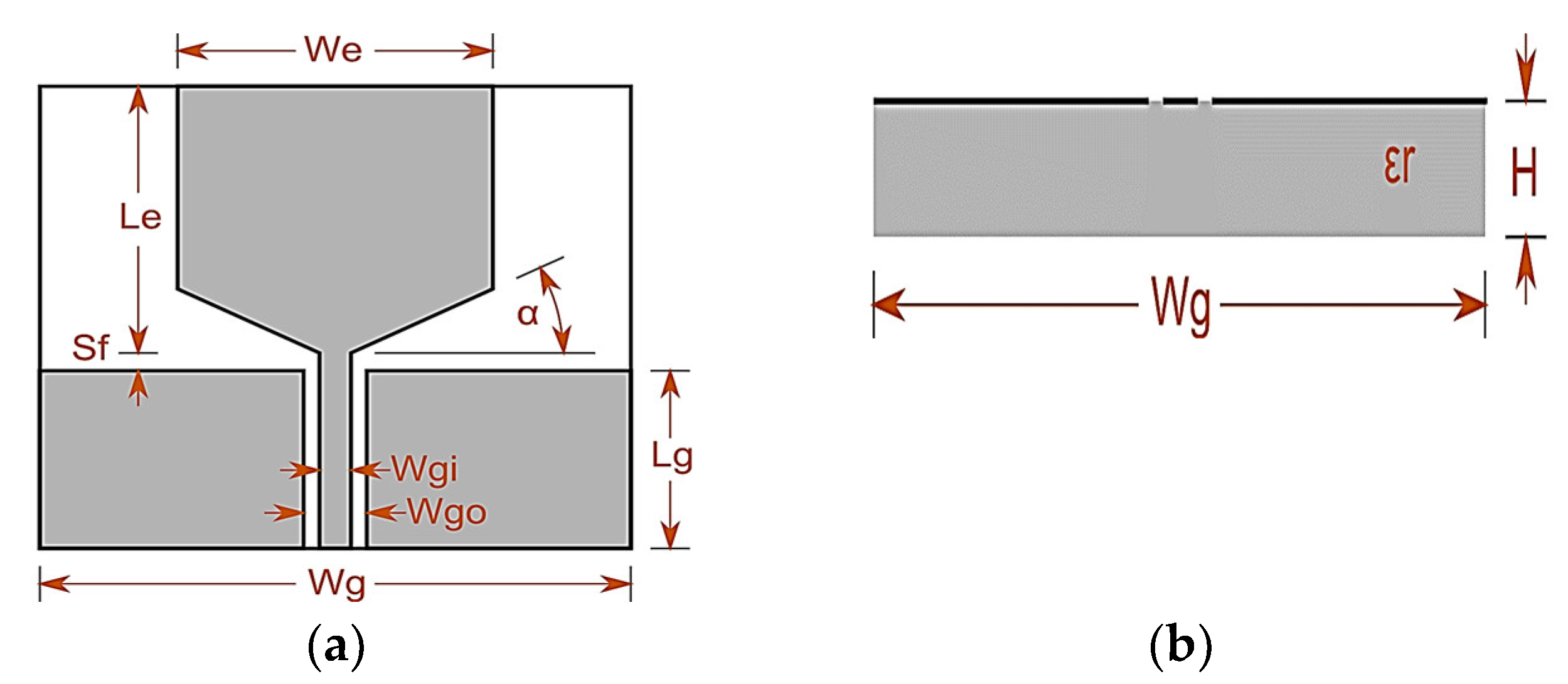
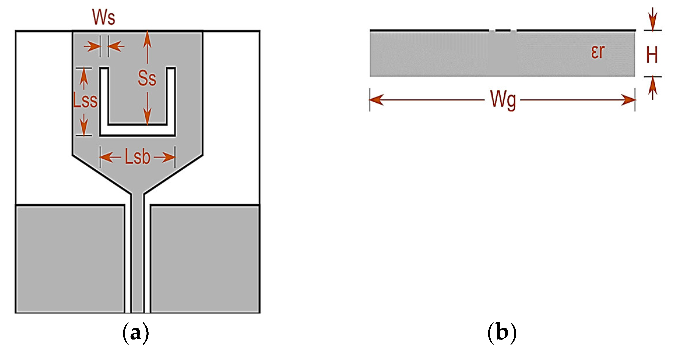
Antenna Modelling: A trapezoidal shaped monopole antenna is modelled into a notch band monopole with the placement of U-slot on the radiating structure [18]. Figure 1 projects the trapezoidal monopole and Figure 2 projects the notch band monopole. The dimensional view and side view of the trapezoidal monopole and the notch band monopole with coplanar waveguide feeding is presented [19]. The antenna is compact in dimensions and fabricated on the FR4 dielectric of thickness ‘h’ is 1.65 mm.
where λg is the guided wavelength. The coplanar waveguide feeding with 50-ohm impedance and ground gap with of 0.2 mm is used in this model. A U-shaped lot is placed in the radiating structure to attain the band notch parameter in the initial design [20]. The notch band antenna showing band rejection from 4.4–5.7 GHz and attained the bandwidth value of 1.3 GHz.
h > 0.06 λg
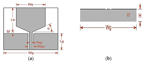
Figure 1.
Trapezoidal Monopole Structure Antenna, (a) Dimensional View, (b) Side View.
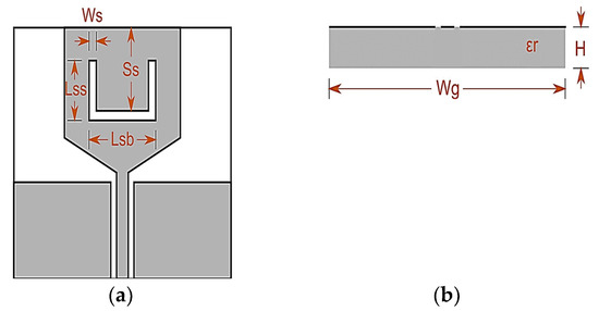
Figure 2.
Notch Band Trapezoidal Monopole Antenna, (a) Dimensional Look, (b) Side Look.
1.1. Benefits of Incorporating Notch Structure
The performance of an antenna and its ability to suppress interference in the 4.4–5.7 GHz band can be greatly improved by incorporating a notch structure. This is especially true in terms of bandwidth augmentation. Enhanced Bandwidth: a notch structure can reduce undesired frequencies in an antenna’s operational spectrum. This suppression allows the antenna to operate over a wider bandwidth, making it more versatile and adaptable to different communication needs. Adding a notch structure improves antenna gain, radiation pattern, and impedance matching [21]. The notch reduces resonances and standing waves, making the antenna more stable and efficient. Interference mitigation: multiple wireless communication systems coexist in the 4.4–5.7 GHz region, making interference difficult. The notch structure can target specific interfering frequencies to reduce interference and improve the antenna’s capacity to receive and transmit signals in noisy environments. Notch structures can dynamically target different interfering frequencies, allowing frequency reconfigurability. This versatility is crucial when the interference landscape changes or numerous frequency bands are needed.
1.2. The Antenna’s Frequency
The antenna’s broad frequency coverage, spanning 2.5–4.4 GHz and 5.7–7 GHz, holds significant practical implications for diverse communication systems. It finds application in 4G LTE and Wi-Fi (2.5–4.4 GHz) for improved data rates, and in 5G networks (5.7–7 GHz) for robust connectivity. Its versatility extends to IoT and various devices, offering a compact, high-performance solution for the evolving landscape of wireless technology.
2. Results and Analysis
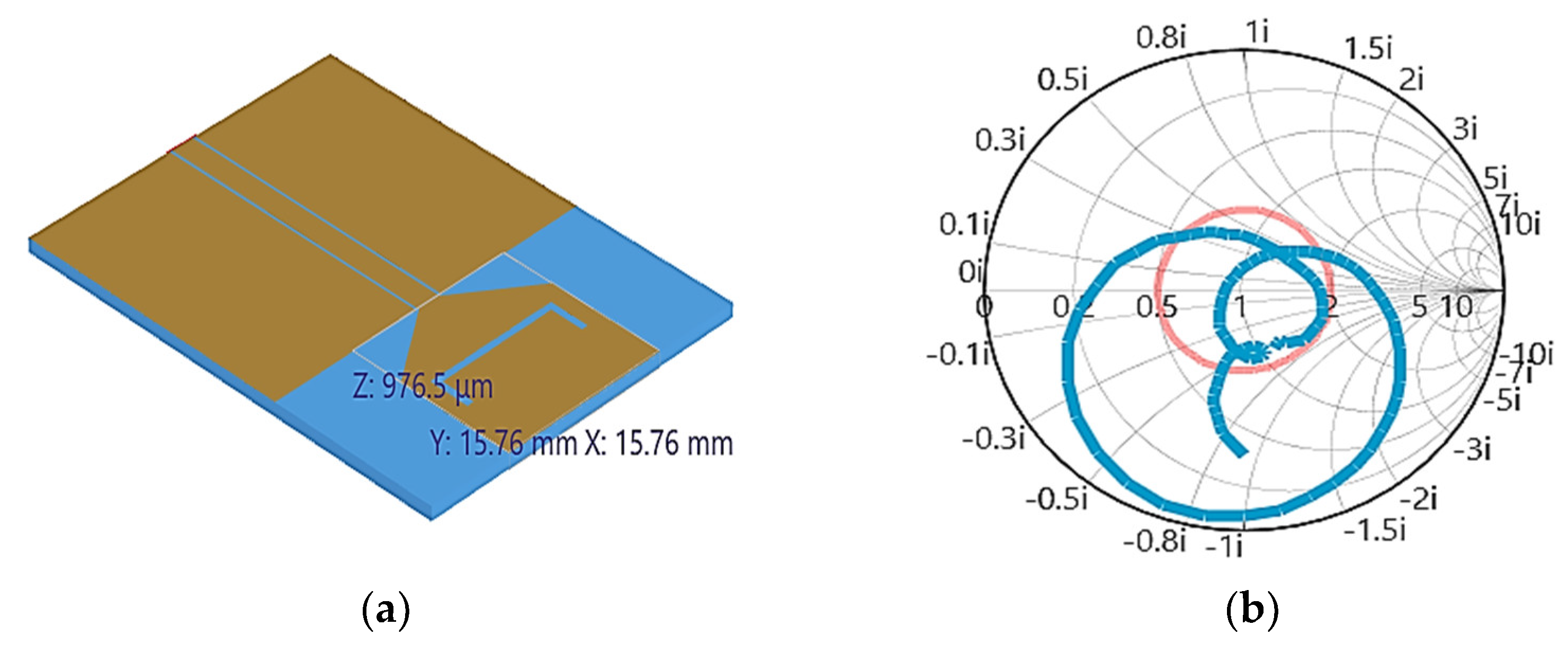
Figure 3 elevates the structural view of the proposed antenna, impedance smith chart plot and prototyped antenna on FR4 substrate material. An impedance value of 50 ohm is attained at resonant frequencies from Figure 3b and the dimensions of the prototyped antenna in millimetre.
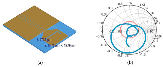
Figure 3.
Notch band Monopole, (a) Side View, (b) Smith Chart.
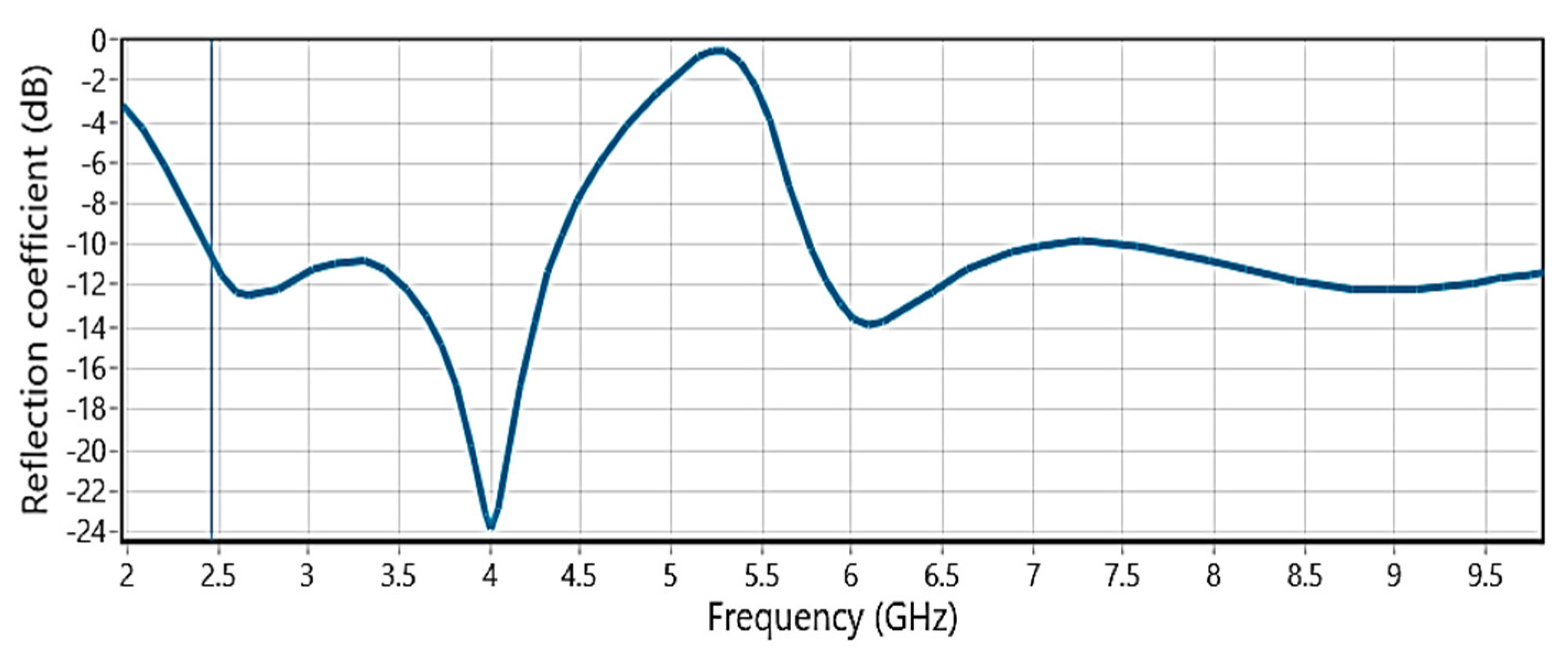
Figure 4 projects the scattering parameter S11 result of the designed antenna and the working range. Antenna resonating between 2.5–4.4 GHz with a 500 MHz bandwidth and 5.7–7 GHz with a bandwidth of 1000 MHz. A clear notching can be observed from 4.4–5.7 GHz with 1300 MHz bandwidth. Figure 5 shows the impedance plot of the antenna model with respect to the working and notch band. It projects the obtained impedance value of very high in the notch band.
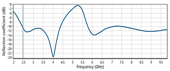
Figure 4.
Reflection coefficient of notch band monopole.
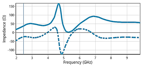
Figure 5.
Impedance plot with Frequency in GHz.
Figure 6 shows the simulated VSWR-Voltage standing wave ratio plot from the EM-tool and obtained measurement results of VSWR on an aniritsu combinational device analyser. The ratio of 2:1 is perfectly aligned in the operating region and in good matching with the simulation. Dotted line is idle impedance for reference and solid line is the original result which is attained from proposed method.
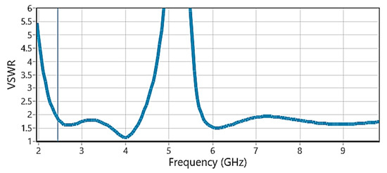
Figure 6.
VSWR values Measurement plot on screen.
The Peak Realized Gains at Different Frequencies
Different Frequency Peak Realised Gains: 2.5 GHz. At 2.5 GHz, the antenna has [Peak Gain Value] dBi. This gain number shows the antenna’s ability to focus and radiate signals at this frequency. An antenna with a higher gain at 2.5 GHz is well-optimized for this frequency and can provide improved coverage and signal propagation in this band. The solid line in above Figure 6 explains about VSWR variations at different frequencies.
3.4 GHz: The antenna’s peak gain is [Peak Gain Value] dBi at 3.4 GHz. Antenna efficiency in emitting 3.4 GHz signals is shown by this gain level. The antenna’s 3.4 GHz gain implies it can transmit and receive signals in this frequency band.
5.8 GHz: At 5.8 GHz, the antenna has [Peak Gain Value] dBi. The antenna’s 5.8 GHz performance and propagation are shown by this gain test. A high gain at 5.8 GHz indicates that the antenna can cover this spectrum well and communicate reliably.
Analysis: Peak realised gains at different frequencies demonstrate the antenna’s versatility and efficiency in processing signals across frequencies. A well-matched and optimised antenna with a high peak gain at a given frequency is useful for applications targeting that band. In modern wireless systems that operate in many frequency bands, the antenna’s ability to sustain reasonable gain values across different frequencies shows its versatility in multi-band communication settings. These gain values indicate the antenna’s radiation efficiency and signal propagation. Higher gains increase communication quality and coverage by strengthening, transmitting, and receiving signals. While the chosen keywords (ISM, LTE, Wi-MAX, WLAN) aptly reflect the antenna’s relevance, consider providing a context within the abstract about how the antenna aligns with and addresses the challenges in these communication technologies.
Radiation Analysis: Figure 7 projects the obtained radiation parameters of the antenna at three different operating bands collected from CST tool. Antenna showing 2.4 dB, 4.7 dB and 5.1 dB gain at 2.5, 3.4 and 4 GHz, respectively.
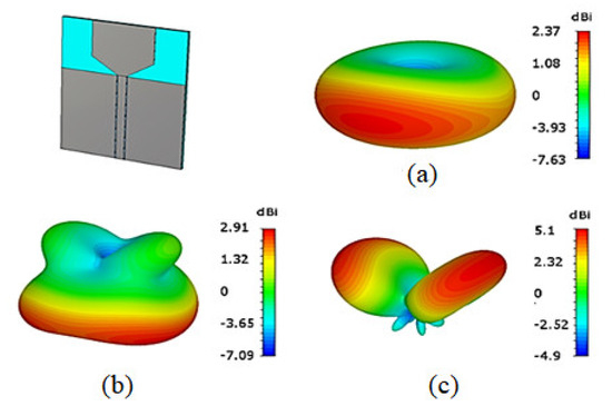
Figure 7.
Notch antenna 3D-Radiation at three bands, (a) 2.5 GHz, (b) 3.4 GHz, (c) 4 GHz.
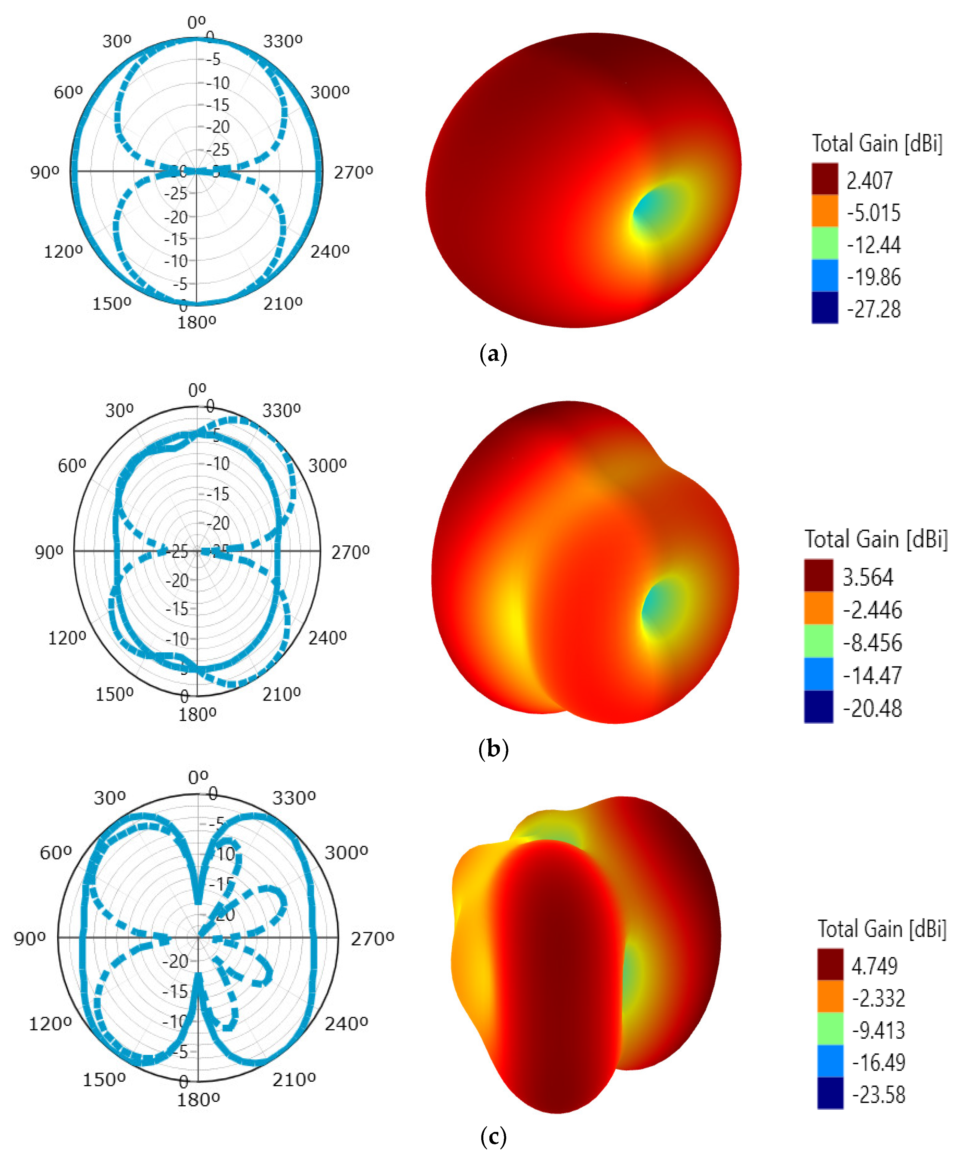
Figure 8 projects the radioactivity performance features of the proposed model at 3 different working groups that are taken from the Antenna magus tool. Antenna showing 2.4 dB, 3.5 dB and 4.7 dB gain at 2.5, 2.8 and 3.4 GHz, respectively. The polar as well as three dimensional representations are presented here for azimuthal and elevation angles.
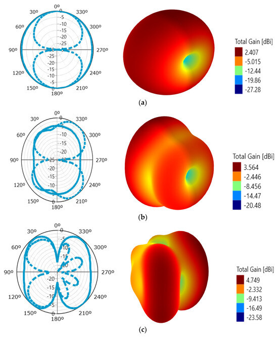
Figure 8.
Trapezoidal Notch Monopole Antenna: (a) gain ranges from 2.407 to −27.28 dB; (b) model exhibits a gain of 3.564 to −20.48 dB; (c) gain ranges from 4.749 to −23.58 dB.
3. Conclusions
A trapezoidal notch band monopole model projection is considered, analysed and articulated clearly. The designed antenna model is working at two operating bands and notching 4.4 to 5.7 GHz with 1.3 GHz bandwidth. The modelled antenna exhibit excellent impedance parameter characteristics at the operating frequencies with the nearest value to 50 ohm and high impedance values in notch band. The radiation characteristics are analysed from CST and the Antenna magus tool and presented the same with gain values. A maximum gain of 5.1 dB is attained in the operating band with directive pattern. The simulation-based results exhibit good matching with the measured parameter results on a combinational analyser in the chamber.
Author Contributions
Conceptualization by G.K.B.; methodology and validation was performed by K.S.N. and S.A.; writing as well as review by S.A. All authors have read and agreed to the published version of the manuscript.
Funding
This research received no external funding.
Institutional Review Board Statement
Not applicable.
Informed Consent Statement
Not applicable.
Data Availability Statement
The data can be obtained from the corresponding author on request.
Acknowledgments
We thank ALRC-R&D of KLEF for their support in the prototype and testing of the antenna.
Conflicts of Interest
The authors declare no conflicts of interest.
References
- Mohan Reddy, S.S.; Mallikarjuna Rao, P.; Madhav, B.T. Asymmetric defected ground structured monopole antenna for Wideband Communication Systems. Int. J. Commun. Antenna Propag. 2015, 5, 256–267. [Google Scholar] [CrossRef]
- Usman, M. Design of compact ultra-wideband monopole semi-circular patch antenna for 5G Wireless Communication Networks. Przegląd Elektrotechniczny 2019, 1, 225–228. [Google Scholar] [CrossRef]
- Nagre, S.S.; Shirsat, A.S. Design of compact CPW-fed printed monopole UWB antenna for band notched applications. In Proceedings of the 2016 International Conference on Automatic Control and Dynamic Optimization Techniques (ICACDOT), Pune, India, 9–10 September 2016. [Google Scholar]
- Rao, M.V.; Ramya, U.; Lakshman, P.; Prabhakar, V.S.V.; Madhav, B.T.P. Triple notch slotted monopole antenna with complementary split ring resonators. Int. J. Comput. Aided Eng. Technol. 2021, 15, 458–469. [Google Scholar] [CrossRef]
- Lu, G.; Yan, F.; Zhang, K.; Zhao, Y.; Zhang, L.; Shang, Z.; Diao, C.; Zhou, X. A dual-band high-gain subwavelength cavity antenna with artificial magnetic conductor metamaterial microstructures. Micromachines 2021, 13, 58. [Google Scholar] [CrossRef] [PubMed]
- Maji, A.; Choubey, G. Improvement of heat transfer through fins: A brief review of recent developments. Heat Transfer 2020, 49, 1658–1685. [Google Scholar] [CrossRef]
- Nejdi, I.H.; Das, S.; Rhazi, Y.; Madhav, B.T.; Bri, S.; Aitlafkih, M. A compact planar multi-resonant multi-broadband fractal monopole antenna for Wi-Fi, WLAN, Wi-Max, Bluetooth, LTE, S, C, and X band Wireless Communication Systems. J. Circuits Syst. Comput. 2022, 31, 225–237. [Google Scholar] [CrossRef]
- Al-Tamimi, M.; Mahdi, S. Design of double notch band half-elliptical shape reconfigurable antenna for UWB applications. Eng. Technol. J. 2019, 37, 85–89. [Google Scholar] [CrossRef]
- Yan, Y.; Li, L.; Zhang, J.; Hu, H.; Zhu, Y.; Chen, H.; Fang, Q. Design of Y-type branch broadband dual-polarization antenna and C-type slot line notch antenna. Prog. Electromagn. Res. M 2021, 106, 105–115. [Google Scholar] [CrossRef]
- Babu, K.V.; Das, S.; Ali, S.S.; El Ghzaoui, M.; Madhav, B.T.; Patel, S.K. Broadband sub-6 GHz flower-shaped MIMO antenna with high isolation using theory of characteristic mode analysis (TCMA) for 5G NR bands and Wlan Applications. Int. J. Commun. Syst. 2023, 36, 387–398. [Google Scholar] [CrossRef]
- Prasad, N.; Pardhasaradhi, P.; Madhav, B.T.; Das, S.; Awan, W.A.; Hussain, N. Flexible metamaterial-based frequency selective surface with square and circular split ring resonators combinations for X-band applications. Mathematics 2023, 11, 800. [Google Scholar] [CrossRef]
- Raghavendra, C.; Neelaveni Ammal, M.; Madhav, B.T.P. Metamaterial inspired square gap defected ground structured wideband dielectric resonator antenna for microwave applications. Heliyon 2023, 9, 210–221. [Google Scholar] [CrossRef] [PubMed]
- Sarma, C.A.; Inthiyaz, S.; Madhav, B.T. Design and assessment of bio-inspired antennas for Mobile Communication Systems. Int. J. Electr. Electron. Res. 2023, 11, 176–184. [Google Scholar] [CrossRef]
- Lanka, M.D.; Chalasani, S. Development of low profile M-shaped monopole antenna for Sub 6 GHz bluetooth, LTE, ISM, Wi-Fi and WLAN applications. Int. J. Intell. Eng. Syst. 2021, 14, 159–167. [Google Scholar]
- Kesana, S.; Srinivasa Babu, P.S.; Shameem, S. Design of quad-band antenna of 3.8 GHz range for Wi-Max Applications. In Proceedings of the 2021 IEEE International Conference on Mobile Networks and Wireless Communications (ICMNWC), Tumkur, India, 3–4 December 2021. [Google Scholar]
- Singh, G.; Singh, U. Triple-step feed line-based compact ultra-wideband antenna with quadruple band-notch characteristics. Int. J. Electron. 2022, 109, 271–292. [Google Scholar] [CrossRef]
- Rizvi Jarchavi, S.M.; Iqbal, M.; Dalarsson, M.; Alibakhshikenari, M.; Dayoub, I. Compact multi-band flexible antenna for ISM, WLAN, Wi-Fi, and 5G sub-6-ghz applications. In Proceedings of the 2022 3rd URSI Atlantic and Asia Pacific Radio Science Meeting (AT-AP-RASC), Gran Canaria, Spain, 30 May–4 June 2022. [Google Scholar]
- Saikumar, K.; Arulanantham, D.; Rajalakshmi, R.; Prabu, R.T.; Kumar, P.S.; Vani, K.S.; Ahammad, S.H.; Eid, M.M.; Rashed, A.N.; Hossain, M.A.; et al. Design and development of surface plasmon polariton resonance four-element triple-band multi-input multioutput systems for LTE/5G applications. Plasmonics 2023, 18, 1949–1958. [Google Scholar] [CrossRef]
- Vasimalla, Y.; Pradhan, H.S.; Pandya, R.J.; Saikumar, K.; Anwer, T.M.; Rashed, A.N.; Hossain, M.A. Titanium dioxide-2d nanomaterial based on the surface plasmon resonance (SPR) biosensor performance signature for infected red cells detection. Plasmonics 2023, 18, 1725–1734. [Google Scholar] [CrossRef]
- Nallagonda, S.; Roy, S.D.; Kundu, S.; Ferrari, G.; Raheli, R. Censoring-based cooperative spectrum sensing with improved energy detectors and multiple antennas in fading channels. IEEE Trans. Aerosp. Electron. Syst. 2018, 54, 537–553. [Google Scholar] [CrossRef]
- Sandeep, D.R.; Madhav, B.T.; Das, S.; Hussain, N.; Islam, T.; Alathbah, M. Performance analysis of skin contact wearable textile antenna in human sweat environment. IEEE Access 2023, 11, 62039–62050. [Google Scholar] [CrossRef]


Disclaimer/Publisher’s Note: The statements, opinions and data contained in all publications are solely those of the individual author(s) and contributor(s) and not of MDPI and/or the editor(s). MDPI and/or the editor(s) disclaim responsibility for any injury to people or property resulting from any ideas, methods, instructions or products referred to in the content. |
© 2024 by the authors. Licensee MDPI, Basel, Switzerland. This article is an open access article distributed under the terms and conditions of the Creative Commons Attribution (CC BY) license (https://creativecommons.org/licenses/by/4.0/).