Abstract
Due to the fast advancement of technology and industry, miniaturization has become an important research area. Also, all wired systems are shifting into wireless, and thus, there is a need for antennas to transmit and receive data in and out of gadgets. Fractal geometries provide many benefits when used to manufacture microstrip antennas, including features like size filling, multiband, low profile, and compact size. In this study, four fractal antennas, the Sierpinski carpet, Sierpinski gasket, circular patch, and Koch fractal, were designed. Three iterations of the above four antennas were completed. The size of the antennas was 20 mm × 26 mm × 1.6 mm. FR4 epoxy with a full ground was used here for antenna generation. These antennas can be used for 5 GHz band wireless applications. They provide a good return loss at 5.2 GHz. The maximum return loss was achieved using the Koch fractal at its 3rd iteration of −39.85 dB with a gain of 3.6 dB. In order to reduce cross-polarization, a square slot was added in all antennas’ feed lines, and cross-polarization was reduced by up to 60 dB. For simulation purposes, Ansys-HFSS, using FEM for the analysis of complex EM problems, provided accurate results. Also, 3D and 2D radiation patterns were analyzed, and it was found that they were directional in nature with low radiation toward the back side.
1. Introduction
Fractals are the new area in antenna study, and with the advent of wireless communication systems comes the ever-increasing importance of manufacturing small-sized antennas and multiband applications that are in greater demand for civilian and defense applications. Fractal antennas are a variant of MSPA, which is low profile and can be manufactured on a PCB. As it is a miniature size, it can be fixed in any small gadget. It provides mechanical robustness as it is self-similar; the failure of one part may be compensated for using the other part. It consists of several iterations of a single elementary shape having the inherent properties of self-similarity and space-filling [1]. The advent of fractal geometry antennas has provided an answer to the two main limitations of classical antennas identified by Werner (1999), namely, their narrow-band nature and the frequency dependency on size [2]. Fractals are generally self-similar and scale-independent. Fractal antennas are needed for the following reasons:
- They have wideband and multiband frequency responses.
- They are reduced in size compared to traditional antennas.
- They have mechanical simplicity and strength.
- The properties of fractal antennas depend on geometry, not discrete additions.
The limitations that may be encountered during the design and testing of the complexity and numerical limitations of fractal antenna when moving from lower- to higher-order iterations are illustrated in Table 1.

Table 1.
Microstrip patch vs. fractal antennas.
Amrollah Amini proposed a compact square fractal antenna [3] for UWB services around the frequency range 3.1 Ghz to 10.6 Ghz, which can be used for medical imaging and UWB RADAR applications. Log periodic antenna, along with fractal geometry, provided a compact size for the antenna in that work, as presented in Table 2.
A hybrid antenna composed of Sierpinski and Koch shapes proposed by Wen-Ling Chen [4] achieved an approximate 77.1% size reduction and can be used for low-profile wireless systems. Another miniaturized fractal antenna, proposed by Abhik Gorai [5] for UWB wireless applications, and with band rejection at 5.5 GHz, exhibits constant group delay. Carles Puente Baliarda et al. explain how a Koch can be used to make small antennas [6] with highly-convoluted curves. A fractal Hilbert curve, using space-filling for miniaturization, has been suggested by Jaume Anguera et al. [7].
A super wideband antenna based on fractal geometry proposed by Abolfazl Azari [8] can be used for military communication using an orthogonal fractal micostrip for antenna generation. It provides approximately 40 GHz bandwidth. The wideband antenna proposed by Mahdi Naghshvarian [9] is a planar type with PGK fractals. This antenna finds applications in pulse communication, Wi-Fi, etc. [10]. Another UWB hybrid antenna composed of Giuseppe Peano fractals using Sierpinski carpet geometry proposed by Homayoon Oraizi [11] has an omni-directional radiation pattern and can be used for WLAN applications.
Multiband behavior enables gadgets to use the same antenna to receive many applications. The conical monopole generated from a Sierpinski gasket presented by Steven R. Best [12] offers a good impedance match with a directional pattern, and is a good candidate for wireless application. An H-shaped antenna generated using the PSO optimization technique proposed by [13] provides multiple resonances that can be used for 2.45/5.5 GHz WLAN applications. Circularly polarized antenna generated using a square and Giuseppe Peano fractal provides multiband and compact size, as explained by Homayoon Oraizi [14], for multiple wireless applications. A dual band antenna for WLAN application at 2.45 GHz and 5.4 GHz, as explained by Joan Gemio [15], is generated on a mod-2 Sierpinski gasket ground plane. A Sierpinski fractal derived from the Pascal triangle also provides multiple resonances, as proposed by Jordi Romeu [16], who explains how the number of iterations is related to the number of bands [17]. A hexagonal fractal for multiband is explained by P. W. Tang [18].
Table 2.
Methods used to achieve wideband and multiband frequencies.
Table 2.
Methods used to achieve wideband and multiband frequencies.
| Paper Title | Author | Ref. No. | Method Used | Multiband/ Wideband |
|---|---|---|---|---|
| A New Super Wideband Fractal Microstrip Antenna | Abolfazl Azari | [8] | Octagonal fractal geometry | Wideband |
| Novel Wideband Planar Fractal Monopole Antenna | Mahdi Naghshvarian et al. | [9] | Penta-Gasket-Koch with partial ground | Wideband |
| Miniaturized UWB Monopole Microstrip Antenna Design by the Combination of Giuseppe Peano and Sierpinski Carpet Fractals | Homayoon Oraizi et al. | [11] | Hybrid fractal geometry with partial ground | Ultra-wideband |
| Dual-Band Antenna with Fractal-Based Ground Plane for WLAN Applications | Joan Gemio et al. | [15] | Ground plane fractal-based rather than a solid one | Multiband |
| Generalized Sierpinski Fractal Multiband Antenna | Jordi Romeu et al. | [16] | Derived fractal mod—P Sierpinski gaskets | Multiband |
1.1. Antenna Gain and Efficiency
Antennas have a relative gain, which is the ratio of the radiation intensity in a particular direction to the power radiated in that direction by an isotropic antenna. If the power given to an isotropic antenna is P0, and emitted power by an isotropic antenna at R distance is shown in Equation (1) as
it is considered that the efficiency of the isotropic radiator is 100%.
1.2. Radiation Pattern
The pattern of an antenna is a far-field component, and it can be either a power pattern or an intensity pattern using special coordinates; that is, in terms of θ and φ, it can be considered as the power-radiated-per-unit solid angle.
1.3. Return Loss
Return loss is a parameter that is an indication of how much power is radiated. As per the power theorem, if the antenna is matched with the transmitter, the maximum radiation will occur. For a good antenna, the S11 should be in maximum –direction. The more S11 becomes negative, the better the antenna will be
1.4. Directivity
Directivity is the antenna parameter that describes the maximum radiation in a particular direction. Directive gain is the product of the efficiency and directivity of the antenna. That is, the gain and beamwidth are inversely proportional. Directivity in terms of θ and ϕ can be described in Equation (2) as
2. Methodology
2.1. Sierpinski Carpet Geometry
Sierpinski carpet geometry has a rectangular initiator, and in order to make the 1st iteration, the initiator is divided into nine equal squares. The middle one is eliminated, and the rest are all united. Likewise, we can generate higher-order iterations. Figure 1 shows four iterations; i.e., the 1st, 2nd, 3rd, and 4th iterations of a Sierpinski fractal geometry.
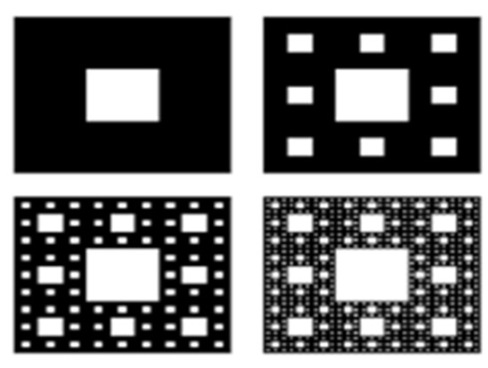
Figure 1.
Sierpinski carpet iterations.
2.2. Sierpinski Gasket Geometry
Sierpinski gasket geometry is a triangular fractal in which the initiator is a triangle. For the first iteration, divide the initiator into 4 equilateral triangles and subtract the middle one. For the 2nd iteration, make the remaining triangles into 4 equilateral triangles each and subtract the middle ones. Figure 2 shows the initiator and up to the 3rd iteration of the gasket antenna.

Figure 2.
Sierpinski gasket iterations.
2.3. Sierpinski Circular Geometry
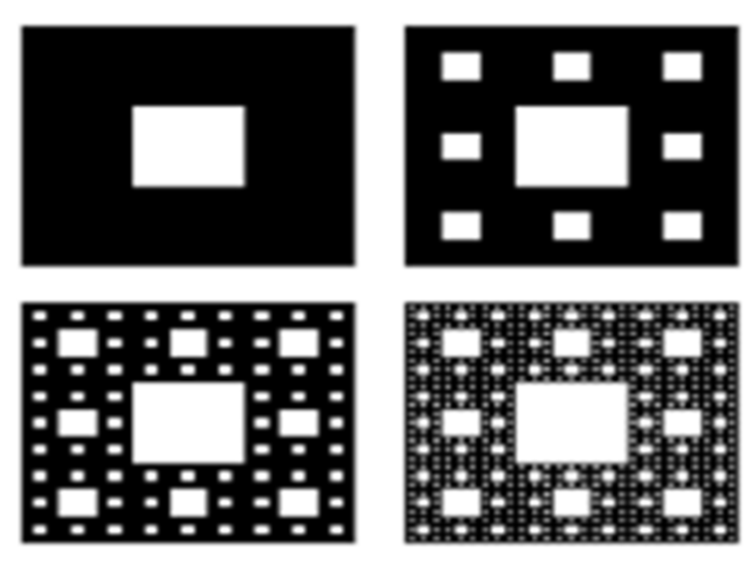
To produce Sierpinski circular fractal geometry, the initiator used is a circle, and to make the 1st iteration, the initiator is scaled down to 1/3rd size and subtracted from the initiator. Figure 3 shows the initiator and higher-order iterations of circular fractal geometry.

Figure 3.
(a) Initiator (b) 1st Iteration (c) 2nd Iteration (d) 3rd iteration of Circular fractal.
2.4. Koch Fractal Antenna
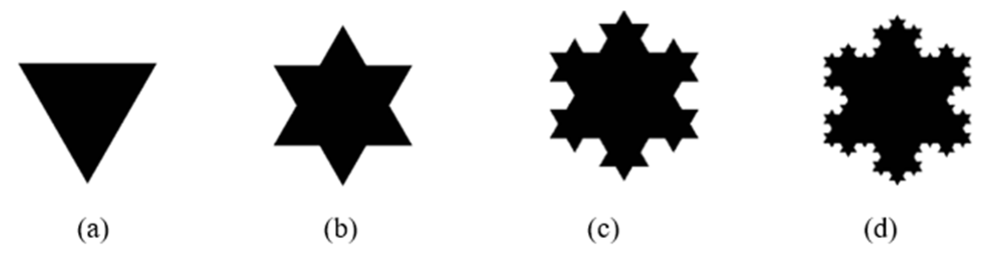
The Koch fractal is an extension of the Koch curve. But here the initiator used is a triangle, and the initiator is scaled down to 1/3rd size and is added to all sides of the initiator to make the 1st iteration. Figure 4 shows the initiator and higher-order iterations of Koch fractal geometry.

Figure 4.
(a) Initiator (b) 1st Iteration (c) 2nd Iteration (d) 3rd iteration of Koch fractal.
2.5. Antenna Design
The proposed antennas were designed to resonate at a 5.2 GHz frequency, the same frequency applied for Wi-Fi applications. In order to simulate the proposed antennas, Ansys-HFSS was used, which uses the method of moments for simulation, as shown in Table 3. After generating the fractal geometry in HFSS, analysis was undertaken to find the values of S11, VSWR, gain, radiation pattern, etc. [19,20]. All parameters were found to be good, and the antennas could be used for Wi-Fi applications at 5.2 GHz.
Table 3.
Antenna design frequencies.
3. Methodology
3.1. Sierpinski Carpet Antenna
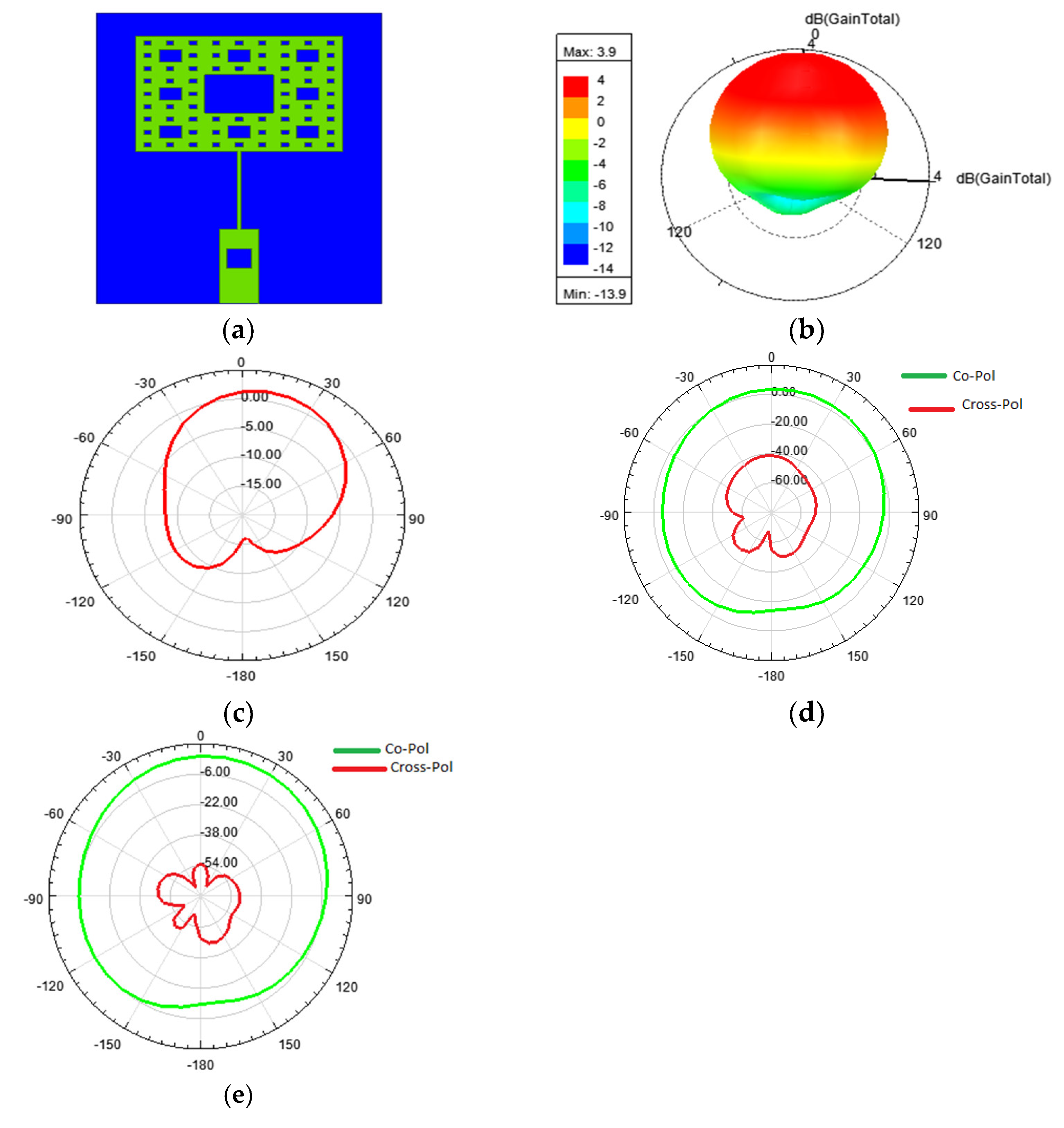
Figure 5a,b depict the Sierpinski carpet antenna, in which better impedance matching was obtained by adding an 8 mm long matching strip line, along with a 7.667 mm feed line having a 50 Ω impedance. The return losses obtained were −28.5 dB at 5.2 Ghz, and −27.98 dB at 8.3 GHz, as shown in Figure 3c. A cross-polarization reduction up to −53.23 dB was achieved by adding a square slot on the feed line, as shown in Figure 5d,e.
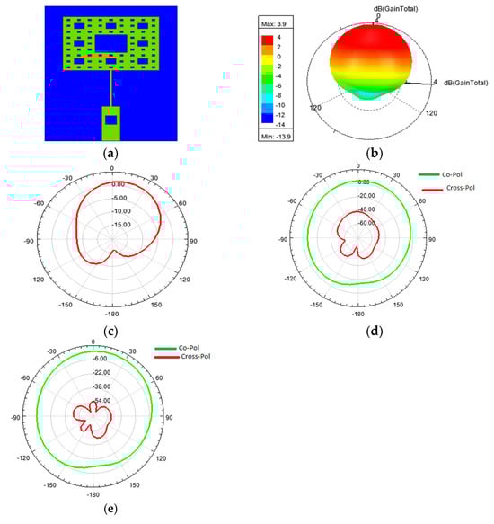
Figure 5.
(a) Designed Sierpinski carpet fractal antenna in Ansys-HFSS; (b) gain plot; (c) radiation pattern; (d) co- and cross-polarization of Sierpinski carpet without a slot on the feed; and (e) co- and cross-polarization of Sierpinski carpet with a slot on the feed.
3.2. Sierpinski Circular Antenna
In the circular fractal antenna, better impedance matching was obtained by adding a 5.5 mm long matching strip line, along with a 4 mm feed line having a 50 Ω impedance, as illustrated in Figure 6a,b. The return loss obtained was −40.38 dB at 5.2 GHz, which is represented in Figure 6c. A cross-polarization reduction up to −27 dB was achieved by adding a square slot on the feed line, whereas without a slot, it was found to be −23 dB, as represented in Figure 6d,e.
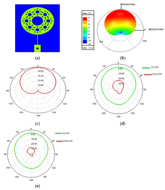
Figure 6.
(a) Designed circular fractal antenna in Ansys-HFSS; (b) gain plot; (c) radiation pattern; (d) co-and cross-polarization of circular fractal antenna without a slot on the feed; and (e) co- and cross-polarization of circular fractal antenna with a slot on the feed line.
3.3. Sierpinski Gasket Antenna
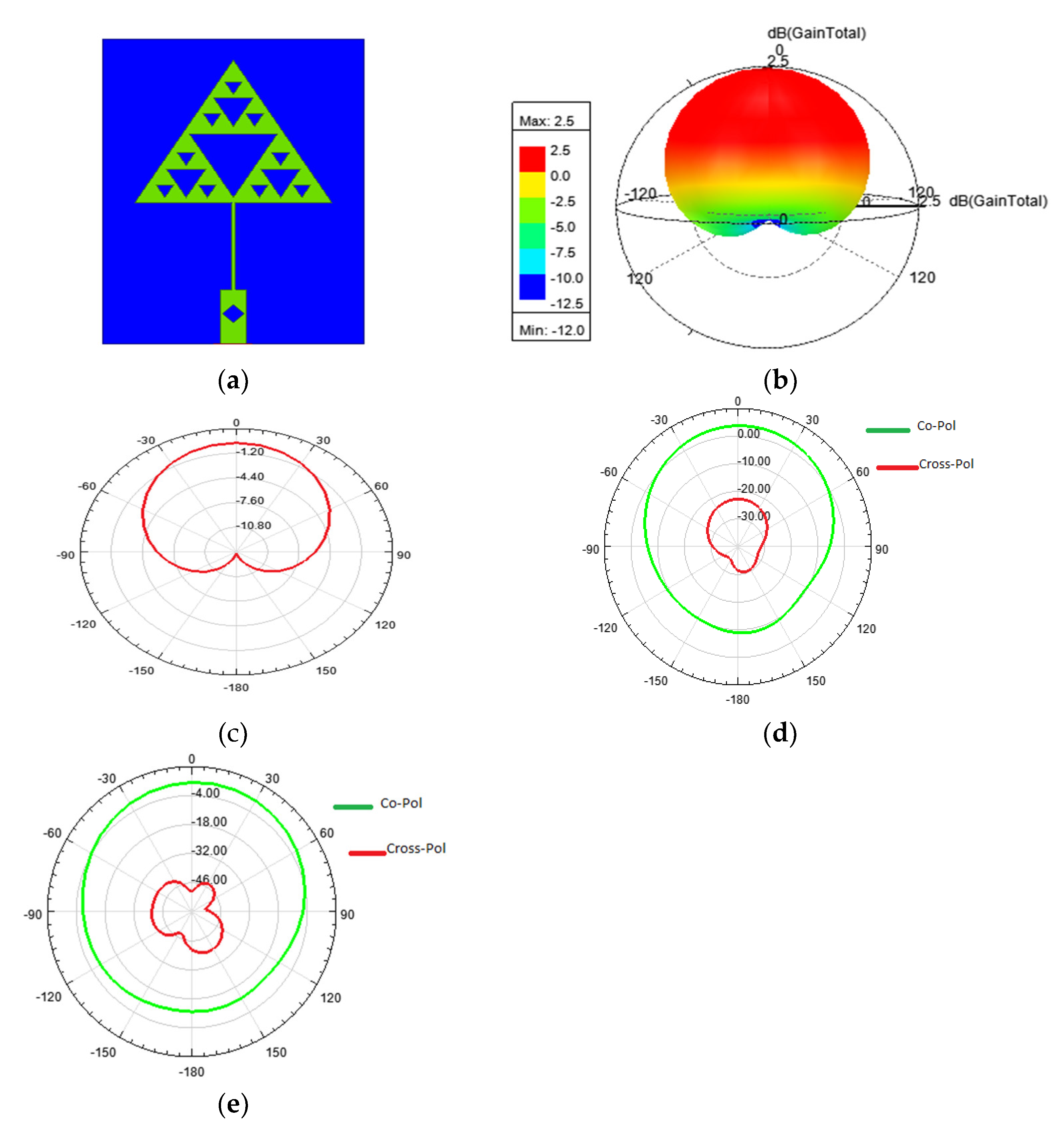
In the Sierpinski gasket fractal antenna, better impedance matching was obtained by adding a matching 8 mm long strip line, along with a 5 mm feed line having a 50 Ω impedance, as illustrated in Figure 7a,b. The return loss obtained was −28.37 dB at 5.2 GHz, as shown in Figure 7c. A cross-polarization reduction up to −50.34 dB was achieved by adding a square slot on the feed line, whereas without a slot, it was found to be −17.52 Db, as shown in Figure 7d,e.

Figure 7.
(a) Designed Sierpinski gasket fractal antenna in Ansys-HFSS; (b) gain plot; (c) radiation pattern; (d) co- and cross-polarization of Sierpinski gasket antenna without a slot on the feed; and (e) co- and cross-polarization of Sierpinski gasket antenna with a slot on the feed line.
3.4. Koch Fractal Antenna
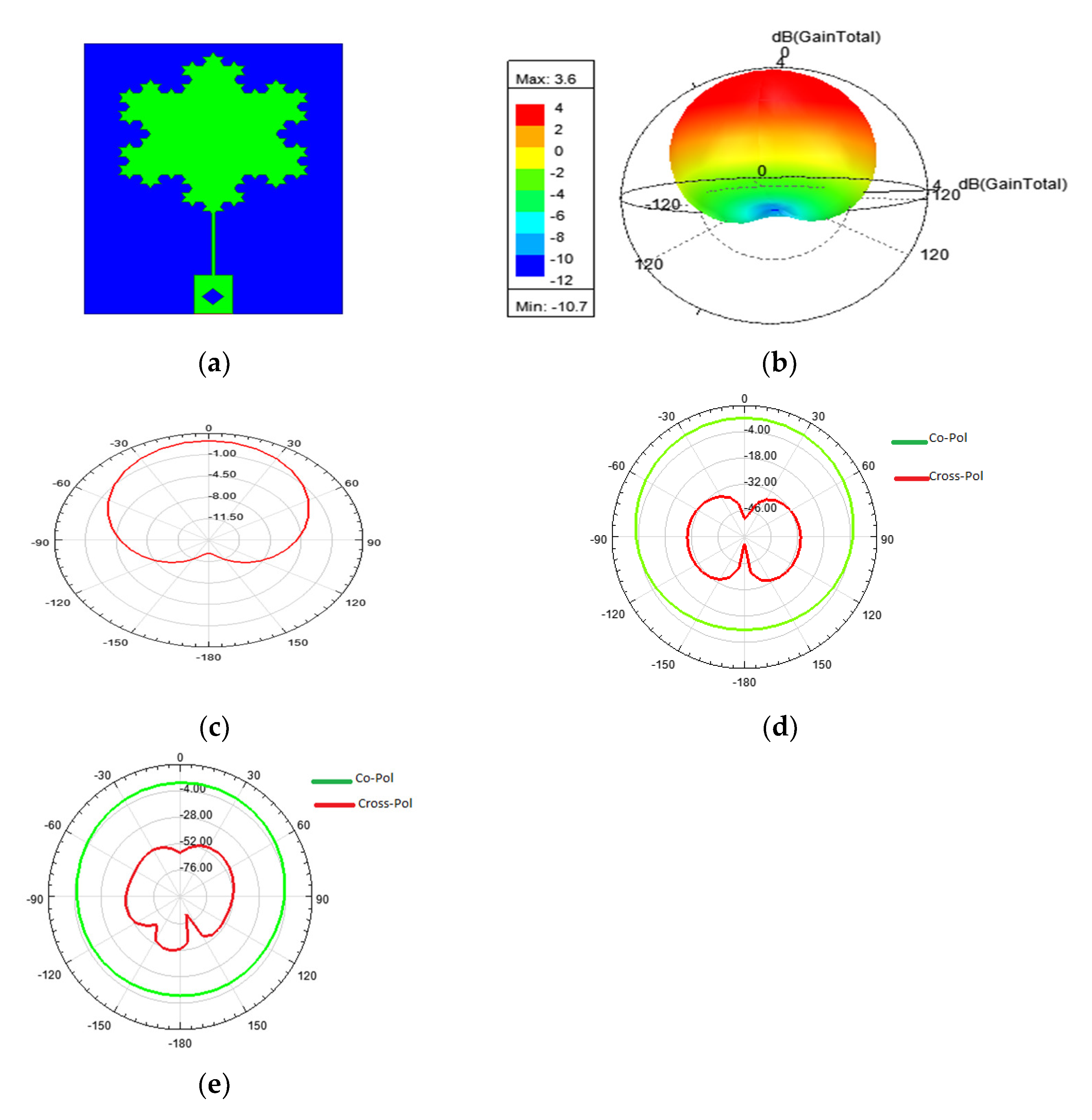
Figure 8a,b depict the Koch fractal antenna, in which better impedance matching was obtained by adding a matching 6.4 mm long strip line, along with a feed line of 4 mm having a 50 Ω impedance, as shown in Figure 6c. The return loss obtained was −44.38 dB at 5.2 GHz. A cross-polarization reduction up to −60 dB was achieved by adding a square slot on the feed line, whereas without a slot, it was found to be −50 dB, as shown in Figure 8d,e.
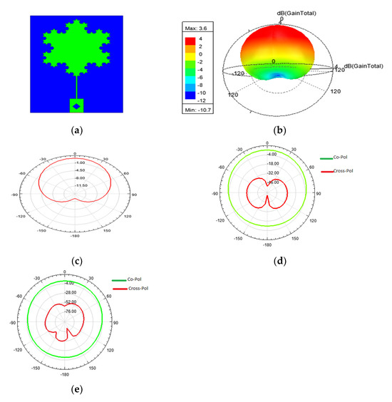
Figure 8.
(a) Designed 3rd iteration of the Koch fractal antenna in Ansys-HFSS; (b) gain plot; (c) radiation pattern; (d) co- and cross-polarization of Koch fractal antenna without a slot on the feed line; and (e) co- and cross-polarization of Koch fractal antenna with a slot on the feed line.
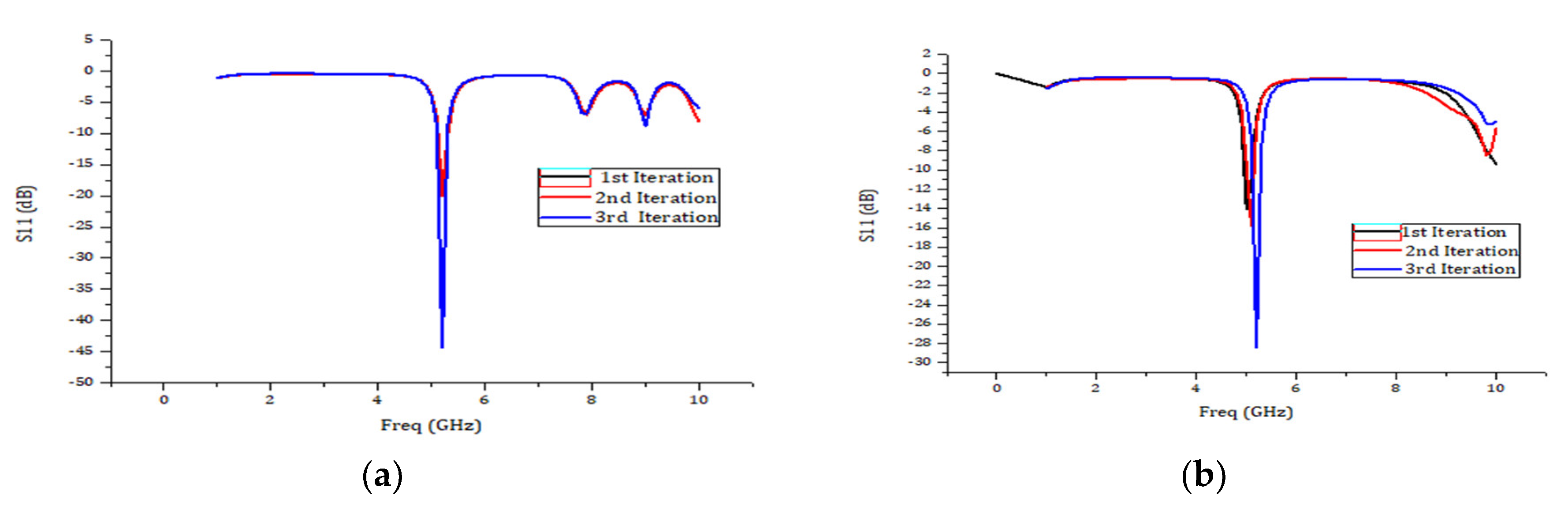
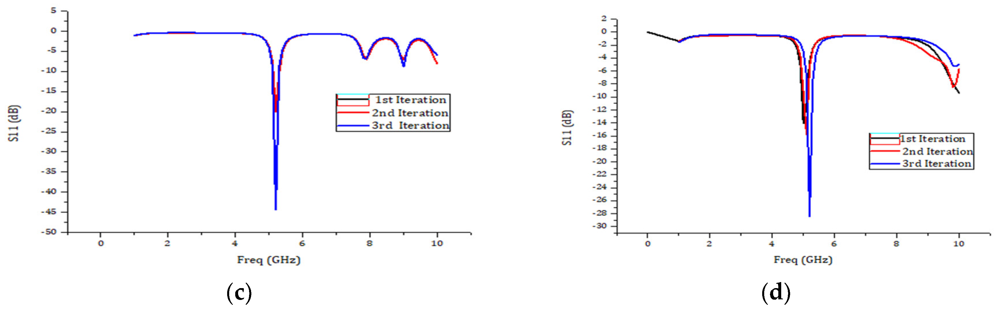
Figure 9 shows the combined S11 plots of all three iterations for the antenna designed and from this it is evident that these antennas are good for 5GHz wireless application.
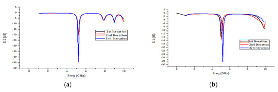
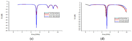
Figure 9.
(a) Combined S11 plot of all three iterations of Koch fractal antenna; and (b) combined S11 plot of all three iterations of Sierpinski gasket antenna. (c) Combined S11 plot of all three iterations of circular fractal antenna; and (d) combined S11 plot of all three iterations of Sierpinski carpet antenna.
4. Conclusions
Fractal geometries are best for miniaturization and multiband applications when used as an antenna. Fractal consists of its own smaller or larger version, which enables the above-mentioned miniaturization and multiband advantages. In order to achieve cross-polarization minimization, a new method is proposed; i.e., adding a square slot in the feed line. The results show that, using this addition, cross-polarization up to −60 dB can be achieved for different proposed antennas.. We can also use fractal geometry for wideband and UWB antenna generation and for MIMO antenna generation. Here, the proposed antennas are very compact and have good radiation properties, which enable them to be used for 5.2 GHz Wi-Fi applications.
Author Contributions
Conceptualization, S.V.S., S.R., J.K.N.V. and S.A.S.; methodology, S.V.S. and S.R.; software, J.K.N.V. and S.R.; validation, S.R. and J.K.N.V.; formal analysis, J.K.N.V. and S.R.; writing—original draft preparation, S.R.; writing—review and editing, S.V.S. and S.R.; visualization, S.R.; supervision, J.K.N.V. All authors have read and agreed to the published version of the manuscript.
Funding
This work did not receive funding from any source.
Institutional Review Board Statement
Not applicable.
Informed Consent Statement
Not applicable.
Data Availability Statement
Data can be obtained from the corresponding author on request.
Acknowledgments
We acknowledge the institutional management and family members for their immense support.
Conflicts of Interest
The authors and coauthors declare no conflicts of interest.
References
- Mandelbrot, B.B. The Fractal Geometry of Nature; WH Freeman: New York, NY, USA, 1983; Volume 1, pp. 1–14. [Google Scholar]
- Werner, D.H.; Ganguly, S. An overview of fractal antenna engineering research. IEEE Antennas Propag. Mag. 2003, 45, 38–57. [Google Scholar] [CrossRef]
- Amini, A.; Oraizi, H.; Zadeh, M.A. Miniaturized UWB Log-Periodic Square Fractal Antenna. IEEE Antennas Wirel. Propag. Lett. 2015, 14, 1322–1325. [Google Scholar] [CrossRef]
- Fractal-Shapes, S.; Chen, W.; Wang, G.; Zhang, C. Small-Size Microstrip Patch Antennas Combining. IEEE Antennas Wirel. Propag. Lett. 2009, 7, 738–741. [Google Scholar]
- Gorai, A.; Pal, M.; Ghatak, R. A compact fractal-shaped antenna for ultra-wideband and Bluetooth wireless systems with WLAN rejection functionality. IEEE Antennas Wirel. Propag. Lett. 2017, 16, 2163–2166. [Google Scholar] [CrossRef]
- Baliarda, C.P.; Romeu, J.; Cardama, A. The Koch monopole: A small fractal antenna. IEEE Trans. Antennas Propag. 2000, 48, 1773–1781. [Google Scholar] [CrossRef]
- Anguera, J.; Puente, C.; Soler, J. 2002 IEEE Antennas and Propagation Society International Symposium. IEEE Antennas Propag. Soc. AP-S Int. Symp. 2002, 1, 546–549. [Google Scholar]
- Azari, A. A new super wideband fractal microstrip antenna. IEEE Trans. Antennas Propag. 2011, 59, 1724–1727. [Google Scholar] [CrossRef]
- Naghshvarian-Jahromi, M. Novel wideband planar fractal monopole antenna. IEEE Trans. Antennas Propag. 2008, 56, 3844–3849. [Google Scholar] [CrossRef]
- Vargas, I.M.; Luy-Montejo, C.; Alcaide-Aranda, L.I.D.C.; Parks, D.I.G.; Cruz, Y.M.M.; Palacios-Garay, J.P.; Carmen Gonzales-Sánchez, A. Improved Butterfly Optimization Algorithm for Energy Efficient Antenna Selection Over Wireless Cellular Networks. J. Wirel. Mob. Netw. Ubiquitous Comput. Dependable Appl. 2023, 14, 121–136. [Google Scholar] [CrossRef]
- Oraizi, H.; Hedayati, S. Miniaturized UWB monopole microstrip antenna design by the combination of Giuseppe Peano and Sierpinski carpet fractals. IEEE Antennas Wirel. Propag. Lett. 2011, 10, 67–70. [Google Scholar] [CrossRef]
- Best, S.R. A multiband conical monopole antenna derived from a modified Sierpinski Gasket. IEEE Antennas Wirel. Propag. Lett. 2003, 2, 205–207. [Google Scholar] [CrossRef]
- Weng, W.C.; Hung, C.L. An H-fractal antenna for multiband applications. IEEE Antennas Wirel. Propag. Lett. 2014, 13, 1705–1708. [Google Scholar] [CrossRef]
- Oraizi, H.; Hedayati, S. Circularly polarized multiband microstrip antenna using the square and guiseppe peano fractals. IEEE Trans. Antennas Propag. 2012, 60, 3466–3470. [Google Scholar] [CrossRef]
- Gemio, J.; Granados, J.P.; Castany, J.S. Dual-band antenna with fractal-based ground plane for WLAN applications. IEEE Antennas Wirel. Propag. Lett. 2009, 8, 748–751. [Google Scholar] [CrossRef]
- Romeu, J.; Soler, J. Generalized Sierpinski fractal multiband antenna. IEEE Trans. Antennas Propag. 2001, 49, 1237–1239. [Google Scholar] [CrossRef]
- Uchida, N.; Ito, K.; Ishida, T.; Shibata, Y. Adaptive Array Antenna Control Methods with Delay Tolerant Networking for the Winter Road Surveillance System. J. Internet Serv. Inf. Secur. 2017, 7, 2–13. [Google Scholar]
- Tang, P.W.; Wahid, P.F. Hexagonal fractal multiband antenna. IEEE Antennas Wirel. Propag. Lett. 2004, 3, 111–112. [Google Scholar] [CrossRef]
- Prasad, R.H.; Vakula, D.; Chakravarthy, M. A novel fractal slot DGS microstrip antenna for Wi-Fi application. In Proceedings of the 2018 IEEE Indian Conference on Antennas and Propogation (InCAP), Hyderabad, India, 16–19 December 2018; pp. 1–4. [Google Scholar]
- Marzouk, M.; Rhazi, Y.; Nejdi, I.H.; Zerrad, F.E.; Saih, M.; Ahmad, S.; Ghaffar, A.; Hussein, M. Ultra-Wideband Compact Fractal Antenna for WiMAX, WLAN, C and X Band Applications. Sensors 2023, 23, 4254. [Google Scholar] [CrossRef] [PubMed]


Disclaimer/Publisher’s Note: The statements, opinions and data contained in all publications are solely those of the individual author(s) and contributor(s) and not of MDPI and/or the editor(s). MDPI and/or the editor(s) disclaim responsibility for any injury to people or property resulting from any ideas, methods, instructions or products referred to in the content. |
© 2023 by the authors. Licensee MDPI, Basel, Switzerland. This article is an open access article distributed under the terms and conditions of the Creative Commons Attribution (CC BY) license (https://creativecommons.org/licenses/by/4.0/).