Abstract
The increasing demand for electricity has put a strain on existing power transmission and distribution systems. As a result, utilities are often forced to overload their existing systems, which can lead to voltage instability, transmission line congestion, and even blackouts. To fix these problems, flexible AC transmission system controllers (FACTs) can be used. This paper deals with two objectives: minimizing voltage deviation and real power losses, and the minimization has been performed using the multi-objective artificial bee colony algorithm (MOABC). UPFC has been optimally placed on the IEEE bus-39 system. The proposed work is implemented through MATLAB coding.
1. Introduction
The power grid in many parts of the world is struggling to keep up with the increasing demand for electricity. Therefore, utilities are often overloading their existing capacity, causing problems like transmission line losses and voltage instability. The integration of FACTs controllers will help reduce power losses, improve voltage stability, and manage congestion in electrical grids [1,2]. FACT devices should be strategically placed at locations where they can control the power flow and minimize transmission losses the most. Determining the best location for UPFC poses a significant challenge, even when solely considering steady-state conditions. Achieving optimal UPFC placement requires evaluating all potential system configurations and considering the range of possible control settings [3].
In recent research [4], a hybrid approach has been suggested to enhance stability by determining the optimal placement and size of UPFC. In this method, the bus with the highest losses is recognized as the best location for installing the UPFC. Laifa, et al. [5] have proposed a modified particle swarm optimization technique to determine the optimal placement and parameter configuration of the UPFC device. The objective was to improve the system’s performance by mitigating overloaded lines. Mahadevan, et al. [6] have incorporated a hybrid algorithm combining the ABC algorithm and the differential algorithm to achieve the best location of FACTs controllers on the IEEE bus-30 system. A genetic algorithm has been proposed as a solution for the optimal placement problem of UPFC [7]. Domínguez-Navarro, et al. [8] have demonstrated the utilization of evolutionary strategies for the optimal setting of control variables in FACTS. In this study, we employed a multi-objective ABC algorithm (MOABC) to minimize voltage deviation and power losses. The decision to employ the MOABC algorithm was primarily based on its capability to provide high-quality solutions and rapid convergence for single-objective optimization. The convergence of multiple objectives was analyzed by examining the Pareto front.
2. Problem Formulation
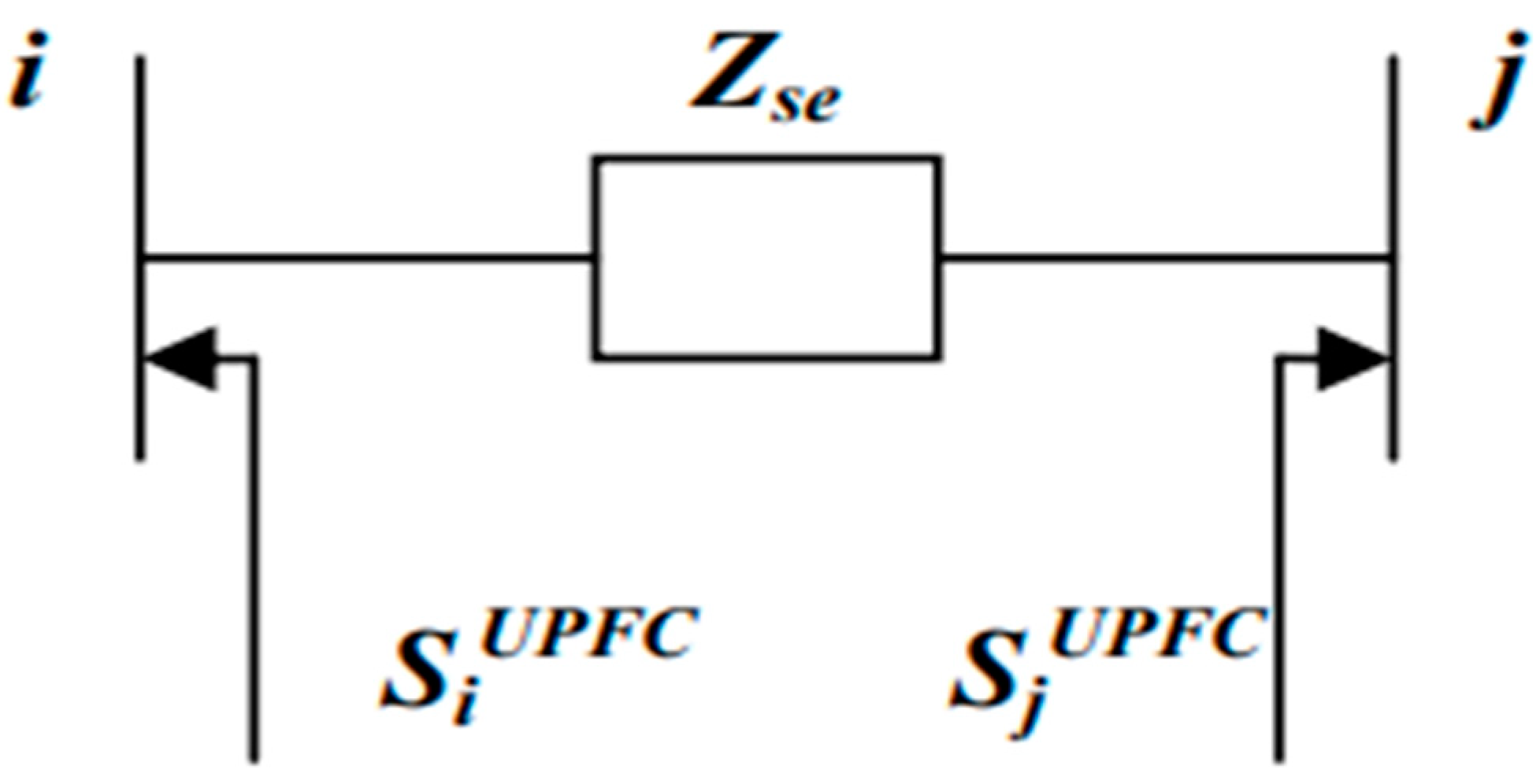
This research focuses on optimizing the location and parameter settings of the UPFC by utilizing a MOABC algorithm. The objective functions considered are reducing voltage deviation and minimizing power losses. Equations (1) and (2) are employed to minimize the total voltage deflection and actual power losses, respectively.
where VD represents voltage deviation, Ploss represents actual power losses, nbranch represents the number of lines, represents conductance of the line, nPQ represents the number of load buses, and representsthe voltage at the terminal buses of k and m of the ith line.
2.1. UPFC Modeling
The Unified Power Flow Controller (UPFC) is a crucial element in FACTs. It possesses the capability to regulate both active and reactive power transmission. The accompanying illustration, depicted in Figure 1, showcases the relevant equivalent schematic. The arrangement encompasses a pair of switching converters, which establish connections to the power system by coupling transformers. One converter is situated in series between the sending and receiving ends, while the other is connected in parallel at the sending end [9]. The steady-state model of the UPFC is derived using its equivalent circuit, which can be found in Figure 2 and power flow equation from Figure 3.
where = .
Figure 1.
UPFC Device.
Figure 2.
Equivalent Circuit of UPFC.
Figure 3.
UPFC model for power injection.
These are the control parameters of UPFC that are to be optimized.
In the given context, represents the voltage injected into the transmission line, while represents the angle associated with this voltage. Iq pertains to the reactive current in the shunt component of the UPFC. The values of , , and Iq are selected within certain limits imposed by physical and economic constraints. By using these control variables, power injection by UPFC is possible. The power injection equations and modification of the Jacobean are taken from [5].
2.2. Multi-Objective ABC Algorithm (MOABC)
In numerous engineering problems, it is difficult to encounter optimization problems that involve multiple objective functions. The objective is to discover solutions that strike a balance between these objectives [10]. Multiple techniques exist for multi-objective optimization, encompassing sub-population, Pareto-based, and hybrid methods. While various approaches are available, a significant portion of the research in this field concentrates on Pareto-based methodologies. Nevertheless, there exist a handful of strategies that utilize the behavior of honeybees to optimize multi-objective problems [11]. The ABC algorithm has recently introduced evolutionary methods [12,13]. The ABC algorithm demonstrates its suitability for multi-objective optimization primarily due to its high-quality solution and fast convergence rate observed in single-objective optimization. In this paper, we have used a method called the multi-objective artificial bee colony, which incorporates various types of bees and an archive to preserve excellent solutions [5]. The parameters of MOABC for optimization are shown in Table 1
Table 1.
Parameters for MOABC.
2.3. Selection of the Optimal Location and Parameter Settings of the UPFC
In this study, four variables are optimized. First is the location of UPFC, which can be anywhere in the line. Second is the series voltage ( which ranges from [0.001 to 0.1]; third is the phase angle () of series voltage source, which ranges from [0, 2π]; and fourth is the shunt reactive current (Iq), which ranges from [−0.10, 0.10]. The UPFC data is taken from [8].
3. Results
The IEEE bus-39 system has been adopted. It is comprised of 46 branches, 10 generator buses, and 29 load buses. Table 2 shows the optimal parameter values given by the ABC Algorithm. Results from Figure 4a show real power losses before and after the optimal placement of UPFC on each branch. Results from Figure 4b show that voltage deviation was also reduced on each load bus. The total voltage deviation after UPFC was reduced to 16.7%, while losses were also reduced considerably. Overall, the results demonstrate that the optimal placement of UPFC improves the efficiency of the system and minimizes real power losses. The successful results obtained from the optimal placement of UPFC in the 39 bus system highlight the effectiveness of this technology in addressing key challenges faced by power systems. The reduction in real power losses and voltage deviation has significant implications for the overall efficiency, reliability, and stability of the system. By strategically placing UPFC devices, the system can effectively manage power flow and voltage profiles, minimizing losses and maintaining voltage stability.
Table 2.
Optimal location and parameter settings obtained by multi-objective ABC.

Figure 4.
(a) The graph depicting real power losses before and after the implementation of the UPFC device reveals reductions in losses at each line. The blue bar shows real power losses before UPFC, and the yellow bar shows them after UPFC. This outcome demonstrates the effectiveness of the UPFC in improving system efficiency and minimizing power loss. (b) This outcome signifies the successful role of the UPFC in regulating and stabilizing the system voltage, leading to improved voltage profiles and minimized deviations across the system. The blue line shows voltage deviation before UPFC, and the red line shows voltage deviation after UPFC. (c) Convergence graph for real power loss and voltage deviation, where Objective 1 represents Real Power losses and Objective 2 represents Voltage deviation.
The Pareto front obtained for the optimization of actual power loss and voltage deviation is presented in Figure 4c. The Pareto front showcases the trade-off between the two objectives, providing a range of non-dominated solutions.
4. Conclusions
In conclusion, the multi-objective ABC algorithm has been implemented for optimal allocation and parameter settings of UPFC to minimize actual power losses and voltage deviation on the standard 39 bus system. The optimal allocation of UPFC has proven to be highly effective in reducing both real power losses and voltage deviation within a power system. By strategically placing UPFC devices at suitable locations, we have achieved significant improvements in the overall efficiency of the system. Furthermore, the method used in this paper is effective for solving multiple objectives.
Author Contributions
Conceptualization, methodology, software, validation, M.R. and A.K.; Formal analysis, writing—original draft preparation, A.K. and A.Q.; writing—review and editing, F.U. All authors have read and agreed to the published version of the manuscript.
Funding
This research received no external funding.
Institutional Review Board Statement
Not applicable.
Informed Consent Statement
Not applicable.
Data Availability Statement
The data presented in this study are available on https://bit.ly/3ES00Mw (accessed on 25 September 2023).
Conflicts of Interest
The authors declare no conflict of interest.
References
- Vaidya, P.S.; Rajderkar, V.P. Optimal location of series FACTS devices for enhancing power system security. In Proceedings of the 2011 Fourth International Conference on Emerging Trends in Engineering & Technology, Mauritius, Mauritius, 18 November 2011; pp. 185–190. [Google Scholar]
- Singh, S.N.; David, A.K. Optimal location of FACTS devices for congestion management. Electr. Power Syst. Res. 2001, 58, 71–79. [Google Scholar] [CrossRef]
- Kalyani, R.P. A Nonlinear Optimization Approach for UPFC Power Flow Control and Voltage Security. Ph.D. Thesis, University of Missouri-Rolla, Rolla, MO, USA, 2007. [Google Scholar]
- Kumar, B.V.; Srikanth, N.V. Optimal location and sizing of Unified Power Flow Controller (UPFC) to improve dynamic stability: A hybrid technique. Int. J. Electr. Power Energy Syst. 2015, 64, 429–438. [Google Scholar] [CrossRef]
- Laifa, A.; Boudour, M. Optimal placement and parameter settings of unified power flow controller device using a perturbed particle swarm optimization. In Proceedings of the 2010 IEEE International Energy Conference, Manama, Bahrain, 18–22 December 2010; pp. 205–210. [Google Scholar]
- Mahadevan, J.; Rengaraj, R.; Bhuvanesh, A. Application of multi-objective hybrid artificial bee colony with differential evolution algorithm for optimal placement of microprocessor based FACTS controllers. Microprocess. Microsyst. 2021, 104239. [Google Scholar] [CrossRef]
- Arabkhaburi, D.; Kazemi, A.; Yari, M.; Aghaei, J. Optimal placement of UPFC in power systems using genetic algorithm. In Proceedings of the 2006 IEEE International Conference on Industrial Technology, Mumbai, India, 15 December 2006; pp. 1694–1699. [Google Scholar]
- Domínguez-Navarro, J.A.; Bernal-Agustín, J.L.; Díaz, A.; Requena, D.; Vargas, E.P. Optimal parameters of FACTS devices in electric power systems applying evolutionary strategies. Int. J. Electr. Power Energy Syst. 2007, 29, 83–90. [Google Scholar] [CrossRef]
- Khurshaid, T.; Walde, P.; Kuanr, D.; Varshney, A. Sensitivity Based Analysis for Optimal Location of UPFC to Reduce Power Loss and Congestion in Deregulated Electricity Market. Int. J. Emerg. Technol. Adv. Eng. 2014, 4, 893–897. [Google Scholar]
- Akbari, R.; Hedayatzadeh, R.; Ziarati, K.; Hassanizadeh, B. A multi-objective artificial bee colony algorithm. Swarm Evol. Comput. 2012, 2, 39–52. [Google Scholar] [CrossRef]
- Omkar, S.N.; Senthilnath, J.; Khandelwal, R.; Naik, G.N.; Gopalakrishnan, S. Artificial Bee Colony (ABC) for multi-objective design optimization of composite structures. Appl. Soft Comput. 2011, 11, 489–499. [Google Scholar] [CrossRef]
- Karaboga, D.; Basturk, B. A powerful and efficient algorithm for numerical function optimization: Artificial bee colony (ABC) algorithm. J. Glob. Optim. 2007, 39, 459–471. [Google Scholar] [CrossRef]
- Alatas, B. Chaotic bee colony algorithms for global numerical optimization. Expert Syst. Appl. 2010, 37, 5682–5687. [Google Scholar] [CrossRef]
Disclaimer/Publisher’s Note: The statements, opinions and data contained in all publications are solely those of the individual author(s) and contributor(s) and not of MDPI and/or the editor(s). MDPI and/or the editor(s) disclaim responsibility for any injury to people or property resulting from any ideas, methods, instructions or products referred to in the content. |
© 2023 by the authors. Licensee MDPI, Basel, Switzerland. This article is an open access article distributed under the terms and conditions of the Creative Commons Attribution (CC BY) license (https://creativecommons.org/licenses/by/4.0/).