Abstract
The recently developed process of additive manufacturing of aluminum alloys via laser powder bed fusion (LPBF) has the capability to build parts with complex geometries, which can lead to potential benefits in manufacturing industries. The adoption of intricate thin wall structures is restrained by the lack of reliable mechanical property data and understanding of the failure sequence in extreme cyclic loading conditions. The results show that the LPBF AlSi7Mg thin-walled specimens under an Extreme Low Cycle Fatigue (ELCF) regime for 0.1 mm to 0.8 mm design thin wall thickness variation attained results of 1 to 20 number of cycles to failure (Nf) in as-built, stress-relieved annealing and T5 heat treatment conditions. The present work also explores the factors linking GD&T, and heterogeneity of the thin-walled alternate cyclic bend fatigue-tested specimens.
1. Introduction
Additive manufacturing (AM) revolutionized manufacturing processes through metal deposition using either powder or wire feedstock with the usage of a heat source (laser/electron in a layer-by-layer approach) [1]. Laser powder bed fusion (LPBF) is one of the most popular AM processes where the fabricated final parts are utilized in a wide range of industrial applications [2]. In addition to producing macro-scale components, with advancements in topology and design optimization, LPBF allows fabricating parts with small-scale features (<1 mm) thickness and/or diameter [3]. One of the most compelling candidates for components with small-scale features are thin-wall sections.
Al-Si alloys are the most studied aluminum alloys because of their excellent weldability, high hardness, strength, high fluidity, low coefficient of thermal expansion, and good corrosion resistance [4]. Al-Si-Mg alloys are used to manufacture thin-walled and lightweight casting components with intricate geometrical features subjected to higher loading conditions [5]. Thin-walled parts are used in several products of aerospace, automobile, power engineering, heat storage devices, etc. [6,7].
Limited literature is available highlighting the effect of wall thickness and its influence on the mechanical properties of Al-Si-Mg alloys. Zhang et al. [8] studied mechanical properties relating to hardness and tensile strength for different wall thicknesses from 0.5 mm to 6 mm. Mechanical performance is related to the wall thickness and relative density of the thin-walled specimen. Porosities also play a vital role in the strength and durability of thin-walled specimens. Majeed et al. [9] reported that solution heat treatment and artificial aging improved ductility without a substantial loss in tensile strength of the thin-walled AlSi10Mg parts of various wall thickness ranging from 0.5 mm to 5 mm.
Typically, the characterization of mechanical properties is performed through well-defined standard samples, which represent the overall response for equivalently sized or larger parts. However, the adoption of complex and thin-walled features restrains the usage of standard testing protocols that can reliably measure mechanical properties and characterize the failure response. Based on the applications, thin-wall structures can be exposed to extreme cyclic load conditions, which might lead to premature component failures [10].
Extreme loads under dynamic conditions applied on a structure or component can result in fatigue failure within a small number of cycles (Nf < 100 cycles). This regime is called Ultra Low Cycle Fatigue (ULCF) or Extreme Low Cycle Fatigue (ELCF) [11]. It is characterized by large inelastic strain amplitudes in the plastic regime with several loading cycles. Daisuke et al. [12] reported that the ELCF is driven by the micro-void coalescence mechanism. With an increased fatigue cycle, the pores grow and start to coalesce, leading to failure [11].
The present study aims to address the gap in ELCF testing data for thin-walled specimens of AlSi7Mg alloy fabricated by the LPBF process. Additionally, this work aims to explore the size effect, GD&T, surface associated topology, and heterogeneity in the mechanical properties of the thin-walled heat treatment conditions.
2. Materials and Methods
2.1. Powder Selection
The AlSi7Mg (F357) alloy plasma atomized powder was supplied by Tekna advanced materials inc. Table 1 reports the nominal chemical composition of the as-received powder. A laser scattering technique was used to measure powder particle size distribution (PSD) using a Horiba laser particle size analyzer (Model LA-920). The PSD of AlSi7Mg powder exhibits a D10 of 36 µm, D50 of 48 µm and D90 of 66 µm. A Hitachi SU3500 Scanning Electron Microscope (SEM) was used to observe particle morphology. Figure 1 shows an SEM micrograph of spherical powder particles with a smooth surface along with the presence of a few satellites observed.

Table 1.
Chemical composition of AlSi7Mg (F357) powder.
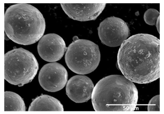
Figure 1.
SEM micrograph of AlSi7Mg powder.
2.2. Sample Fabrication
In the present work, the Renishaw AM 400 system equipped with a Nd:YAG with a power capacity of 400V was used for fabricating parts. The build chamber is filled with argon to ensure that the chamber is free of oxygen during the process. Figure 2a shows vertically oriented thin wall specimens printed with design thicknesses of 0.1 mm, 0.2 mm, 0.3 mm, 0.4 mm, 0.5 mm, 0.6 mm, 0.7 mm, and 0.8 mm. Figure 2b sketches the individual thin wall specimen dimensions. The dimensions (width and thickness) of all thin wall specimens were measured with a Mitutoyo micrometer. The length of the specimens was measured with conventional calipers. For all the measurements, three repetitions were performed to assess the error, and average values were considered for the calculation.
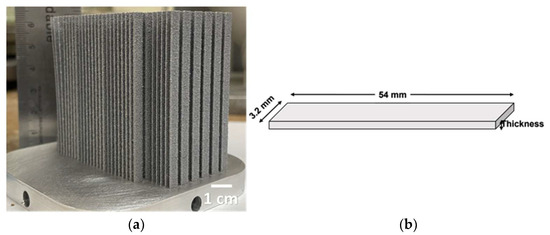
Figure 2.
(a) LPBF-fabricated AlSi7Mg thin walls; (b) Dimensions of individual thin wall specimen.
2.3. Heat Treatment
Three heat treatment schedules were tested. The first set was tested in an as-built (AB) condition. The second set underwent stress relieved annealing (SRA), i.e., 300 °C for 2 h and air-cooled [13]. The third set underwent T5 heat treatment (T5), i.e., 170 °C for 4 h and air-cooled [14].
2.4. Microscopy
A Keyence VHX5000 optical microscope was used to image the cross-section of the parts. The fabricated samples were sectioned, ground, and polished to measure the optical density. Microstructure imaging after etching of the polished sample was performed using a Hitachi SU3500 scanning electron microscope.
2.5. Alternate Cyclic Bend Fatigue Tester
Alternate cyclic bending fatigue testing is a method developed and modified from the flex bending fatigue tester in accordance with ASTM E796 [15]. Figure 3 shows that the test specimen is positioned horizontally, and the midpoint was sandwiched between the mandrels. The sample was subjected to cyclic flexural strains by the alternative movement of the mandrel at 60 cycles/min. The strain was applied in fully reversed condition (i.e., R = −1). The test is carried out until a full fracture is observed. The number of cycles is then registered.
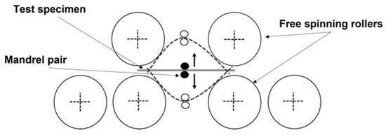
Figure 3.
Alternate cyclic bend fatigue tester.
3. Results & Discussion
3.1. Thin Wall GD&T
Figure 4 shows the mismatch in wall thickness between the as-fabricated and designed models. The percentage of deviation from the designed and as-fabricated decreases from 0.1 mm to 0.8 mm in thin wall thickness. The deviation in wall thickness is created due to the larger melt pool size compared to the hatch distance. This difference is increased for thin wall sections with a small number of hatches [16]. The partially melted powder particles adhere to the surface of thin walls, contributing to surface roughness and features [17]. The error bar associated with design wall thickness shows the minimum deviation for a thickness of 0.1 mm with a gradual increase in designed thickness. This variation could be attributed to features and artifact measurements on the thin wall.
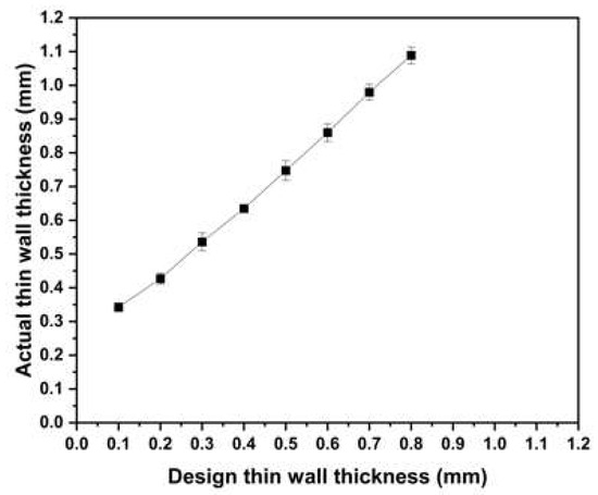
Figure 4.
Graph of the relationship between the designed thin wall thickness to the actual measured thickness.
3.2. Optical Density and Microstructure
Optical micrographs were processed to study the optical density and defects present in the AB samples. For the design thin wall thicknesses from 0.1 mm to 0.8 mm, the optical density of AB specimens was measured to be from 99.4% to 99.9%. The results suggest that as the thickness of thin wall increases, the optical density increases.
Figure 5a shows the SEM microstructure of the AB components as per the XZ plane composed of α-Al cells. The structure tends to elongate along the building direction towards the molten pool center. The cell wall boundaries are rich in Si, a phenomenon occurring due to the low partition coefficient of Si in Al during solidification. This phenomenon has led to extremely fine and closely packed eutectic Si particles surrounding the sub-cell boundaries to form a eutectic Si network [13]. Small micropores are also observed.
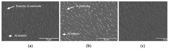
Figure 5.
SEM micrograph of the thin wall specimen (a) as-built (AB); (b) stress-relieved annealing (SRA) at 300 °C for 2 h; (c) T5 heat treatment (T5) at 170 °C for 4 h.
Figure 5b shows the micrograph of SRA microstructure observed on the XZ plane of a sample. After SRA, a change in microstructure was observed. The eutectic Si networks, which are continuous in AB conditions, have disintegrated and broken. Moreover, the Si eutectic phases and Si eutectic network containing phases within the cell walls also coarsened due to Ostwald ripening [18]. Silicon spheroidization occurs upon disintegration of the Si crystals, due to solid-state atomic self- and/or inter-diffusion, which is a time- and temperature-dependent phenomenon [19]. Figure 5c depicts the microstructure after the T5 heat treatment. Cheng et al. [14] reported that the eutectic Si wall thickness of the specimen remains similar to that of the AB condition. No coarsening into larger Si precipitates or dissociation of the Si-network was observed at T5 [14]. Zhen et al. [18] performed TEM studies on T5 heat treatment of the F357 alloy; the strengthening phase contains Si-rich clusters.
3.3. Alternate Cyclic Bending Fatigue Test in ELCF Regime
Figure 6 shows the plot of delta strain vs. number of cycles to failure for AlSi7Mg for the different wall thicknesses for AB, SRA, and T5 heat treatment conditions using an alternate cyclic bend fatigue test. It is observed that all tested thin wall specimens in different conditions failed within less than 100 number of cycles, which comes under the ELCF regime. As the delta strain decreases, the number of cycles to failure increases. As the design thin wall thickness increases from 0.1 mm to 0.8 mm, the number of cycles to failure decreases for AB and SRA conditions. However, there are no noticeable changes in the T5 condition.
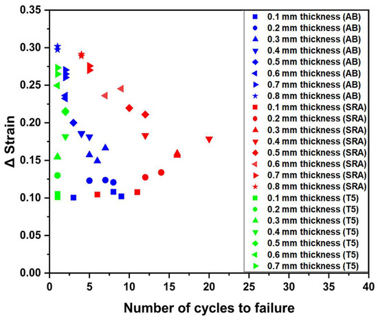
Figure 6.
Δ strain vs. number of cycles to failure tested with alternate cyclic bend fatigue tester in ELCF regime for AlSi7Mg thin wall specimens.
On comparing AB and SRA thin wall specimens tested for a specific thickness range, it can be observed that SRA thin wall specimens can sustain almost double the number of cycles to failure compared to AB. This could be attributed to the difference in the microstructure. As the eutectic Si network in AB condition was broken down into coarser Si particles in SRA conditions, Ostwald ripening is known to promote ductility. This leads to an improvement in plasticity and better fatigue life compared to AB. However, T5 heat-treated thin wall specimens show a lower number of cycles to failure compared to AB thin wall specimens, which could attribute to the strengthening of matrix caused by Si-rich cluster and Si-rich precipitates, which lead to decreased ductility and poor fatigue performance for a design thin wall thickness ranging from 0.1 mm to 0.8 mm. Moreover, the microstructure of T5 shows no difference in SEM compared to the microstructure of AB.
4. Conclusions
This study used thin wall specimens of different thicknesses under various heat treatment conditions to investigate the number of cycles to failure after subjecting them to alternate cyclic bend fatigue test methodology in the ELCF regime. The following conclusions can be drawn:
- The alternate cyclic bend fatigue test for thin wall specimens fabricated from LPBF AlSi7Mg alloy specimens was developed and examined.
- For AB and SRA conditions tested in an alternate cyclic bend fatigue tester, as the delta strain decreases with a decrease in thin wall thickness, the number of cycles to failure increases.
- Thin wall fatigue specimens tested with SRA condition take a greater number of cycles to failure and show better cyclic bending fatigue behavior compared to those in AB and T5 conditions.
Author Contributions
M.K.: Conceptualization, Investigation, Formal analysis, Data curation, Writing—Original Draft Preparation, Writing—Review and Editing. R.M.G.: Investigation. S.P.: Investigation. M.B.: Conceptualization, Resources, Supervision, Project administration, Funding Acquisition, Writing—Review and Editing. All authors have read and agreed to the published version of the manuscript.
Funding
This research received financial support from the Natural Sciences and Engineering Research Council of Canada (NSERC: project number: NETGP 494158–16).
Institutional Review Board Statement
Not applicable.
Informed Consent Statement
Not applicable.
Data Availability Statement
The author does not have permission to share data.
Acknowledgments
The author would like to thank Richard Chromik for providing access to ZYGO 3D optical surface profilometer and would like to extend thanks to Angelica Ivonne Valencia Ruiz for the help with the printing of the F357 aluminum alloy specimens.
Conflicts of Interest
The authors declare no conflict of interest.
References
- Siddique, S.; Imran, M.; Rauer, M.; Kaloudis, M.; Wycisk, E.; Emmelmann, C.; Walther, F. Computed tomography for characterization of fatigue performance of selective laser melted parts. Mater. Des. 2015, 83, 661–669. [Google Scholar] [CrossRef]
- Siddique, S.; Awd, M.; Tenkamp, J.; Walther, F. High and very high cycle fatigue failure mechanisms in selective laser melted aluminum alloys. J. Mater. Res. 2017, 32, 4296–4304. [Google Scholar] [CrossRef]
- Khoda, B.; Ahsan, A.M.M.N.; Shovon, A.N.; Alam, A.I. 3D metal lattice structure manufacturing with continuous rods. Sci. Rep. 2021, 11, 434. [Google Scholar] [CrossRef] [PubMed]
- Alexopoulos, N.D.; Pantelakis, S.G. Quality evaluation of A357 cast aluminum alloy specimens subjected to different artificial aging treatment. Mater. Des. 2004, 25, 419–430. [Google Scholar] [CrossRef]
- Kimura, T.; Nakamoto, T. Microstructures and mechanical properties of A356 (AlSi7Mg0.3) aluminum alloy fabricated by selective laser melting. Mater. Des. 2016, 89, 1294–1301. [Google Scholar] [CrossRef]
- Miranda, G.; Faria, S.; Bartolomeu, F.; Pinto, E.; Alves, N.; Peixinho, N.; Gasik, M.; Silva, F. A study on the production of thin-walled Ti6Al4V parts by selective laser melting. J. Manuf. Process. 2019, 39, 346–355. [Google Scholar] [CrossRef]
- Morciano, M.; Alberghini, M.; Fasano, M.; Almiento, M.; Calignano, F.; Manfredi, D.; Asinari, P.; Chiavazzo, E. 3D printed lattice metal structures for enhanced heat transfer in latent heat storage systems. J. Energy Storage 2023, 65, 107350. [Google Scholar] [CrossRef]
- Zhang, Y.; Majeed, A.; Muzamil, M.; Lv, J.; Peng, T.; Patel, V. Investigation for macro mechanical behavior explicitly for thin-walled parts of AlSi10Mg alloy using selective laser melting technique. J. Manuf. Process. 2021, 66, 269–280. [Google Scholar] [CrossRef]
- Majeed, A.; Muzamil, M.; Khan, M.A.; Malik, E.H.; Huzaifa, M.; Lv, J.; Dar, N.U. Comprehensive Mechanical Behavior of Thin-Walled Additively-Manufactured Parts of AlSi10Mg by SLM in As-Built, Post-Solution, and Aging Treatment Conditions. JOM 2023, 75, 3067–3082. [Google Scholar] [CrossRef]
- Kim, Y.; Hwang, W. High-Cycle, Low-Cycle, Extremely Low-Cycle Fatigue and Monotonic Fracture Behaviors of Low-Carbon Steel and Its Welded Joint. Materials 2019, 12, 4111. [Google Scholar] [CrossRef] [PubMed]
- Kanvinde, A.M.; Deierlein, G.G. Cyclic Void Growth Model to Assess Ductile Fracture initiation in structural steels due to ultra low cycle fatigue. J. Eng. Mech. 2007, 133, 6. [Google Scholar] [CrossRef]
- Yonekura, D.; Arai, Y.; Komotori, J.; Shimizu, M. Fracture Mechanism of Ferritic Ductile Cast Iron in Extremely Low Cycle Fatigue. Trans. Jpn. Soc. Mech. Eng. Ser. A 1999, 65, 821–826. [Google Scholar] [CrossRef][Green Version]
- Wang, M.; Song, B.; Wei, Q.; Zhang, Y.; Shi, Y. Effects of annealing on the microstructure and mechanical properties of selective laser melted AlSi7Mg alloy. Mater. Sci. Eng. A 2019, 739, 463–472. [Google Scholar] [CrossRef]
- Cheng, C.C.; Li, Z.; Dhillon, J.S.; Hudon, P.; Brochu, M. Influence of powder layer thickness on microstructure and T5 heat treatability of F357 alloy fabricated by laser powder bed fusion process. J. Alloys Compd. 2023, 948, 169633. [Google Scholar] [CrossRef]
- ASTM E796-94; Standard Test Method for Ductility Testing Ofmetallic Foil, (reapproved 2000). ASTM International: West Conshohocken, PA, USA, 2000; pp. 1–4.
- Lam, T.-N.; Lee, A.; Chiu, Y.-R.; Kuo, H.-F.; Kawasaki, T.; Harjo, S.; Jain, J.; Lee, S.Y.; Huang, E.-W. Estimating fine melt pool, coarse melt pool, and heat affected zone effects on the strengths of additive manufactured AlSi10Mg alloys. Mater. Sci. Eng. A 2022, 856, 143961. [Google Scholar] [CrossRef]
- Grimm, T.; Wiora, G.; Witt, G. Characterization of typical surface effects in additive manufacturing with confocal microscopy. Surf. Topogr. Metrol. Prop. 2015, 3, 014001. [Google Scholar] [CrossRef]
- Li, Z.; Cheng, C.C.; Dhillon, J.S.; Kwon, S.Y.; Hudon, P.; Brochu, M. Precipitation behavior of an Al7SiMg alloy processed by laser powder bed fusion during non-isothermal and isothermal heat treatments. Materialia 2023, 28, 101751. [Google Scholar] [CrossRef]
- Alghamdi, F.; Song, X.; Hadadzadeh, A.; Shalchi-Amirkhiz, B.; Mohammadi, M.; Haghshenas, M. Post heat treatment of additive manufactured AlSi10Mg: On silicon morphology, texture and small-scale properties. Mater. Sci. Eng. A 2020, 783, 139296. [Google Scholar] [CrossRef]


Disclaimer/Publisher’s Note: The statements, opinions and data contained in all publications are solely those of the individual author(s) and contributor(s) and not of MDPI and/or the editor(s). MDPI and/or the editor(s) disclaim responsibility for any injury to people or property resulting from any ideas, methods, instructions or products referred to in the content. |
© 2023 by the authors. Licensee MDPI, Basel, Switzerland. This article is an open access article distributed under the terms and conditions of the Creative Commons Attribution (CC BY) license (https://creativecommons.org/licenses/by/4.0/).