Abstract
Structure from the geometry and analysis of the three-spherical kinematic chain-base parallel mechanism have been studied. The parallel mechanism evolved from an origami fold as chain legs with three spherical kinematic chains becoming rigid bodies. The parallel mechanism with a three 6R kinematic chain as three chain legs is complicated. The reconfiguration of the parallel mechanism with full tilt–circle movement, kinematic, and workspace are investigated, too. This parallel mechanism can be applied in specific applications with certain treatments.
1. Introduction
The parallel mechanism is the system that converts the motions of several bodies into constrained motions of other bodies [1]. The parallel mechanism has a closed-loop as a type of mechanism [1], and that is made of an end-effector (mobile platform) [2] and a fixed platform, linked together by independent kinematic chains [1]. Furthermore, structure, workspace considerations, singularities, and link interference need to be considered in the design [2]. The parallel mechanism has much potential in several fields, including industrial, space, medical science, and miscellaneous applications [2].
Origami is Japanese cultural art, which is the art of folding paper. In general, origami starts with flat paper (2D object), then folds become a 3D object with various shapes and forms without stretching, cutting, or gluing [3]. Moreover, origami has become an inspiration for engineers in various fields. Especially waterbomb-base origami has become an inspiration in engineering for several applications. Fonseca and Savi [3] presented an investigation of the origami waterbomb-base pattern from its unit cell and explored the different formulations for origami structure. Liang, Gao, Huang, and Li [4] presented the design of a pneumatic rigid–flexible coupling origami gripper from a waterbomb-base origami pattern. Salerno, Zhang, Menciassi, and Dai [5] proposed the concept of a miniaturized surgical tool grasper as a 3-DOF parallel module inspired by the waterbomb-base origami.
It is common to see the creases of origami mechanisms as the compliant mechanism joint with flexible material. However, the origami mechanism becomes rigid if the creases are replaced with non-flexible material. One of the rigid kinematic origami models describes the creases with the revolute joint mechanism [6].
2. Geometry of Parallel Mechanism
A parallel mechanism consists of a base, a platform, and legs to sustain the platform. The leg structure is obtained from waterbomb-base origami, which involves the spherical kinematic chain with a close loop structure. The parallel mechanism consists of three legs and one actuator in the middle of the mechanism.
2.1. Waterbomb-Base Origami for Spherical Mechanisms
As shown in Figure 1a,b, origami starts with flat paper and then folds to become creases. The creases consist of two types. The first type has a convex shape called Mountain creases, denoted by M, and the second type has a concave shape called Valley creases, represented by V [7,8].
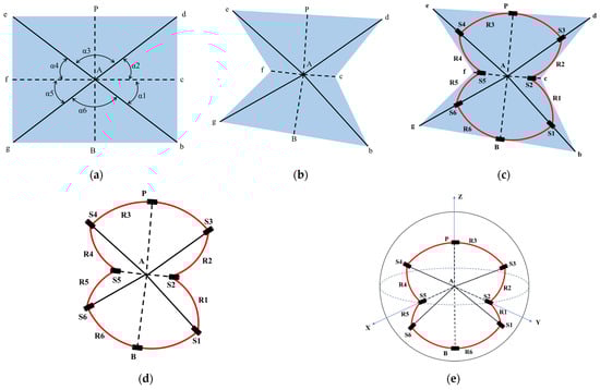
Figure 1.
Waterbomb-base origami involves a spherical mechanism. (a) origami starts with flat paper; (b) origami starts fold become a crease; (c) the creases and the planes on the waterbomb-base structure; (d) the figure mapping the spherical mechanism from the origami evolved; (e) the spherical mechanism.
Waterbomb-base origami consists of six planes and six creases. Of the six creases, Ac and Af are the valley-crease types, and Ab, Ad, Ae, and Ag are the mountain-crease types. As shown in Figure 1c, the creases and the planes on the waterbomb-base structure are represented for the revolute pairs and the links, respectively [7]. Thus, the waterbomb-base origami form contains six revolute pairs and six links. Barreto et al. [8] made an analogy between the spherical mechanism and the origami vertex as a concept of mechanism design.
Maekawa’s-Justin’s Theorem [9] is as follows. Let M be the number of mountain creases and V be the number of valley creases adjacent to a vertex in a flat origami crease pattern. Then, M − V = ±2. Moreover, Kawasaki–Justin’s Theorem [9] lets v be a vertex of degree 2n is an origami crease pattern and be the consecutive angles between the creases. Then, the creases adjacent to v (locally) fold flat only if
That is, the two theorems correspond with waterbomb-base origami form. As shown in Figure 1d,e, the figure mapping and the spherical mechanism from the origami evolve. In the waterbomb base origami, Point A is the intersection of the whole of the connected creases, while in the spherical mechanism, point A is the virtual point intersection of the axis from the whole revolute pair in the spherical kinematic chain. The revolute pair and links are denoted with S and R, respectively. The link is deformed by revolute joints and . Due to this close loop structure, link forms by revolute joint and . and have a revolute joint for connecting mobile and base platforms. Link has the angle . The relationship between the angles in waterbomb-base origami is ; meanwhile, .
The initial shape of waterbomb-base origami can be a square () or a rectangular (), depending on the intended use, application, and other parameters. Determining it requires further discussion.
2.2. Parallel Mechanism
The parallel structure mechanism consists of a mobile platform, a fixed platform, three legs, and a truss in the middle of the mechanism. Meanwhile, the legs are represented by the spherical kinematic chain involved in waterbomb-base origami, and then, the structure has three spherical kinematic chains for the legs [7]. The truss consists of a prismatic connector hinge and two offset universal hinges to connect to the mobile platform and base platform. The truss component has supported the movement of the mobile platform concerning the base platform.
Figure 2 shows the revolute pair and the link , where is the number of legs and is the number of a revolute pair. P and B are the revolute joints paired with the mobile and base platforms.
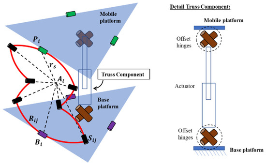
Figure 2.
Structure of parallel mechanism.
3. Kinematic of Structure Mechanism
In this section, the displacement analysis of the parallel mechanism is presented. This parallel mechanism establishes global reference and local reference. Point Ob–XYZ is established as the global reference frame at the base platform. The X-axis and the Y-axis are perpendicular and parallel to the axis of the revolute hinge with the center point , respectively. At the same time, the Z-axis is normal to the base following the right-hand rule [7]. In addition, the mobile platform has a point Op-XYZ as the midpoint, and the legs and the truss component have the local reference frame. Table 1 explains the procedure of the DH Convention for knowing the forward kinematics [10].

Table 1.
Table of Procedure based on DH Convention.
The table presents the DH parameter determined by four transformation parameters [10] from the link and joint parameters [11]. Link parameters are the length of the link () and the angle of a twist of a link (); meanwhile, joint parameters as the offset of link () and joint angle () represent the relative positions of the following links [11].
In Ref. [10],
- = distance from the intersection of the , and -axis to point are measured along ;
- = angle from to is measured about .
- = distance from to the intersection of the and -axis are measured along . If joint i is prismatic, is variable.
- = angle from to , and is measured about . If joint i is revolute, i is variable.
3.1. Leg
In Ref. [3], the waterbomb chain is related to a close chain, and the last revolute joint pairs with the first revolute joint. Therefore, waterbomb chain does not have an end effector. In this regard, evaluating the close loop equation is necessary, rather than considering the end-effector [3].
3.2. Truss Parallel Mechanism
The truss component section consists of a prismatic hinge connector, and two offset universal hinges connect to the mobile platform and the base platform. Figure 2 shows the detail of the truss component. Point and point are the center of the hinge axe connected to the mobile platform and the base platform, respectively. Point and point are the centers of the two universal hinge axes. At the same time, point and point are directly connected to the prismatic hinge [12]. l represents the prismatic hinge length, the distance between the center point and point . Each hinge axe variable has the offset distance between the center of the local coordinate hinge axe. The distance between point Ob and point Op represents the height of the mechanism (h).
Table 1 shows the procedure of the DH convention. As shown in Figure 3, the axis of each joint is already available, which corresponds from step 1 to step 7. Table 2 shows the Denavit–Hartenberg (DH) parameters [13] of the truss component for each link.
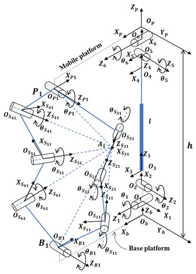
Figure 3.
Kinematic model with global coordinate frame and local coordinate frame.
Table 2.
Denavit–Hartenberg (DH) parameter of the truss component.
According to step 8 in Table 1, substituting Equation (3) obtains the form of the homogeneous transformation matrices.
Equation (5) gives the position and orientation of the mobile platform with respect base platform, as shown in Figure 4.
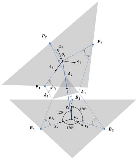
Figure 4.
Schematic of the parallel mechanism.
4. Motion Characteristics of a Structure Mechanism
In this structure, the truss component is active, and the legs are passive. Therefore, the active component moves as the structure drives, while the passive component limits the driven movement.
4.1. Rotation around X-axis
Figure 5 shows the rotation around the X-axis of the global coordinate frame in the base platform. The rotation happens due to the rotation of the -axis. The rotation of the -axis determines the orientation of the end effector. The revolute hinge rotates clockwise or counterclockwise. Activating the prismatic hinge adjusts the radius of the structure’s rotation. The minimum and maximum radii are the prismatic hinge’s minimum and maximum strokes, respectively.
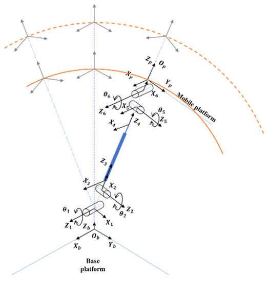
Figure 5.
Rotation around the X-axis.
4.2. Rotation around Y-axis
Figure 6 shows the rotation around the Y-axis of the global coordinate frame in the base platform. The rotation happens due to the rotation of the -axis. The rotation of the -axis determines the orientation of the end effector. The revolute hinge rotates clockwise or counterclockwise. Activating the prismatic hinge adjusts the radius of the structure’s rotation. The minimum and maximum radii are the prismatic hinge’s minimum and maximum strokes, respectively.
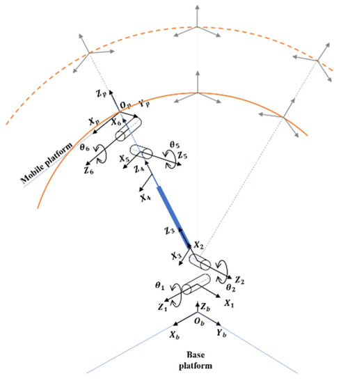
Figure 6.
Rotation about the Y-axis.
4.3. Translation along X-axis
Figure 7 shows the translation along the X-axis of the global coordinate frame in the base platform. The translation movement activates the combination of two rotations and a prismatic hinge. Meanwhile, the rotations occur on the -axis and the -axis. The translational moving away depends on the stroke of a prismatic hinge. Furthermore, the angle degree of the -axis is the same as with the -axis in the opposite direction. Thus, the rotation on the revolute hinge can rotate clockwise or counter-clockwise.
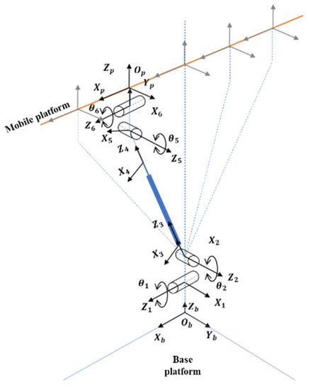
Figure 7.
Translation along the X-axis.
4.4. Translation along Y-axis
Figure 8 shows the translation along the Y-axis of the global coordinate frame in the base platform. The translation movement activates the combination of two rotations and a prismatic hinge. Meanwhile, the rotation happens on the -axis and the -axis. The translational moving away depends on the stroke of a prismatic hinge. Moreover, the angle degree of the -axis is the same as with the -axis in the opposite direction. Thus, the revolute hinge rotates clockwise or counterclockwise.
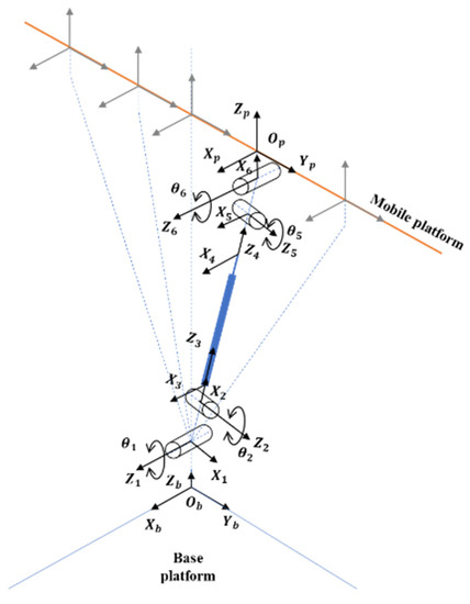
Figure 8.
Translation along the Y-axis.
4.5. Translation along Z-axis
Figure 9 shows the translation along the Z-axis of the global coordinate frame in the base platform. The translation movement only activates a prismatic hinge. The high of the structure’s parallel mechanism depends on the stroke of the prismatic joint.
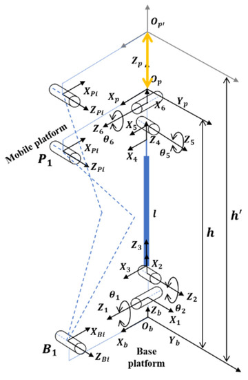
Figure 9.
Translation along the Z-axis.
4.6. Rotation with Tilt Movement
As shown in Figure 10, there is a combination of the structure movement parallel mechanism. The mechanism shows a tilt with moving around. All motors can be active and need control, depending on the requirements.
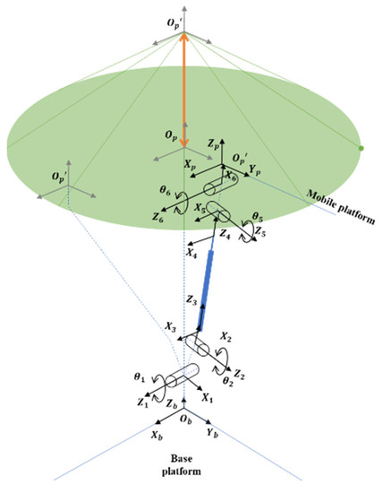
Figure 10.
Rotation with tilt movement.
5. Conclusions
The parallel structure mechanism consists of a mobile platform, a fixed platform, three legs, and a truss in the middle of the mechanism. Point Ob–XYZ is established as the global reference frame at the base platform. Movement of the structure to the Ob–XYZ is observed in the base platform. There are six motion characteristics of the structure mechanism.
Author Contributions
Conceptualization, S.-C.H.; methodology, L.A.M. and S.-C.H.; software, L.A.M.; validation, S.-C.H.; formal analysis, L.A.M.; investigation, S.-C.H.; writing—original draft preparation, L.A.M.; writing—review and editing, S.-C.H.; project administration, S.-C.H. All authors have read and agreed to the published version of the manuscript.
Funding
This research received no external funding.
Institutional Review Board Statement
Not applicable.
Informed Consent Statement
Not applicable.
Data Availability Statement
Not applicable.
Acknowledgments
The authors acknowledge and thank the Ministry of Science and Technology of the Republic of China for their partial financial support of this study under Contract Number MOST 111-2221-E-992-068.
Conflicts of Interest
The authors declare no conflict of interest.
References
- Liu, X.; Wang, J. Classification of Parallel Mechanisms. In Parallel Kinematics; Springer: Berlin/Heidelberg, Germany, 2014; pp. 3–29. [Google Scholar]
- Patel, Y.D.; George, P.M. Parallel Manipulators Applications—A Survey. Mod. Mech. Eng. 2012, 2, 57–64. [Google Scholar] [CrossRef]
- Fonseca, L.M.; Savi, M.A. On the symmetries of the origami waterbomb pattern: Kinematics and mechanical investigations. Meccanica 2021, 56, 2575–2598. [Google Scholar] [CrossRef]
- Liang, D.; Gao, Y.; Huang, H.; Li, B. Design of a Rigid-Flexible Coupling Origami Gripper. In Proceedings of the 2021 IEEE International Conference on Robotics and Biomimetics (ROBIO), Sanya, China, 27–31 December 2021; pp. 1283–1287. [Google Scholar] [CrossRef]
- Salerno, M.; Zhang, K.; Menciassi, A.; Dai, J.S. A Novel 4-DOF Origami Grasper with an SMA-Actuation System for Minimally Invasive Surgery. IEEE Trans. Robot. 2016, 32, 484–498. [Google Scholar] [CrossRef]
- Bowen, L.A. A Study of Action Origami as Systems of Spherical Mechanisms. Ph.D. Thesis, Brigham Young University, Provo, UT, USA, 2013. [Google Scholar]
- Zhang, K.; Fang, Y.; Fang, H.; Dai, J. Geometry and Constraint Analysis of the Three-Spherical Kinematic Chain Based Parallel Mechanism. J. Mech. Robot. 2010, 2, 031014. [Google Scholar] [CrossRef]
- Barreto, R.L.P.; Morlin, F.V.; Souza, M.B.D.; Carboni, A.P.; Martins, D. Multiloop origami inspired spherical mechanisms. Mech. Mach. Theory 2021, 155, 104063. [Google Scholar] [CrossRef]
- Hull, T. Counting Mountain-Valley Assignments for Flat Folds. Ars Comb. 2003, 67, 175–188. [Google Scholar]
- Spong, M.W.; Hutchinson, S.; Vidyasagar, M. Robot Modeling and Control; John Wiley & Sons: Hoboken, NJ, USA, 2006. [Google Scholar]
- Pratihar, D.K. Fundamentals of Robotics: Manipulators, Wheeled and Legged Robots; Alpha Science International Ltd.: Oxford, UK, 2017. [Google Scholar]
- Zhang, Y.; Han, H.; Zhang, H.; Xu, Z.; Xiong, Y.; Han, K.; Li, Y. Acceleration analysis of 6-RR-RP-RR parallel manipulator with offset hinges by means of a hybrid method. Mech. Mach. Theory 2022, 169, 104661. [Google Scholar] [CrossRef]
- Denavit, J.; Hartenberg, R.S. A Kinematic Notation for Lower-Pair Mechanisms Based on Matrices. ASME J. Appl. Mech. 1955, 22, 215–221. [Google Scholar] [CrossRef]


Disclaimer/Publisher’s Note: The statements, opinions and data contained in all publications are solely those of the individual author(s) and contributor(s) and not of MDPI and/or the editor(s). MDPI and/or the editor(s) disclaim responsibility for any injury to people or property resulting from any ideas, methods, instructions or products referred to in the content. |
© 2023 by the authors. Licensee MDPI, Basel, Switzerland. This article is an open access article distributed under the terms and conditions of the Creative Commons Attribution (CC BY) license (https://creativecommons.org/licenses/by/4.0/).