Abstract
As a joining-by-forming process, clinching and the use of functional elements enable low-energy joining of components through form, force, and, under certain conditions, material closure. In addition to the transmission of mechanical forces, these joining processes can be qualified for additional electrical contact within the scope of functional integration for electro-mobile applications. For this purpose, maximizing the force and material closure is necessary to ensure a long-term, stable transmission of electrical currents. To this end, the electrical properties of the joints were optimized. The investigations carried out show the long-term behavior under normal operating conditions and the short-circuit case.
1. Introduction
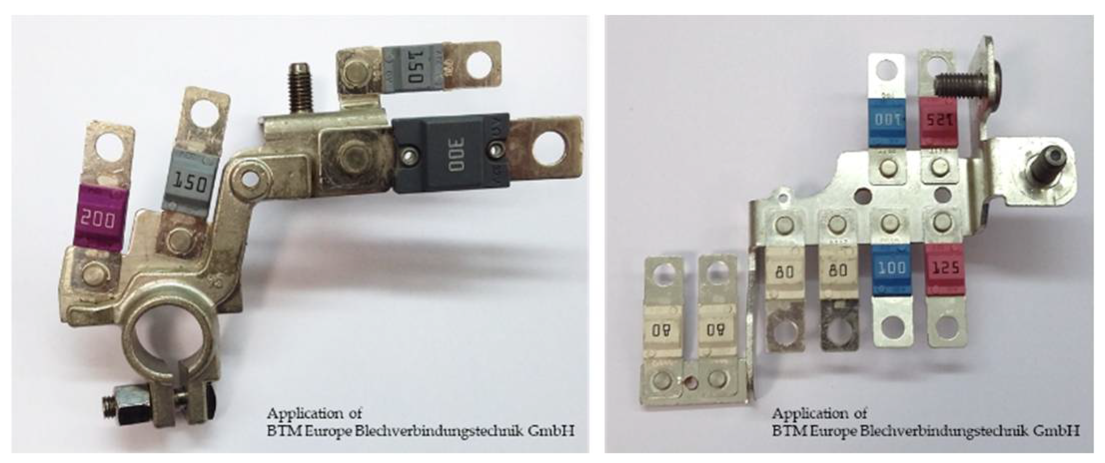
Weight reduction through lightweight construction is an essential approach to meeting the growing demand for a reduction in energy consumption, and not only in automotive engineering. The technical task of joining materials together in a way that is both mechanically load-bearing and electrically conductive places new demands on joining technology. This functional integration is required, for example, in the field of increasing electrification in the automobile in the areas of driving, energy storage [1], and fuses (Figure 1), where the process-safe joining of thermally sensitive electrical or electronic components must be ensured.
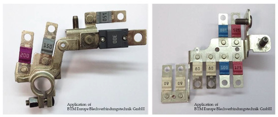
Figure 1.
Clinched joints and functional elements in electrical applications.
As a joining-by-forming process, clinching [2] and the use of functional elements [3] for sheet-like semi-finished parts offer many possibilities for the implementation of lightweight design approaches [4]. For example, clinching can be used to join sheets of different thicknesses [5] and materials [6]. When clinching is used to mechanically join two or more components, the state of the art is to dimension the clinched joint on the base of the characteristic geometric variables of neck thickness and undercut [2]. A basic overview for further characterization of clinched aluminum joints is provided by Kupfer in [7].
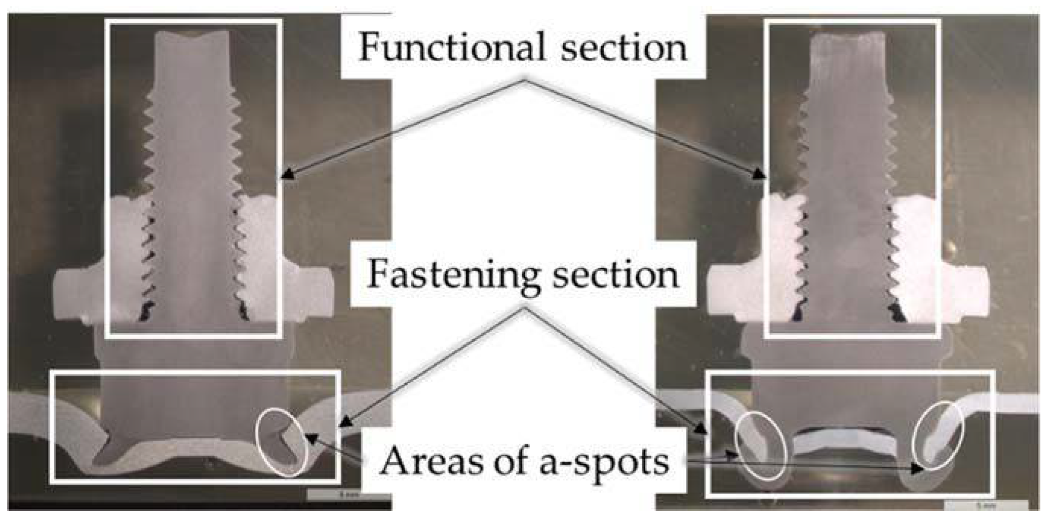
In addition to the bolting of thin semi-finished products, functional elements also enable one-sided accessibility [8] during assembly. For this reason, and due to the low energy requirements in the manufacture of the joints, these joining processes are extremely cost-effective. Previous work on functional elements has dealt with basic characteristic value determinations about mechanical applications [9]. Furthermore, Wanner [10] carried out investigations of these elements with a focus on the stress limits for functional element bolted joints. In [11], Denkert dealt with the design and assembly of threaded supports inserted into sheet metal by forming technology. The range of applications for mechanically set functional elements is wide, such as for purely mechanical applications, e.g., for fastening clinched bus bars (Figure 1), or for electrical applications, e.g., for grounding without carrying significant continuous currents, for which self-piercing bolts are used. Furthermore, functional elements can also be used for coated and thermally sensitive materials or surfaces. Functional elements have, on the one hand, a fastening section with which the elements and the base component are joined and, on the other hand, a functional section which, depending on the intended use, can be designed, for example, as a threaded carrier (Figure 2).
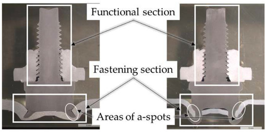
Figure 2.
Functional elements of self-piercing threaded bolts.
The functional elements can be divided into three groups. These groups differ in the shape of the fastening section and in the way they are joined to the base component. A distinction is made between press-fit and rivet-fit elements, which require a pre-punching operation in the base component, and self-piercing elements, which do not require a pre-punching operation. An overview of these and other distinguishing features is presented and discussed in [12]. The fastening section is of decisive importance for the use of functional elements for electrical contacting since this area functions for contacting with the base component. Self-piercing elements, which cut into the base component to be contacted through their fastening section and generate a form-closure and force-closure component as a result of the deformation that occurs, are advantageous for this application. As a result of the cutting, the fastening section of the functional element is brought into contact with the juvenile base material of the base component, which leads to metallic micro-contacts (also named a-spots) due to a system-inherent relative movement between the fastening section and the base component.
The forming joining processes of clinching and the use of self-piercing elements generate bare metallic interfaces between the joining partners due to the processes inherent in the system during the joining process, such as surface enlargement and relative movement. From an electrical point of view, the metallic interfaces always represent a closed contact, and it is necessary to know the electrical properties of these joints to be able to use them specifically for electrical contact. Joining-by-forming processes are primarily based on the form- and force-closure types [13], which ensure the mechanical properties of the joints. Under certain conditions, the material-closure type can occur [14], which characterizes the electrical properties in addition to the force-closure component. By adapting the binding mechanisms in the form of the closure types to the respective application, stable and safe current transport can be achieved in the long term, with simultaneous mechanical protection of the fragile a-spots [3]. If functional extensions of clinched joints and functional elements are required, e.g., as electrical contact, a pure design by neck thickness and undercut is no longer sufficient. In this case, the binding mechanisms, which are characterized by the form-, force-, and material-closure components, must be taken into account to create and characterize the a-spots required for electrical contact, according to Holm [15].
When electrical currents are transmitted through clinched joints and functional elements, the interfaces between the joining partners can represent barriers in the current flow. These can lead to an increased temperature at the joint, resulting in the aging of the electrical contacts. When using formed joints for contacting electrical conductors, the currently known aging mechanisms of force reduction, inter-diffusion, electro-migration, frictional wear, and chemical reactions must be taken into account, depending on the contact material and the load that occurs, according to [16,17]. All aging mechanisms are temperature-dependent and lead to an increase in joint resistance. Depending on the load current and the environmental conditions, one or more mechanisms may dominate the aging. Particularly in thermally stressed aluminum joints, stress relaxation due to high joint temperatures can have a decisive influence on aging, leading to a reduction in the force-closure component and then to oxidation processes in the a-spots (micro contacts). The force-closure component can decrease within a short time due to creep processes in the conductor and terminal materials (here of the fastener) and the joint resistances increase concerning the initial values after assembly [18]. In the literature, the reduction in the contact force due to stress relaxation in bolted current joints is described by [19] and in clinched joints in [3,20].
To quantify the aging influences on the long-term behavior of current-carrying joints described here, the following investigations were carried out on clinched joints and self-piercing threaded bolts.
2. Materials and Methods
2.1. Materials
The material basis for the tests carried out was the aluminum alloy AlMg0.8Si0.9 (AA6181). The bus bars had a thickness of 2.0 mm for the clinch joints and a thickness of 1.2 mm for use with the self-piercing studs. This aluminum was tested with various surface and heat treatment states, as currently used in automotive construction. The aluminum material was used in the T4 heat treatment condition (solution annealed + work-hardened) and had an EDT (electro-discharge texturing) surface on the one hand and passivation on the other. During the passivation process, the non-uniform oxide layer of the Al surface was removed and replaced by a defined thin and durable conversion layer. After the joining process, the specimens were transferred to the T6 condition by precipitation hardening at 185 °C for 20 min.
The steel test samples DC04+ZE75/0 with a thickness of 1.2 mm used here were cold-rolled deep-drawing steel electrolytic galvanized on one side and were tested with the self-piercing studs. These deep-drawing steels represent a typical steel grade used in automotive production.
2.2. Methods
2.2.1. Measurement of the Electrical Joint Resistance
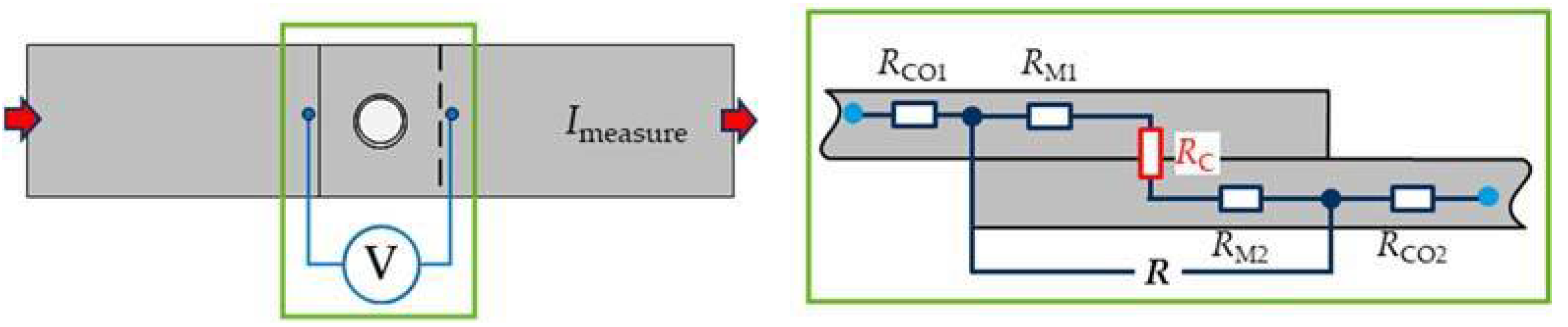
The electrical resistances of the joints were measured with the four-wire measurement method (Kelvin method) described in [2,21]. Here, a direct current (Imeasure) was injected into the joint, and the voltage drop U between two defined points was measured. On the clinched specimens, the resistance across the joint was determined between the potential measurement points (Figure 3). The measured electrical resistance R consists of the material resistance (RM) of the individual joining partners and the contact resistance RC. RCO represents the resistance of the homogeneous current-carrying conductors (Figure 2).
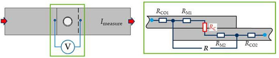
Figure 3.
Measuring principle for determining the resistance of clinched joints [3].
The self-piercing studs used here were integrated directly into the current path. The current must flow through the functional element after contact. In this application, the functional element closes the circuit for the operation of an electrical consumer, e.g., via the vehicle body (grounding). Two potential measuring points (R1 and R2) were defined on the sheet metal for the self-piercing studs (Figure 4). With the potential measuring point at the “currentless” end for R2 of the bus bar, the proportion of material resistance (RM) can be minimized and thus the contact resistance (RC) can be determined accurately.
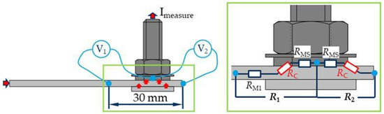
Figure 4.
Measuring principle for determining the resistance of joints with the self-piercing stud [3].
2.2.2. Test Conditions of the Performed Examinations
In the first step, the electrical quality of the joints after joining and precipitation hardening, i.e., the contact behavior, was considered. Subsequently, the electrical behavior of the joints under thermal and electrical–thermal load was investigated. The joints were first subjected to thermal stress in a heating cabinet for a period of 1000 h. Under these test conditions, a constant temperature occurs in the joint and in the homogeneous current-carrying conductor. The joint resistance was measured cyclically. Subsequently, the tests on compounds with the lowest resistance and the smallest change in resistance were continued in current-carrying tests for at least 4000 h. Under these test conditions, temperature unevenness can occur depending on the quality of the electrical contact in the joint and in the homogeneous current-carrying conductor. For example, a higher temperature occurs in the joint if the electrical resistance is significantly higher than the electrical resistance of the current-carrying homogeneous conductors. The results of these tests were used to determine the resistance of the compounds.
3. Results
3.1. Clinching
The investigated clinched joints that had a nominal diameter of 8 mm were joined using split dies (Figure 5). For a detailed process flow, please refer to [2]. Methods for determining the properties of such joints are presented in more detail in [7]. Two variants (Series C1 and C2) were selected.
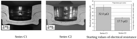
Figure 5.
Cross-section of investigated clinch joints and electrical joint resistance.
The two series differ in terms of their primary application. Series C1 is optimized for mechanical properties, whereas Series C2 is designed for electrical applications. This difference in electrical properties is illustrated in Figure 5 by comparing the electrical resistances. On the C1 series specimens for the mechanically optimized version, average resistances of R = 32.0 μΩ were measured after clinching. After electrical optimization of this clinch joint by increasing the punch diameter and simultaneously increasing the base thickness [3], the average joint resistance was reduced to R = 17.5 μΩ (Figure 5). The initial values of the electric joint resistances are not always sufficient for a prediction of long-term behavior. The performance factor ku is a helpful parameter for this purpose. This evaluates the quality of the joint (Equation (1)).
ku = R/RCO
The performance factor is therefore used for subsequent long-term studies. A performance factor of 1 indicates that the same power loss is generated in the joint as in the homogeneous conductor [22].
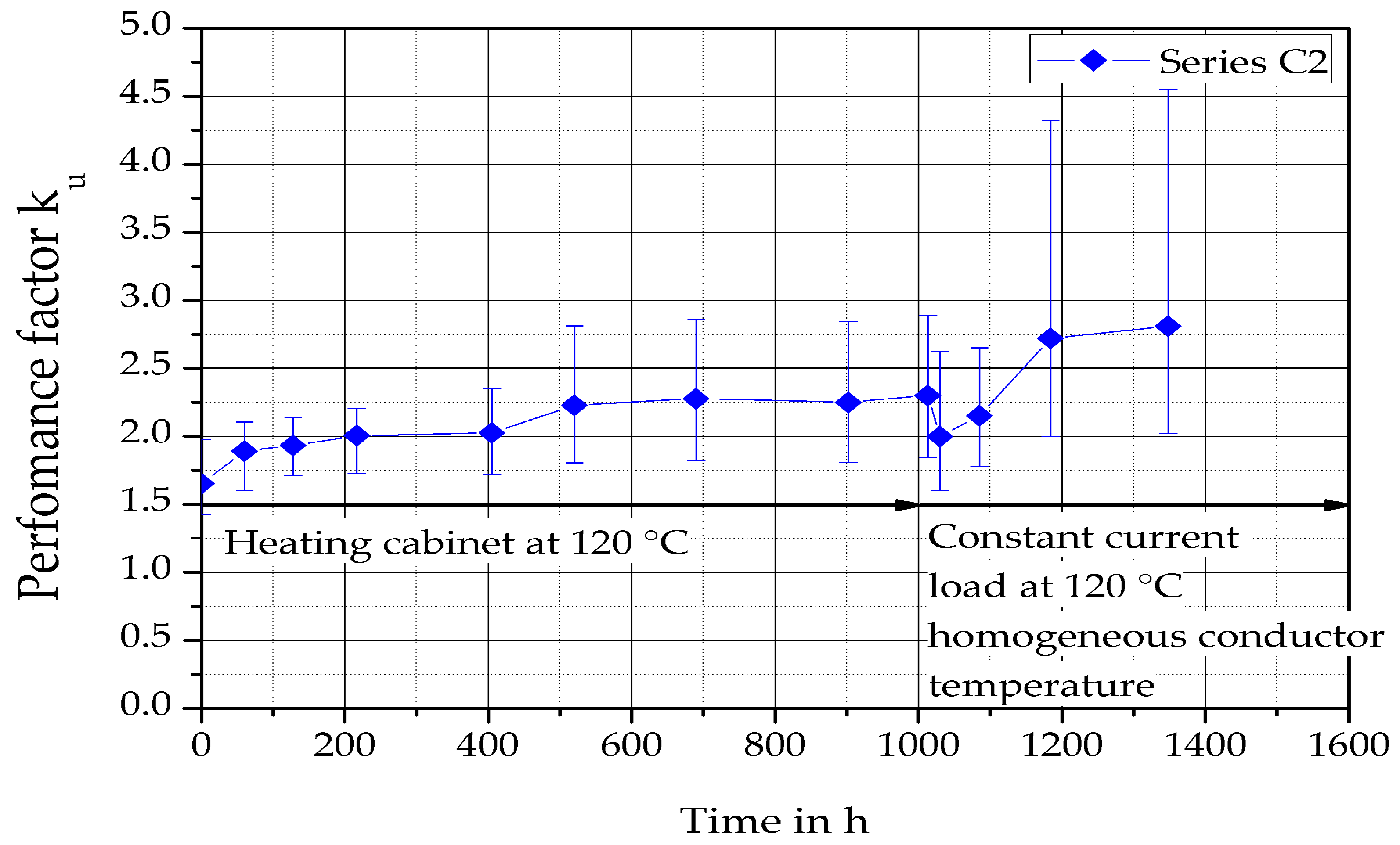
The long-term behavior of the clinched aluminum compounds is shown in Figure 6. It can be seen that the performance factor of the clinched joints increases from ku = 1.65 after precipitation hardening during the forming phase to ku = 2.3 in the first 1000 h. At this thermal load in the heating cabinet, the temperature of the joint and the homogeneous conductor are the same. During the subsequent energization of the joints, the performance factor continues to increase up to ku = 2.81 with a simultaneous increase in the tolerance band.
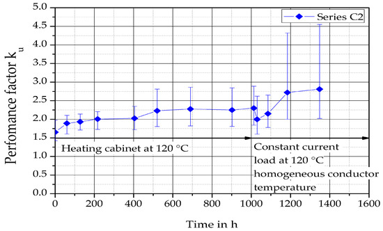
Figure 6.
Performance factor ku of clinch joints depending on the time in accordance with [3].
3.2. Functional Elements
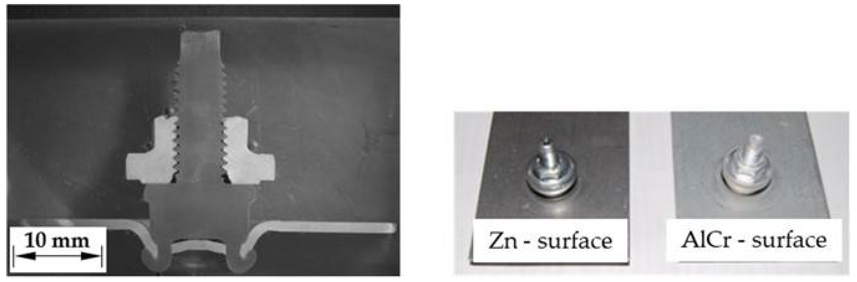
In the investigations carried out, galvanized self-piercing studs were initially used. Self-piercing studs were selected for the investigations on the functional elements. With these joining elements, a pre-punching operation is not necessary and the joining process of the element in the sheet metal can be automated. During the joining process, the fastening section of the functional element first cuts completely through the bus bar material. During the subsequent forming of the fastening section by a die, a form-closure- and force-closure-based joint are produced on the underside of the joined part (Figure 7).
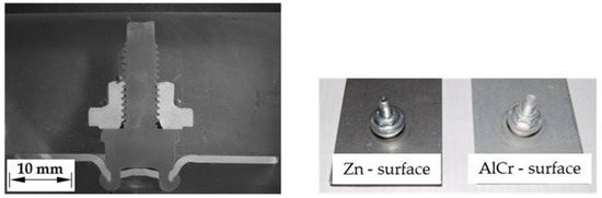
Figure 7.
Cross-section and surface conditions of the self-piercing studs [20].
The stud elements were used with a metric thread of dimension M6 (Figure 7), and an overview of the tests performed is given in Table 1.

Table 1.
Overview of self-piercing studs.
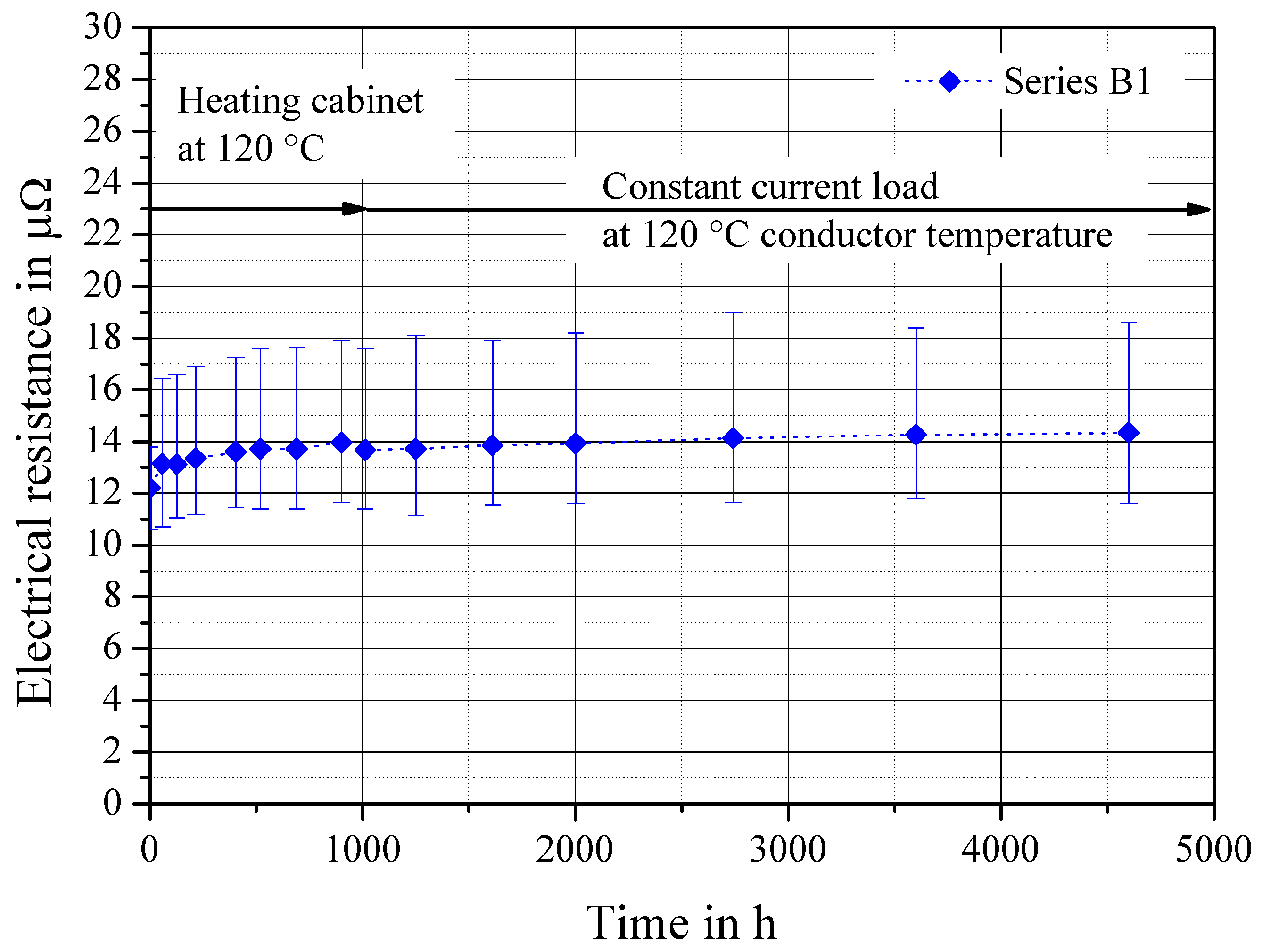
The long-term behavior of Series B1 under a thermal load of 120 °C for 1000 h (formation phase) in the heating cabinet shows only very slight resistance changes for joints with self-piercing studs with a galvanized surface and sheets made of DC04+ZE75/0 (Figure 8). Under a thermal load caused by an electric current (140 A) which a temperature in the homogeneous conductor also of 120 °C establishes, the samples were applied for a further 4000 h. The measured values shown were determined at measuring position R2, so the influence of the material resistance is minimized. Long-term stable operation, e.g., for grounding, is possible for an operating temperature of 120 °C.
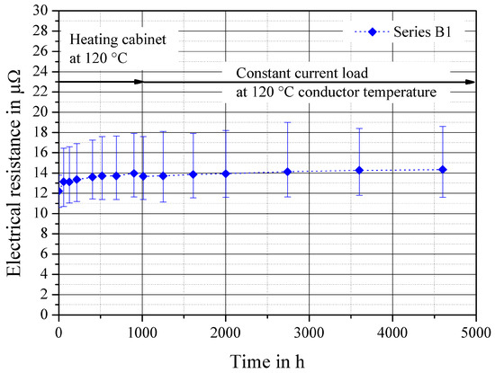
Figure 8.
Electrical resistance (R2) depends on the time in a heating cabinet at 120 °C (continuous load) and constant current load at 120 °C conductor temperature in accordance with [20].
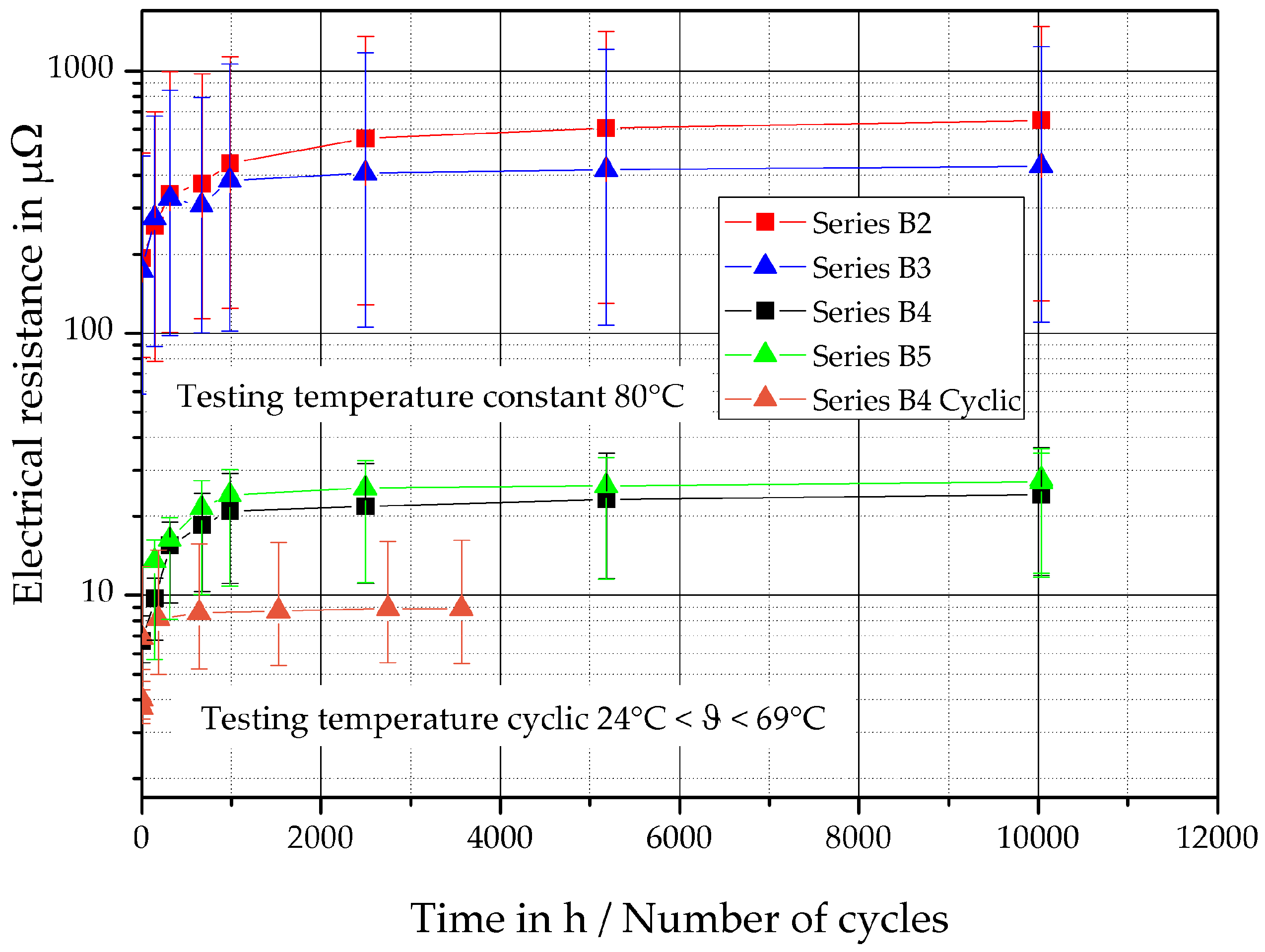
When these functional elements are used in aluminum materials, e.g., ground bolts in aluminum body parts or as current-carrying contacts, the different thermal expansion coefficients between the steel bolt and the aluminum components must be considered in addition to the types of closure that occur. These different thermal expansion coefficients lead under a thermal load due to the resistive heating to a change in the percentage of the force–closure component between the bolt element and the aluminum conductor. A reduction in the force-closure component can lead to an increase in the electrical resistance and thus to a reduced current-carrying capacity. To improve the current-carrying capacity with simultaneous corrosion protection, an alternative surface layer for the self-piercing stud was investigated. This was an Al-Cr coating applied by the PVD process. In [23], this surface layer was developed and applied to joining elements (semi-tubular self-piercing rivets and blind rivets). This surface layer was already the subject of investigations in [24] to improve corrosion protection. After joining, the electrical resistances were measured according to Figure 4. In an evaluation of the measured electrical resistance, it can be observed that the series with the galvanized element surface have initial values of R01 = 193.6 μΩ for series B2 and R01 = 173.9 μΩ for series B3. For the series with the aluminized surfaces B4 and B5, significantly reduced electrical resistances were measured (Series B4 R01 = 6.71 μΩ and Series B5 R01 = 13.56 μΩ). In addition to the reduction in the electrical resistances, the scatter bands within the individual series were also drastically reduced by the aluminized surface (Figure 9). This allows judgements that are more reliable regarding the electrical conductivity against the background of process reliability. After this initial measurement, precipitation hardening of the specimens was carried out at 185 °C for 20 min. After that, a thermal loading in the heating cabinet at a constant temperature of 80 °C was realized to characterize the long-time behavior. The resistance increased at the studs with the AlCr coating from an average value of 13.6 μΩ (EDT) and 6.7 μΩ (passivated) to 27.8 μΩ (EDT) and 24.3 μΩ (passivated) after assembly during the formation phase (after 1000 h) of long-term tests (Figure 9).
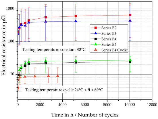
Figure 9.
Electrical resistance (RV1) depends on the time in a heating cabinet at 80 °C (continuous load) and cyclic load.
The average resistance and the scattering band increase significantly more after the formation phase for the galvanized punching studs. After the same time at continuous load, the resistance of the joints between the aluminum bus bars and galvanized punching pins was 600 μΩ, a factor of 25 higher than that of the joints with aluminized piercing studs (Figure 9). In subsequent alternating load tests, only the aluminized piercing studs (Series B4) were examined, which exhibited the lowest aging effect under constant thermal load. The selected B4 series was tested under the current load. A current of 80 A was fed into the test circuit in such a way that a temperature of 69 °C was reached at the joints.
When the temperature was achieved, the current was switched off and the joints were actively cooled down to room temperature. One cycle lasted approx. 60 min. The temperature at the joints was determined and recorded. The behavior was comparable to the tests under constant load. The resistance increased from an average value of 9.9 μΩ to 12 μΩ after assembly in the formation phase and did not change significantly after 3566 load cycles (Figure 9).
4. Discussion
In the evaluation of the investigations carried out, it can be stated that the strain hardening introduced by the forming process during clinching is reduced by recovery and probably local recrystallization because of the loading temperature [3]. This reduces the mechanical stress in the contact area, which leads to a reduction in the force-closure component between the joining partners and influences the stability of the a-spots. The limit operating temperature of these clinch joints is determined by the aluminum material and its homologous temperature, as well as the degree of deformation introduced. The limit operating temperature also changes as soon as these parameters (material, degree of deformation) change. When using the aluminum materials investigated here, the long-term behavior can be improved by reducing the degree of deformation when designing the clinch joints or by reducing the currents to be transmitted, which reduces the heating at the joint. The investigations on the functional elements were carried out on galvanized self-piercing studs. To improve the current-carrying capacity with simultaneous corrosion protection, an aluminized surface layer was investigated. The alternating layer structure, starting with a Cr layer and ending with an Al layer, offers the possibility of creating metallic a-spots between similar conductor materials through the relative movement inherent in the system during the joining process between the component surface and the aluminized surface of the self-piercing stud. A visual comparison of the boundary layers in the area of the fastening section is shown in Figure 10. Figure 10a indicates the preparation location.
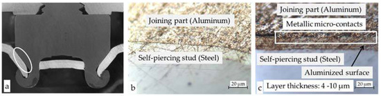
Figure 10.
Metallographic cross-section of the fastening section (a), of surface layers at self-piercing studs with zinc coating (b) and Al-Cr coating at the self-piercing stud (c) [20].
In Figure 10b, a clear boundary can be seen. There, the electrical contact is based on the present force-closure component. In the picture in Figure 10c, a metallic a-spot can be seen. During the joining process of the self-piercing stud, a contact surface not contaminated with foreign layers is created when the bus bar plane is cut through. The additional relative movement between the contact partners leads to the breakup of impurity layers, in particular oxide layers on the surface of the bus bar, and a-spots arise [20]. In addition to the form- and force-closure components, there is also a material-closure component, which ensures the significantly reduced electrical resistance and the stable electrical long-term behavior of the self-piercing stud made of steel with the aluminized surface in aluminum bus bars.
Author Contributions
Conceptualization, J.K. and S.S.; methodology, U.F.; validation, J.K., S.S., and G.R.; formal analysis, U.F.; investigation, J.K., S.S. and G.R.; writing—original draft preparation, J.K.; writing—review and editing, U.F. and S.S.; visualization, J.K. and G.R.; supervision, U.F.; project administration, U.F.; funding acquisition, U.F. All authors have read and agreed to the published version of the manuscript.
Funding
This research was funded by the Deutsche Forschungsgemeinschaft (DFG, German Re- search Foundation)—TRR 285—Project-ID 418701707, subproject A04, and the IGF Project (AiF 16952BR) of the European Research Association for Sheet Metal Working was supported via AiF within the program for promoting the Industrial Collective Research (IGF) of the German Ministry of Economic Affairs and Climate Action (BMWK), based on a decision by the German Bundestag.
Institutional Review Board Statement
Not applicable.
Informed Consent Statement
Not applicable.
Data Availability Statement
The recorded data can be found in ref. [3]. The data have been reprocessed with respect to the binding mechanisms such as shape closure, force closure and material closure.
Conflicts of Interest
The authors declare no conflict of interest.
References
- Zwicker, M.; Moghadam, M.; Zhang, W.; Nielsen, C.V. Automotive battery pack manufacturing—A review of battery to tab joining. J. Adv. Join. Process. 2020, 1, 100017. [Google Scholar] [CrossRef]
- Meschut, G.; Merklein, M.; Brosius, A.; Drummer, D.; Fratini, L.; Füssel, U.; Gude, M.; Homberg, W.; Martins, P.; Bobbert, M.; et al. Review on mechanical joining by plastic deformation. J. Adv. Join. Process. 2022, 5, 100113. [Google Scholar] [CrossRef]
- Füssel, U.; Großmann, S.; Kalich, J.; Schlegel, S.; Ramonat, A. Optimierung umformtechnischer Fügeverfahren zur Kontaktierung Elektrischer Leiter; European Research Association for Sheet Metal Working: Hannover, Germany, 2019; ISBN 978-3-86776-559-6. [Google Scholar]
- Lee, C.-J.; Kim, J.-Y.; Lee, S.-K.; Ko, D.-C.; Kim, B.-M. Parametric study on mechanical clinching process for joining aluminum alloy and high-strength steel sheets. J. Mech. Sci. Technol. 2010, 24, 123–126. [Google Scholar] [CrossRef]
- Mucha, J.; Kaščák, L.; Spišák, E. Joining the car-body sheets using clinching process with various thickness and mechanical property arrangements. Arch. Civ. Mech. Eng. 2011, 11, 135–148. [Google Scholar] [CrossRef]
- Eshtayeh, M.M.; Hrairi, M.; Mohiuddin, A.K.M. Clinching process for joining dissimilar materials: State of the art. Int. J. Adv. Manuf. Technol. 2016, 82, 179–195. [Google Scholar] [CrossRef]
- Kupfer, R.; Köhler, D.; Römisch, D.; Wituschek, S.; Ewenz, L.; Kalich, J.; Weiß, D.; Sadeghian, B.; Busch, M.; Krüger, J.; et al. Clinching of Aluminum Materials—Methods for the Continuous Characterization of Process, Microstructure and Properties. J. Adv. Join. Process. 2022, 5, 100108. [Google Scholar] [CrossRef]
- Füssel, U.; Liebrecht, F. Untersuchung der Verbindungscharakteristik von Funktionselementen im verschraubten Zustand; European Research Association for Sheet Metal Working: Hannover, Germany, 2011; ISBN 978-3-86776-362-2. [Google Scholar]
- Hahn, O.; Jendrny, J.; Voelkner, W.; Timm, M. Kennwertermittlung an Selbststanzenden Funktionselementen Sowie Niet-, Einpreßmuttern Und -bolzen: Ergebnisse Eines Vorhabens der Industriellen Gemeinschaftsforschung (IGF); EFB: Hannover, Germany, 1999; ISBN 9783867761406. [Google Scholar]
- Wanner, M.-C.; Denkert, C.; Füssel, U.; Süße, D. Beanspruchungsgrenzen für Funktionselement-Verschraubungen: Ergebnisse eines Forschungsvorhabens der industriellen Gemeinschaftsforschung (IGF); EFB-Forschungsbericht EFB-427: Hannover, Germany, 2015. [Google Scholar]
- Denkert, C. Bemessung und Montage umformtechnisch ins Blech eingebrachter Gewindeträger. Ph.D. Dissertation, Universität Rostock, Rostock, Germany, 2020. [Google Scholar]
- European Aluminium Association. The Aluminium Automotive Manual—Joining; European Aluminium Association: Woluwe-Saint-Pierre, Belgium, 2015. [Google Scholar]
- Groche, P.; Wohletz, S.; Brenneis, M.; Pabst, C.; Resch, F. Joining by forming—A review on joint mechanisms, applications and future trends. J. Mater. Process. Technol. 2014, 214, 1972–1994. [Google Scholar] [CrossRef]
- Riedel, F. Eigenschaftsverbesserung von Durchsetzfügeverbindungen Durch Die Kombination mit Stoffschluss; Shaker Verlag GmbH: Düren, Germany, 1997. [Google Scholar]
- Holm, R. Electric Contacts: Theory and Applications; Reprint of the Fourth Completely Rewritten ed. 1967, 3rd Printing 2000; Springer: Berlin/Heidelberg, Germany, 2000; ISBN 9783540038757. [Google Scholar]
- Braunovic, M.; Konchits, V.V.; Myshkin, N.K. Electrical Contacts; CRC Press: Boca Raton, FL, USA, 2017; ISBN 9781315222196. [Google Scholar]
- Pfeifer, S.; Großmann, S.; Freudenberger, R.; Willing, H.; Kappl, H. Characterization of Intermetallic Compounds in Al-Cu- Bimetallic Interfaces. In 2012 IEEE 58th Holm Conference on Electrical Contacts (Holm 2012), Portland, Oregon, USA, 23–26 September 2012; IEEE: Piscataway, NJ, USA, 2012; pp. 1–6. ISBN 978-1-4673-0781-9. [Google Scholar]
- Kindersberger, J.; Löbl, H.; Schoft, S. Plastic Deformation and Loss of Joint Force by Creep in High Current Joints. In Proceedings of the 20th International Conference on Electrical Contacts, Stockholm, Sweden, 19–23 June 2000. [Google Scholar]
- Braunovic, M. Effect of Different Types of Mechanical-Contact Devices on the Performance of Bolted Aluminium-to-Aluminium Joints under Current Cycling and Stress Relaxation Conditions. In Proceedings of the 32th IEEE Holm-Conference on Electrical Contacts, Boston, MA, USA, 27–29 October 1986. [Google Scholar]
- Füssel, U.; Großmann, S.; Kalich, J.; Schlegel, S.; Schmid, J. Elektrisches Eigenschaftsprofil umformtechnischer Fügeverbindungen; European Research Association for Sheet Metal Working: Hannover, Germany, 2014; ISBN 978-3-86776-432-2. [Google Scholar]
- Kalich, J.; Füssel, U. Influence of the Production Process on the Binding Mechanism of Clinched Aluminum Steel Mixed Compounds. JMMP 2021, 5, 105. [Google Scholar] [CrossRef]
- Böhme, H. Mittelspannungstechnik: Schaltanlagen Berechnen und Entwerfen, 2., Stark Bearb. Aufl.; Huss-Medien Verl. Technik: Berlin, Germany, 2005; ISBN 3341014950. [Google Scholar]
- Kirchhoff, V.; Fietzke, F. Entwicklung und Bewertung von PVD-Schichtsystemen auf Verbindungselementen zur Verbesserung der Alterungsbeständigkeit von Nietverbindungen; European Research Association for Sheet Metal Working: Hannover, Germany, 2012; ISBN 978-3-86776-385-1. [Google Scholar]
- Schütz, A.; Gehrke, J. Qualifikation von Belastungs- und Prüfverfahren für die Verwendung in kombinierten Ermüdungsalgorithmen; European Research Association for Sheet Metal Working: Hannover, Germany, 2012; ISBN 978-3-86776-387-5. [Google Scholar]


Publisher’s Note: MDPI stays neutral with regard to jurisdictional claims in published maps and institutional affiliations. |
© 2022 by the authors. Licensee MDPI, Basel, Switzerland. This article is an open access article distributed under the terms and conditions of the Creative Commons Attribution (CC BY) license (https://creativecommons.org/licenses/by/4.0/).