Abstract
This study consists of a modern and economic way to recover the heat wasted from the industrial chimneys which are cooled down by natural sources by using thermal electric generator heat sinks. A flap with altered heat sink (which is attached at the top of thermo-electric generator) is used in place of convectional heat sink base. A 3D model is proposed by using AUTODESK Fusion 360 and is solved by using Workbench 2021 R1 ANSYS. The presented setup fully describes the transfer of heat along the one vertical bar inside the TEGs module which is mounted along the vertical wall of the Chimney. The impact of Flap dimensions (Height, Depth, and Angle) and conductive material performance is studied. The flap angles are 45°, 50° and 60° and depths of the flap are 28 mm, 30 mm and 33 mm. This altered heat sink accomplishes about 28% enhance in the rate of cooling of TEGs module. The maximum output power, i.e., 105 mV of the TEGs module is at 60° and at 33 mm depth. The results show that remodified heat sink maintains the system simple and requires less maintenance and also improves the cooling rate of the thermoelectric generator, which as a result improves its performance and make it reliable.
1. Introduction
The operation of the TEG is dependent upon Seebeck effect, which is used to generate electrical power generation by applying significant temperature difference over the minimal thickness. Lv et al. [1] suggested different techniques for the finer cooling of the TEGs. Demir and Dincer proposed shell and tube type heat exchanger for the removal of exhaust fumes from the exhaust, while fresh air is used to cool the TEGs module. Maximum production of power from this system is 158 W correlate with the density of power 108.8 W/m2 [2]. Figure 1 shows (a) TEG module domain and its (b) Geometry.
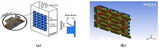
Figure 1.
(a) TEG Module Domain (b) Geometry of TEG.
Only limited research has been carried out on the TEG for recovery of dissipated heat from a smokestack when it subjected to passive cooling. Ansys fluent module is used to solve a 3D CFD model described in this paper. The heat is deviated away from the chimney by employing flaps on the upper side of the heat sink. Flaps are angled at various angles and have varying depths. The 3D model represents all the features of the temperature distribution, directional electric field strength, potential difference, and total heat flow rate. The goal of the study is to recuperate the heat dissipated from the funnel and transfer this wasted heat into electrical power.
2. Methodology
2.1. Physical Domain
Flap used has a specific inclination angles ‘α’ and specific length ‘Lf’ in respect of the upright surface of the chimney. Flap contiguity with heat abstraction thickness of base is 0.5 mm and fins of the heat sink is 2 mm. Number of fins mounted on heat sink is 13, with a height of 30 mm and its thickness is 2 mm, its height from the base of the heat sink is 30.5 mm. The purpose of these modifications in the heat sink is used to increase the heat transfer and cool the TEG’s module mounted on chimney’s vertical surface [3]. A heat spreader has a thickness of 75 × 90 × 0.5 mm is mounted between heat sink vertical surface and wall of chimney. TEG module structure consists of 36 Thermocouples whose positive leg is made up of Bismuth Telluride (BiTe+) and negative leg is (BiTe−) having leg length ‘Lg’ 1.4 mm. Figure 2 shows the TEG schematic diagram.
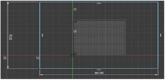
Figure 2.
Schematic diagram of TEG.
2.2. Governing Equations
For solid domain, heat scattering equation is used to govern the rate of heat transfer across (TEG, spreader, and heat sink) [4]. Following equations help to govern flow of fluid and heat transfer which surround the heat absorber [5]. Equations (4)–(6), respectively, represent them [6,7].
2.3. Material Properties
Figure 3 shows Material behavior of positive and negative leg. Material used is Bismuth-Telluride alloy.
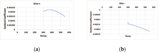
Figure 3.
(a) Material behavior of positive leg (b) Material behavior of negative leg.
Equations (7)–(9) show the See beck coefficient, electrical conductivity, and thermal conductivity for both legs [8,9]. Copper (thermal conductivity 385 W/mK) is used. Atmospheric Air is considered as perfect gas [10].
2.4. Numerical Solving
These governing equations are valid for TEG modules as long material and formation of design do not change [11]. There are considerations of the buoyancy effect in which ambient pressure varies linearly with the change of height Equation (14).
3. Results and Discussion
3.1. Impact of Flap Depth
Figure 4 displays effect of temperature and voltage on depth of flap. The result shows that by using conventional heat sink with TEG module has the lowest output power and has minimum efficiency.
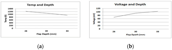
Figure 4.
(a) Impact of Temperature on depth (b) Impact of Voltage on depth.
3.2. By Using Conductive Flap
It is clearly shown from the Figure 5 that as we use flap to enhance the cooling rate of TEG the output voltage also increases.
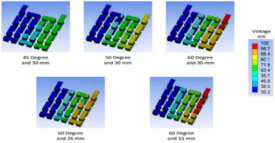
Figure 5.
Variation of voltage at different angle.
At 45 degree the max voltage is 57.8 mV which is 39% more than without flap. At 50 degree the max voltage is 72.5 mV which is 20% more than at 45 degrees. At 60-degree output max voltage is 93.4 mV which is 22% more than that at 50 degrees. Now by increasing flap depth out max voltage also increases.
3.3. Effect of Flap Angle
From above Figure 6 it can be concluded that on smaller angle, TEG voltage is negligible. So, it is concluded that as the tilt angle of flap increases, the output power also enhances. Figure 7 shows variation of voltage on different angled flaps (i.e., 0°, 30°, 50° and 60°).
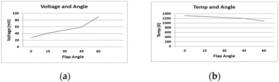
Figure 6.
(a) Effect of voltage on flap angle (b) Effect of temperature on flap angle.
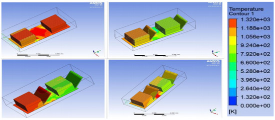
Figure 7.
Variation of voltage on different angled flaps.
4. Conclusions
This study presents numerical investigation to effectively recover waste heat from the industrial sources and produce electricity using thermoelectric generator. The flap angle and the depth of the flap are varied to find the best configuration. Flap of 45°, 50° having depth of 30 mm, 30 mm, respectively, and 60° having depth of 26 mm, 30 mm and 33 mm are used. Flap with angle 600 and having depth 33 mm provides maximum cooling rate 28% and produce voltage 105 mV.
Author Contributions
Conceptualization, A.A. and M.A.Z.; methodology, A.A. and N.M.M.; software, A.A. and N.M.M.; validation, A.A. and N.M.M.; formal analysis, A.A. and M.A.Z.; investigation, A.A. and N.M.M.; data curation, M.A.Z.; writing—original draft preparation, A.A.; writing—review and editing, A.A. and N.M.M.; supervision, A.A.; project administration, A.A. All authors have read and agreed to the published version of the manuscript.
Funding
This research received no external funding.
Institutional Review Board Statement
Not applicable.
Informed Consent Statement
Not applicable.
Data Availability Statement
Not applicable.
Conflicts of Interest
The authors declare no conflict of interest.
References
- Lv, S.; He, W.; Jiang, Q.; Hu, Z.; Liu, X.; Chen, H.; Liu, M. Study of Different Heat Exchange Technologies Influence on the Performance of Thermoelectric Generators. Energy Convers. Manag. 2018, 156, 167–177. [Google Scholar] [CrossRef]
- Demir, M.E.; Dincer, I. Performance Assessment of a Thermoelectric Generator Applied to Exhaust Waste Heat Recovery. Appl. Therm. Eng. 2017, 120, 694–707. [Google Scholar] [CrossRef]
- Yazicioğlu, B.; Yüncü, H. Optimum Fin Spacing of Rectangular Fins on a Vertical Base in Free Convection Heat Transfer. Heat Mass Transfer 2007, 44, 139. [Google Scholar] [CrossRef][Green Version]
- John Wiley & Sons, Ltd. Thermoelectric Generators. In Thermoelectrics: Design and Materials; John Wiley & Sons, Ltd.: Hoboken, NJ, USA, 2016; pp. 8–22. ISBN 9781118848944. [Google Scholar]
- John Wiley & Sons, Ltd. Modeling of Thermoelectric Generators and Coolers with Heat Sinks. In Thermoelectrics: Design and Materials; John Wiley & Sons, Ltd.: Hoboken, NJ, USA, 2016; pp. 99–119. ISBN 9781118848944. [Google Scholar]
- Hassan, H. Heat Transfer of Cu–Water Nanofluid in an Enclosure with a Heat Sink and Discrete Heat Source. Eur. J. Mech. B Fluids 2014, 45, 72–83. [Google Scholar] [CrossRef]
- Eldesoukey, A.; Hassan, H. 3D Model of Thermoelectric Generator (TEG) Case Study: Effect of Flow Regime on the TEG Performance. Energy Convers. Manag. 2019, 180, 231–239. [Google Scholar] [CrossRef]
- Lin, C.-C.; Ginting, D.; Lydia, R.; Lee, M.H.; Rhyee, J.-S. Thermoelectric Properties and Extremely Low Lattice Thermal Conductivity in P-Type Bismuth Tellurides by Pb-Doping and PbTe Precipitation. J. Alloys Compd. 2016, 671, 538–544. [Google Scholar] [CrossRef]
- Yim, J.-H.; Jung, K.; Yoo, M.-J.; Park, H.-H.; Kim, J.-S.; Park, C. Preparation and Thermoelectric Properties of Quaternary Bismuth Telluride–Indium Selenide Compound. Curr. Appl. Phys. 2011, 11, S46–S49. [Google Scholar] [CrossRef]
- Çengel Yunus, A.; Ghajar, A.J. Heat and Mass Transfer: Fundamentals & Applications, 4th ed.; McGraw-Hill: New York, NY, USA, 2011. [Google Scholar]
- Klaus, H. Jet Engines: Fundamentals of Theory, Design and Operation; The Crowood Press: Marlborough, UK, 2010. [Google Scholar]


Publisher’s Note: MDPI stays neutral with regard to jurisdictional claims in published maps and institutional affiliations. |
© 2022 by the authors. Licensee MDPI, Basel, Switzerland. This article is an open access article distributed under the terms and conditions of the Creative Commons Attribution (CC BY) license (https://creativecommons.org/licenses/by/4.0/).