Abstract
The key objective of the research is to calculate and design the Small Horizontal Axis Wind Turbine (HAWT) that can meet Pakistan’s energy needs. This is the plan for producing approximately 20 kW of electricity to distribute the load used by common household appliances. This study will focus on Jamshoro, Sindh, Pakistan, where a wind turbine is considered to generate electricity. The appropriate design is required to make the turbine more efficient and decreases the cost. Q-blade wind turbine software verifies the design parameters. The maximum power factor is achieved at the design speed of 8 m/s. Design analysis is also performed in Q-blade wind turbine simulation software.
1. Introduction
Pakistan is among the ten countries in the world facing the most serious energy crisis. As the country faces challenges with numerous monetary, political, and social issues, the conversion from a traditional fill-based economy to a green economy will be difficult. The household consumes 30% of the total energy generated and electricity demand is increasing daily and posing a challenge to the current energy solution. In urban areas, the energy demand increases more as people migrate from the big city [1].
In the old days, the energy produced from the wind was used for many purposes as the grinding of wheat and corn. However, “Blade Element Momentum Theory” was introduced during the 1980s. Using this theory, many wind turbine designs were presented [2]. The energy demand in the world is increasing continuously, and 2% of this demand is increasing through fossil fuel, which has terrible and adverse effects on our environment [3]. Until 2009, not a single network of wind farms existed. However, presently, the circumstance has changed remarkably, and wind ranches adding to the general framework are now a reality [4,5]. Presently, the current administration of Pakistan has introduced an arrangement for a power age up to 2030 that assumes an introduced capacity in the north of 162 GW [6]. In the south (Sindh and Baluchistan), Pakistan has a 1046 km coastline, although most wind power projects are now being built in the GharoKeti Bander and Hyderabad wind corridors. Calculating the axial and circumferential inducible factors of wind turbine wings is challenging. The geometry of the blades is very complex; additionally, the blades are now manufactured with glass fiber and carbon fiber composite layer structures for high wind turbine performance [7,8].
The purpose of the research is to calculate and design a small wind turbine for small-scale energy needs in Pakistan. This is the plan for generating about 20 kW of electrical energy to spread the load used by common household machines. The area for this study is Jamshoro, Sindh province, Pakistan, the place where wind turbines will be built to generate power. Wind power design formulations are used to estimate the blade design values. At a designed velocity of 8 m/s, a reliable energy coefficient is obtained.
2. Design Parameters
The following parameters mentioned in Table 1 are analyzed and considered for the blade design.

Table 1.
Design Parameters.
3. Results and Discussion
The direction of the wind is one of the wind aspects. The location of a wind farm and the placement of wind turbines inside the wind farm are heavily reliant on statistical information about wind directions over time. Upwind wind turbines reduce wind speed and increase disturbance for downwind wind turbines. The wind’s power is directly proportional to the cubic of mean wind speed (v).
Output Power is the electric power supplied by the generator [9].
The value of CP (Power Coefficient) decreases as wind speed increases. Equation (3) shows the relation between CP and wind speed.
The tangential speed at the tip of the blade is divided by the actual wind speed to calculate TSR. Its value determines by using Equation (4). Tip speed ratios concerning different wind speeds relation is shown in Table 2 at different wind speeds.
Table 2.
Output power.
Actual output can be determined by Equation (2).
4. Airfoil
Airfoils for wind turbines (HAWTs) are often designed with high-lift coefficients and low-drag coefficients for use at small angles of attack. S1020 airfoil | Ornithopter airfoil is used in this research because it gives a reliable lift-to-drag ratio which will be useful to stabilize the wind turbine. Figure 1 shows the shape of the S1020 airfoil.
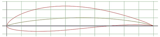
Figure 1.
Airfoil design.
4.1. Foil Specifications
As it increases, the value of the Alpha (Angle of Attack) ratio of lift coefficient to drag coefficient starts decreasing. In real-life, Alpha is between 10 to 15 degrees [10]. In this research, values of Lift to Drag ratio are analyzed for different Angles of Attack between to degrees; it gives very smooth values to 12 degrees. Figure 2a,b show the specification of the airfoil S1020 at 12 degrees and the graph between Alpha and Cl/Cd.
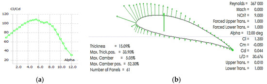
Figure 2.
Alpha (Angle of Attack) and ratio of lift coefficient to drag coefficient.
4.2. Static Structural Analysis
Static Structural Analysis analyzes the effect of stable (or stationary) loading states on a body, while inertia and the damping effects induced by time variable loads are neglected. In this research, the Wind turbine blade is fixed at a circular foil end which is a boundary condition. Figure 3 simulates the Static Structural Analysis for the turbine.
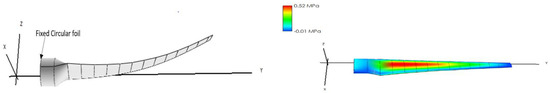
Figure 3.
Static Structural Analysis.
4.3. Airflow Analysis
Airflow analysis is conducted using Q-blade software and analyzed at 8 m/s since using equation (2) approximately 20 kW of electricity can be achieved, theoretically. The colors on the blades show stress on the blades during airflow. By using software, calculated values can be observed experimentally. The calculations are practically testified by using Q-blade wind turbine software at 8 m/s, HWAT generates more than 20 kW of electricity. The airflow analysis and output calculations as described in Figure 4.
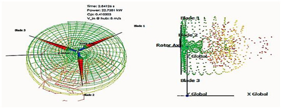
Figure 4.
Airflow Analysis of the wind turbine blade.
5. Conclusions
This study demonstrates the precise design and calculation of 20 kW horizontal axis wind turbines to meet Pakistan’s energy demands—on a small scale. The power factor can be deduced from the current design and calculation. It varies slightly according to wind speed, and its value rises at low wind speeds compared to high wind speeds. In addition, airflow analysis is conducted using Q-blade software at 8 m/s. Hence, the proposed design is suitable to provide pollution-free and sustainable energy.
Author Contributions
Conceptualization, M.H. and S.A.; methodology, M.H.; software A.A.; validation, S.A., A.A. and Z.A.; formal analysis, Z.A. All authors have read and agreed to the published version of the manuscript.
Funding
This research received no external funding.
Informed Consent Statement
Not applicable.
Data Availability Statement
Not applicable.
Acknowledgments
The authors are thankful to UET Lahore, Pakistan for providing the opportunity to finish this research work.
Conflicts of Interest
The authors declare no conflict of interest.
References
- Chougule, P.; Nielsen, S. Overview and Design of Self-Acting Pitch Control Mechanism for Vertical Axis Wind Turbine Using Multi-Body Simulation Approach. J. Phys. Conf. Ser. 2014, 524, 012055. [Google Scholar] [CrossRef]
- Khan, S.; Shah, K.; Izhar-Ul-Haq; Khan, H.; Ali, S.; Ahmad, N.; Abid, M.; Ali, H.; Ihsanullah; Sher, M. Observation of the Starting and Low Speed Behavior of Small Horizontal Axis Wind Turbine. J. Wind Energy 2014, 2014, 527198. [Google Scholar] [CrossRef]
- Porté-Agel, F.; Bastankhah, M.; Shamsoddin, S. Wind-Turbine and Wind-Farm Flows: A Review. Bound. Layer Meteorol. 2020, 174, 1–59. [Google Scholar] [CrossRef]
- Siddique, S.; Wazir, R. A Review of the Wind Power Developments in Pakistan. Renew. Sustain. Energy Rev. 2016, 57, 351–361. [Google Scholar] [CrossRef]
- Ghafoor, A.; ur Rehman, T.; Munir, A.; Ahmad, M.; Iqbal, M. Current Status and Overview of Renewable Energy Potential in Pakistan for Continuous Energy Sustainability. Renew. Sustain. Energy Rev. 2016, 60, 1332–1342. [Google Scholar] [CrossRef]
- Abbas, Z.; Abbas, S.; Butt, Z.; Pasha, R.A. Design and Parametric Investigation of Horizontal Axis Wind Turbine. J. Shanghai Jiaotong Univ. (Sci.) 2018, 23, 345–351. [Google Scholar] [CrossRef]
- Lanzafame, R.; Messina, M. Horizontal Axis Wind Turbine Working at Maximum Power Coefficient Continuously. Renew. Energy 2010, 35, 301–306. [Google Scholar] [CrossRef]
- Baloch, M.H.; Kaloi, G.S.; Memon, Z.A. Current Scenario of the Wind Energy in Pakistan Challenges and Future Perspectives: A Case Study. Energy Rep. 2016, 2, 201–210. [Google Scholar] [CrossRef]
- Sohoni, V.; Gupta, S.C.; Nema, R.K. A Critical Review on Wind Turbine Power Curve Modelling Techniques and Their Applications in Wind Based Energy Systems. J. Energy 2016, 2016, 8519785. [Google Scholar] [CrossRef]
- Osei, E.Y.; Opoku, R.; Sunnu, A.K.; Adaramola, M.S. Development of High-Performance Airfoils for Application in Small Wind Turbine Power Generation. J. Energy 2020, 2020, 9710189. [Google Scholar] [CrossRef]


Publisher’s Note: MDPI stays neutral with regard to jurisdictional claims in published maps and institutional affiliations. |
© 2022 by the authors. Licensee MDPI, Basel, Switzerland. This article is an open access article distributed under the terms and conditions of the Creative Commons Attribution (CC BY) license (https://creativecommons.org/licenses/by/4.0/).