Abstract
Keeping the temperature within safe limits and overcoming the component failures are highly dependent upon heat dissipation in electronic devices. Temperature reduction is a critical factor to be improved in electronic devices due to their compactness in size. Here, a nail-to-cylinder ionic wind generator was constructed for heat reduction. Ionic wind generation represents a new type of cooling for electronic devices. We measured the discharge current and ionic wind speed for various electrode temperatures, electrode distances, and applied voltages. The electrode space and voltage were changed under different conditions; ionic wind velocity was examined within the device. According to the experiments, the installed ionic wind generators represent an effective method of cooling for electronic devices. The experimental results showed that an electrode space of 10.0 mm, a diameter of 25.4 mm, and a voltage of 5 kV led to the maximum ionic wind velocity.
1. Introduction
Ionic wind has the potential to develop electro-hydrodynamic thrusters, plasma actuators, and cooling devices. Ionic wind generators can be used to cool small electronic devices in addition to their motionlessness, silence, and compactness. Estimating the mechanical forces produced by the discharge has been a key focus in the development of ionic wind applications. Thermal management and flow control are potential applications of the nail-to-cylinder-type generators [1]. Our high performance could be achieved by combining multiple generators and exploiting the high permeability of the collector electrodes. The application of ionic wind generation cooling has been restricted because of unresolved parameters [2]. There are several parameters to consider, such as the highest possible wind speed, the lowest possible operational voltage, the lowest possible ozone generation, electrode degradation, and the best electrode geometry [3]. Curved electrode tips, semicircular contours to collect electrons [4], and a high-curvature electrode tip for corona discharge have all been proposed in recent studies as ways to reduce voltage requirements [5]. In recent years, more research has been conducted on the use of ionic wind to cool electronic devices.
2. Experimental Setup
Figure 1 depicts an ionic wind generator with a nail-to-cylinder design. Copper nails with 0.7 mm diameters and copper tubes with 1.4 mm diameters were used to make the collection electrode and the electrode for the collectors [6]. The distance between electrodes in this experiment was manually adjusted on a platform where each electrode was attached. A DC power supply was used to measure the voltage and discharge current flowing between the electrodes. Diameter, D, length, L, voltage, V, between electrodes, and distance, G, between electrodes all have a direct impact on the speed of ionic wind [7]. A range of 5 kV to 10 kV and interelectrode space of −10 mm to 20 mm was used to test cylinder electrodes with diameters 25.4 mm and lengths of 10 mm, 30 mm, and 50 mm [8]. A negative reading meant that the needle electrode had been successfully inserted in series with the cylinder electrode. Measurements were taken in accordance with the procedure outlined below [8]. A 20 s period of operation was required after turning on the power to stabilize the ionic wind flow. Analysis of the average values was conducted for each of the three measurements involving the same control parameters (Table 1).
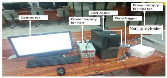
Figure 1.
Actual view of the experimental setup.

Table 1.
Experiments were conducted with the following input parameters.
3. Results and Discussion
Experimental Results Validation
The motivation to select these parameters was that voltage and discharge current could be changed by manipulating the flow of speed, “U”, the geometrical configuration, “G”, and the diameter, “D”, and by modifying L. As voltages were applied to this device, the ionic wind speed changed from -10 mm to 20 mm with a length value of 30 mm and a diameter of 25.4 mm, as presented in Figure 2a. Figure 2a presents the best results obtained for an available distance (G) between the electrodes, by increasing the applied voltage value and the velocity. By increasing the applied voltage (V), the electric field (E) increased; thus, velocity increased by increasing the voltage applied. Maximum wind velocity was achieved at an electrode distance between 5 mm and 10 mm. The maximum ionic wind velocity was achieved with a ratio of interelectrode distance to cylindrical diameter (G/D ratio) ranges between 0.3 and 0.5 mm.
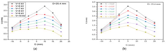
Figure 2.
The relationships between applied voltage (V), interelectrode space (G), and ionic wind velocity (U). (a) Experimental results (b) Literature results.
The output extracted results presented in Figure 2a were validated with the experimental results from Longnan Li [9] displayed in Figure 2b. The presented results show the best validation through comparisons with experimental studies in the literature.
Figure 3 depicts the relationship between current and voltage for an ionic wind generator. To avoid unstable current behavior, we only evaluated electrode lengths that are more than or equal to the distance between the electrodes. Additionally, there was no correlation between the discharge current or other parameters such as the electrode length or ionic wind velocity in the experiments using 10 mm and 50 mm cylindrical electrodes.
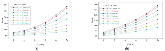
Figure 3.
The discharge current–voltage applied characteristics of the ionic wind generator. (a) Experimental results (b) Literature results.
Figure 3a presents that while increasing the voltage value, the current increased, and the current was maximized when the voltage value was 10 kV. These results were obtained at various distance (G) values between the electrodes and a diameter value of 25.4 mm. For negative distance values between the electrodes, the current dependency on the electric potential was unstable; in this case, it was limited to some extent due to the positive distance (G) value between the electrodes. Using a different cylindrical length electrode, there was no such dependency observed on the ionic wind velocity for other measurements.
To validate the experimental results, the findings were compared with those of Longnan Li, presented in Figure 3b. The obtained results best matched with the results in the literature, and in this way, the obtained results were validated.
4. Conclusions
The purpose of this study was to investigate the cooling effect of ionic wind which was developed by nail-to-cylinder electrodes on electronic devices. According to the experimental results, the ionic wind generator exhibited the following characteristics: optimum ionic wind voltage, discharge current, and ionic wind velocity. From this study, it is considered that a higher voltage applied enhances the strength of ionic wind. If a larger space between electrodes is used, the ionic wind velocity will be lower for the same applied voltage. In contrast, a larger space between electrodes (G) can extend the operating voltage range and generate higher ionic wind velocity. The maximum ionic wind velocity was achieved with a ratio of interelectrode distance to cylindrical diameter (G/D ratio) ranging between 0.3 and 0.5 mm. Ionic wind operation voltage increased from 5 kV to 10 kV when the interelectrode space was increased from -10 mm to 20 mm. It was possible to achieve the maximum ionic wind velocity when the interelectrode space was 10.0 mm, the diameter was 25.4 mm, and the applied voltage was 5 kV.
Author Contributions
Conceptualization, M.M.I.; methodology, M.M.I.; software, M.M.I.; validation, M.M.I.; formal analysis, M.M.I.; investigation, M.M.I.; data curation, M.M.I.; writing—original draft preparation, M.M.I.; writing—review and editing, M.M.I. and A.H.; supervision, A.H.; project administration, A.H. All authors have read and agreed to the published version of the manuscript.
Funding
This research received no external funding.
Institutional Review Board Statement
Not applicable.
Informed Consent Statement
Not applicable.
Data Availability Statement
Not applicable.
Conflicts of Interest
The authors declare no conflict of interest.
References
- Moreau, E. Airflow Control by Non-Thermal Plasma Actuators. J. Phys. D Appl. Phys. 2007, 40, 605–636. [Google Scholar] [CrossRef]
- Hsu, C.P.; Jewell-Larsen, N.E.; Sticht, C.; Krichtafovitch, I.A.; Mamishev, A.V. Heat Transfer Enhancement Measurement for Microfabricated Electrostatic Fluid Accelerators. In Proceedings of the 2008 Twenty-fourth Annual IEEE Semiconductor Thermal Measurement and Management Symposium, San Jose, CA, USA, 16–20 March 2008. [Google Scholar] [CrossRef]
- Jewell-Larsen, N.E.; Ran, H.; Zhang, Y.; Schwiebert, M.K.; Honer, K.A.; Mamishev, A.V. Electrohydrodynamic (Ehd) Cooled Laptop. In Proceedings of the 2009 25th Annual IEEE Semiconductor Thermal Measurement and Management Symposium, San Jose, CA, USA, 15–19 March 2009; pp. 261–266. [Google Scholar] [CrossRef]
- Jewell-Larsen, N.E. Optimization and Miniaturization of Electrostatic Air Pumps for Thermal Management. Ph.D. Thesis, University of Washington, Washington, DC, USA, 2013. [Google Scholar]
- Schlitz, D.; Singhal, V. An Electro-Aerodynamic Solid-State Fan and Cooling System. In Proceedings of the 2008 Twenty-Fourth Annual IEEE Semiconductor Thermal Measurement and Management Symposium, San Jose, CA, USA, 16–20 March 2008; pp. 46–49. [Google Scholar]
- Liang, W.J.; Lin, T.H. The Characteristics of Ionic Wind and Its Effect on Electrostatic Precipitators. Aerosol Sci. Technol. 1994, 20, 330–344. [Google Scholar] [CrossRef]
- Weinberg, F.; Carleton, F.; Kara, D.; Xavier, A.; Dunn-Rankin, D.; Rickard, M. Inducing Gas Flow and Swirl in Tubes Using Ionic Wind from Corona Discharges. Exp. Fluids 2006, 40, 231–237. [Google Scholar] [CrossRef]
- Kim, C.; Park, D.; Noh, K.C.; Hwang, J. Velocity and Energy Conversion Efficiency Characteristics of Ionic Wind Generator in a Multistage Configuration. J. Electrostat. 2010, 68, 36–41. [Google Scholar] [CrossRef]
- Li, L.; Lee, S.J.; Kim, W.; Kim, D. An Empirical Model for Ionic Wind Generation by a Needle-to-Cylinder Dc Corona Discharge. J. Electrostat. 2015, 73, 125–130. [Google Scholar] [CrossRef]
Publisher’s Note: MDPI stays neutral with regard to jurisdictional claims in published maps and institutional affiliations. |
© 2022 by the authors. Licensee MDPI, Basel, Switzerland. This article is an open access article distributed under the terms and conditions of the Creative Commons Attribution (CC BY) license (https://creativecommons.org/licenses/by/4.0/).