Abstract
This article describes the possibilities of using universal flat wagons to transport long cargoes and suggests measures for upgrading them, which involve the installation of superstructures on the load-bearing structures to keep the cargo from overturning. The study was conducted using the flat wagon model 13-401. Several options for implementing such superstructures have been considered. The load-bearing structure of the flat wagon was modeled as a rod system. The most rational option for upgrading was evaluated by assessing the force factors acting in the structure under the influence of external loads. According to the chosen upgrade option, a spatial model of the bearing structure of the flat wagon was built, and its strength was calculated using the finite element method. The proposed option was found to be appropriate. The results of the research can be used to improve the efficiency of transportation of long cargoes by universal flat wagons.
1. Introduction
Railway transport is a leading branch of the national economy and the backbone of economic development in many European countries [1,2]. Currently, railways transport a wide range of goods, among which are long cargoes, such as wood in whips, building materials, pipes, etc. [3,4,5,6]. Long cargoes are mainly transported by rail on specialized flat wagons equipped with vertical stanchions to keep the cargoes from overturning. However, the number of such wagons is limited and does not fully meet the demand for rail transportation of long cargoes. Other types of wagons are required, such as universal flat wagons or open wagons.
Universal flat wagons are equipped with wooden stanchions mounted on their longitudinal beams to hold long cargoes. These stanchions are fastened with brackets welded to the vertical parts of the I-beams that form the longitudinal beams of the frame. However, under operating loads, these wooden stanchions can be damaged, which can result in the cargo falling apart, jeopardizing traffic safety. Thus, there is a need to upgrade the flat wagons used for transporting long cargoes.
Many scientific studies are devoted to designing, improving, and increasing the efficiency of flat wagons. Study [7] deals with the use of a removable module to adapt flat wagons to the transportation of long cargoes. The structural feature of this module includes the use of elastic–frictional bonds that reduce the dynamic loads in operation. An appropriate scientific substantiation of the removable module design is given. However, the use of the removable module requires an appropriate maintenance and repair system, which complicates its large-scale implementation.
In [8], the authors analyze the influence of dynamic loads on the strength of the load-bearing structure of a flat wagon used for transporting long cargoes. The peculiarities of the modal analysis of the flat wagon design are described, and it is also proposed to adjust the theoretical models used in determining the load of the flat wagon bearing structure. However, no solution was provided for how to improve the efficiency of the transportation of long cargoes on flat wagons.
In study [9], the authors propose a long-base flat wagon design with a variable length of cargo space. Their static and dynamic structural analysis makes it possible to substantiate the design solutions proposed for the flat wagon. However, the authors did not investigate the possibility of using this flat wagon for transporting long cargoes.
A similar disadvantage can be seen in [10]. The authors thoroughly investigate the issue of determining the load of the flat wagon under operating conditions, but do not consider the possibility of its adaptation to transporting long cargoes.
Study [11] is devoted to evaluating the strength of the long-base structure of a flat wagon. The most loaded areas of the flat wagon construction are calculated by determining the bending moments in its sections. The obtained results are confirmed by a computer simulation of the strength of the flat wagon bearing structure using the finite element method. However, the authors did not determine the load of the flat wagon when transporting long cargoes.
Article [12] highlights the features of determining the load of a long-base flat wagon and describes some new materials that can be used to improve its structural strength. The materials were tested using the example of a flat wagon loaded with containers. However, the issue of using flat wagons for transporting long cargoes was not investigated.
The loading of the bearing structure of a flat wagon (series Smnps 194) is also studied in [13]. This wagon is equipped with side stanchions, which make it possible to improve the stability of cargoes against overturning during rail transportation. The authors highlight the features of determining the strength of the flat wagon bearing structure. Special attention is paid to the study of stresses in the areas of interaction of the stanchions with the longitudinal beams of the frame. However, the stanchion’s height makes it impossible to fully utilize the payload capacity of the flat wagon when transporting long cargoes, in particular, wood in whips.
The authors also propose a method for evaluating the safety of a freight wagon against the derailment criterion using the example of a flat wagon [14]. However, the impact of the cargoes, including long cargoes, on the stability of the wagon against overturning was not investigated.
This review of scientific publications has proved that the issues of determining the loading and improving the safety of flat wagons are relevant. Moreover, the issue of improving the efficiency of rail transportation of long cargoes through the adaptation (upgrading) of flat wagons, which is raised in many articles, requires further attention.
In this regard, the purpose of this article is to highlight the results of a study on the feasibility of upgrading a universal flat wagon for transporting long cargoes. The objective of the research has been achieved by completing the following tasks:
- -
- Determine the force factors in the upgraded load-bearing structure of the flat wagon.
- -
- Calculate the strength of the upgraded load-bearing structure of the flat wagon.
2. Materials and Methods
This study proposed to upgrade universal flat wagons so that they can be used for the transportation of long cargoes by installing superstructures to prevent the cargo being transported from overturning (Figure 1).
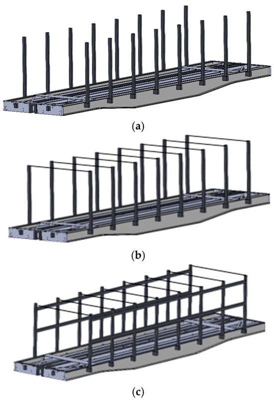
Figure 1.
The upgrade options for the load-bearing structure of a flat wagon: (a) metal stanchions; (b) stanchions connected by lashings; (c) frame walls connected by lashings.
All three upgrade options include superstructures made of Steel 09G2S for cargo retention. The material of the superstructures is identical to that of the flat wagon bearing structure.
The most rational variant of the superstructure and the stanchion thickness were determined through the calculation of the load-bearing structure of the flat wagon. The purpose of this calculation was to determine the internal force factors acting in the superstructures under external loads. The load-bearing structure of the flat wagon was modeled as a rod system (Figure 2) in LIRA-CAD [15,16,17,18]. It was also taken into account that the structure was loaded with gross weight, and the stanchions were subjected to transverse load. The intensity of this load included the transverse inertial force ΔFn from the stack and was distributed along the stanchion height [7]:
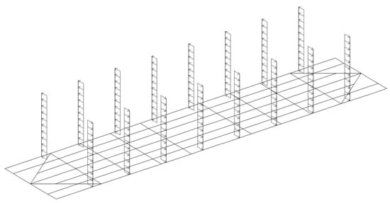
Figure 2.
The design diagram of the flat wagon bearing structure.
Herewith,
where n is the coefficient used to design the flat wagon; Fn is the transverse inertial load, which includes the force from the stack and the centrifugal force; W′ is the wind load; and Ffrn is the friction force.
It was taken into account that on one side of the wagon, this load was positive (+), and on the other side, it was negative (−). The wagon was secured on the center plates.
Taking into account the results of the calculations, diagrams of the force factors acting in the load-bearing structure of the flat wagon were obtained (Figure 3 and Figure 4). Consequently, the maximum transverse force acts at the stanchion base and amounts to 194 kN (Figure 3). The bending moments had a similar distribution pattern (Figure 4). The maximum bending moment is also at the stanchion base and amounts to 224 kN m. These force factors have an alternating character: stretching is shown in orange and compression is shown in blue (Figure 3 and Figure 4).
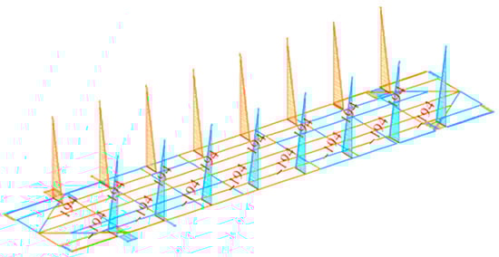
Figure 3.
The diagram of transverse forces acting on the bearing structure of the flat wagon (kN).
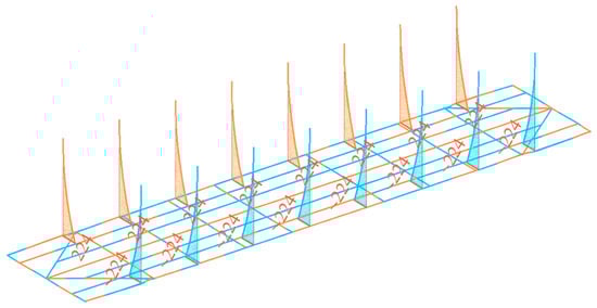
Figure 4.
The diagram of bending moments acting on the load-bearing structure of the flat wagon (kN·m).
The force factors in the load-bearing structure of the flat wagon with stanchions connected by lashings (chains or ropes) were investigated by means of a computational diagram, as shown in Figure 5. The diagram of fixation and applying loads is identical to the one shown in Figure 2.
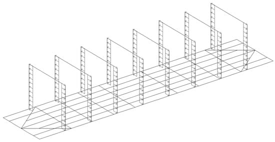
Figure 5.
The calculation diagram of the load-bearing structure of the flat wagon with stanchions connected by lashings.
Taking into account the results of the calculations, it was found that the maximum transverse force acting on the stanchion is 101 kN (Figure 6), which is more than half that of the force acting on the structure without tightening. This force is distributed alternately along the stanchion height: it is negative on the side where the stanchion is loaded in its lower part, and it is positive in its upper part. On the opposite side of the bearing structure of the flat wagon, it has the opposite distribution; that is, on the bottom of the stanchion, it has a positive value, and on the top, it has a negative value.
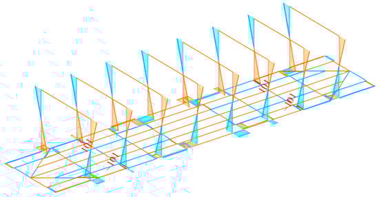
Figure 6.
The diagram of the transverse forces acting on the bearing structure of the flat wagon with stanchions connected by lashings (kN).
The diagram of bending moments is a parabola with its maximum in the middle (Figure 7). On the side where the stanchions are loaded, the bending moment is 55.3 kN·m; on the opposite side, the numerical value of the bending moment is negative.
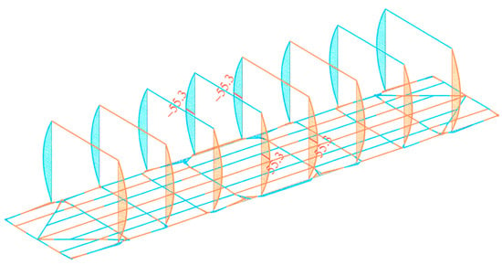
Figure 7.
The diagram of bending moments acting on the bearing structure of the flat wagon with stanchions connected by lashings (kN·m).
Therefore, the use of lashing rods can reduce the load of the flat wagon structure. The option of using side frame walls connected by lashing rods for the flat wagon was also considered (Figure 8).
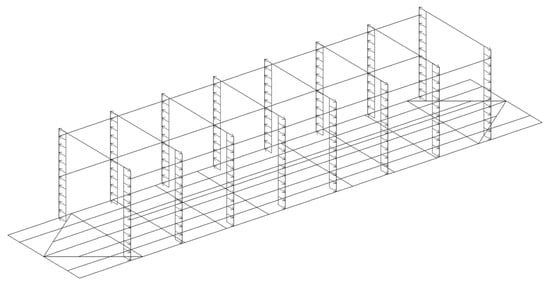
Figure 8.
The design diagram of the load-bearing structure of the flat wagon with frame walls connected by lashings.
Taking into account the results of the calculations, it was found that the diagram of the transverse forces (Figure 9) has a form similar to that obtained for the bearing structure of the flat wagon with vertical stanchions connected by lashing rods. The value of the transverse forces is 102 kN, which is almost equal to that obtained for the diagram in Figure 6.
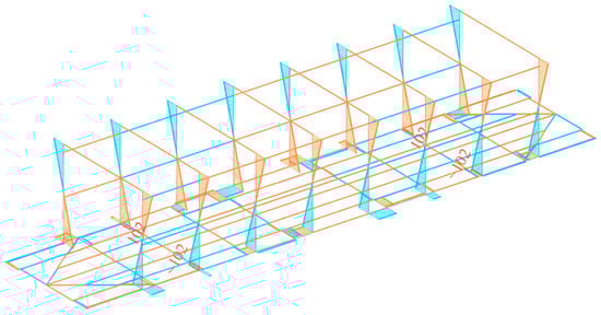
Figure 9.
The diagram of the transverse forces acting on the bearing structure of the flat wagon with frame walls connected by lashing rods (kN).
The diagram of the bending moments is shown in Figure 10. They have the form of a parabola with a maximum of 54.6 kN·m at the center. The obtained value of the bending moment is 1.2% less than that obtained for the design shown in Figure 7.
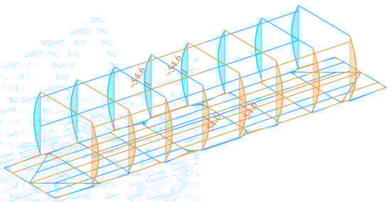
Figure 10.
The diagram of bending moments acting on the bearing structure of the flat wagon with frame walls connected by lashings (kN·m).
3. Results and Discussion
The vertical stanchion thickness was determined on the basis of the stanchion pocket profile (Figure 11). Therefore, the lower part of the stanchion should have a width b = 80 mm and a length l = 110 mm.
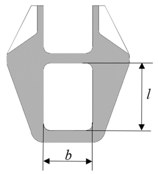
Figure 11.
The stanchion pocket (top view).
The optimal thickness of the working part of the stanchion (the contact area with the load (Figure 12)) was chosen using the moment of resistance of its cross-section using the option in the SolidWorks software (version 2025) package.
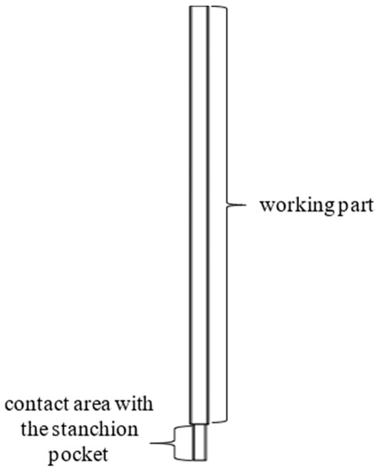
Figure 12.
The side view of the stanchion.
The moment of resistance at which the strength of the stanchion was observed was defined as the ratio of the bending moment M acting in its section to the permissible stresses [σ] of its material, i.e.,
Permissible stresses [σ] for Steel 09G2S were considered equal to 310.5 MPa in accordance with [19]. Then, W = 178 cm3. The corresponding geometry of the stanchion was created in SolidWorks by varying the wall thickness δ (Figure 13).
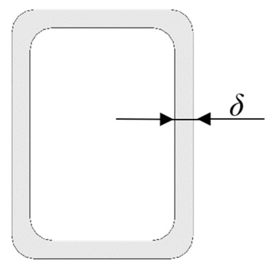
Figure 13.
The cross-section of the stanchion.
Based on the calculations, it was found that with a width of the working part of the stanchion of 110 mm and a height of 140 mm, the thickness of its wall should be 10 mm. In this case, W = 178 cm3. The weight of one stanchion is 99 kg. At the same time, the tare weight of the flat wagon increases by 1.5 tons. The stanchion is shown in Figure 12.
The selected parameters of the stanchion were checked by means of the strength calculation of the load-bearing structure of the upgraded flat wagon using the finite element method [20,21,22,23] implemented in SolidWorks simulation. The design diagram of the load-bearing structure of the flat wagon is shown in Figure 14.
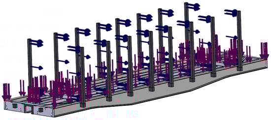
Figure 14.
The design diagram of the load-bearing structure of the flat wagon.
The loads taken into account were identical to those used in the design diagrams of the rod systems. The model was fixed to the horizontal surfaces of the center plates [24,25,26]. Here, a rigid connection was applied [27,28,29,30]. That is, the friction forces in the center plate/center bowl units were neglected. The upper parts of the stanchion had a bond simulating their interaction with the lashings.
The finite element model was formed by tetrahedra [31,32,33,34,35]. The model had 357,265 elements and 121,598 nodes. The maximum size of the element was 200 mm, and the minimum size was 40 mm. The number of tetrahedra was calculated graphically and analytically. The material of construction was low-alloy Steel 09G2S [36,37,38,39,40]. The results are shown in Figure 15 and Figure 16. The most loaded components of the flat wagon structure are the connecting structures between the longitudinal beams. The highest stresses in these elements were recorded as 187.4 MPa (Figure 15), which is less than permissible.
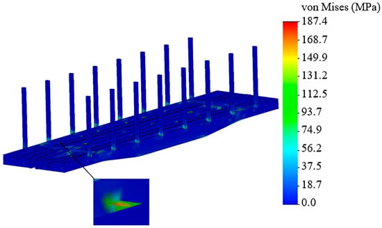
Figure 15.
The stress state of the load-bearing structure of the flat wagon.
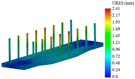
Figure 16.
The displacements in the units of the flat wagon bearing structure.
The maximum displacements occurred in the upper parts of the vertical stanchions placed behind the center of the longitudinal beam. These displacements were 2.4 mm (Figure 16).
The results of the calculations have demonstrated the feasibility of the proposed solutions for improving the flat wagon design.
This study has advantages over other studies. Unlike the studies presented in [7,8,11,12], the proposed improvement of the load-bearing structure of the flat wagon does not require significant capital investment. In contrast to the studies described in [9,10], the solution presented can be used for a flat wagon that transports long cargoes. The same advantage can be seen when comparing it to the studies presented in [13,14].
The disadvantage of this study is that the authors only investigated a transverse load in the improved flat wagon design. However, this is going to be resolved through investigation in a further study, with the results presented in further publications. Also, the authors plan to optimize the vertical stanchions according to the criterion of minimum material consumption. They can also reduce the load by using an energy-absorbing filler in the structure.
International regulatory documents [41,42,43] will also be considered during further optimization of the vertical struts. This will allow the designed wagon to be operated not only on a 1520 mm gauge, but also on a 1435 mm gauge.
The limitation of the study is that the calculations did not consider the heaped loading mode of the flat wagon bearing structure.
The solutions proposed within the framework of the study can be used to upgrade universal flat wagons so that they can be used for transporting long cargoes, which will increase the efficiency of railway transportation.
4. Conclusions
1. The force factors in the upgraded bearing structure of a flat wagon have been determined. Three upgrade options have been considered: metal stanchions, stanchions connected by lashing rods, and walls connected by lashing rods. It has been found that the use of stanchions connected by lashing rods is the most rational design option. Here, the bending moment on the side of the loaded stanchions is 55.3 kN·m, and on the opposite side, the numerical value of the bending moment is negative. By taking into account the determined bending moment according to the moment of resistance of the cross-section, the parameters of the vertical stanchion profile have been selected: the width of the working part of the stanchion is 110 mm, the height is 140 mm, and the wall thickness is 10 mm. Here, W=178 cm3. The weight of one stanchion is 99 kg. The tare weight of the upgraded flat wagon increases by 1.5 tons. However, further upgrades, which have already been planned, can reduce the stanchion weight.
2. The strength of the upgraded load-bearing structure of the flat wagon has been calculated. It has been found that the maximum stresses in the load-bearing structure of the flat wagon are 187.4 MPa, and they do not exceed the permissible limit. These stresses occur in the structures that connect the longitudinal beams. The maximum displacements occur in the upper parts of the vertical stanchions located at the center of the longitudinal beam and are measured as 2.4 mm.
Author Contributions
Conceptualization, A.L. and J.G.; methodology, A.L.; software, M.P.; validation, A.L., J.G. and M.P.; formal analysis, J.G.; investigation, A.L. and J.G.; resources, M.P.; data curation, A.L.; writing—original draft preparation, A.L. and J.G.; writing—review and editing, A.L. and J.G.; visualization, A.L. and J.G.; supervision, M.P.; project administration, A.L. and J.G.; funding acquisition, A.L. and J.G. All authors have read and agreed to the published version of the manuscript.
Funding
This publication was supported by the Cultural and Educational Grant Agency of the Ministry of Education of the Slovak Republic under the project KEGA 024ZU-4/2024: Deepening the knowledge of university students in the field of construction of means of transport by carrying out professional and scientific research activities in the field. It was also supported by the Slovak Research and Development Agency of the Ministry of Education, Science, Research, and Sport under the project VEGA 1/0513/22: Investigation of the properties of railway brake components in simulated operating conditions on a flywheel brake stand. Funding was also received from the EU NextGenerationEU project under the Recovery and Resilience Plan for Slovakia, project No. 09I03-03-V01-00131.
Institutional Review Board Statement
Not applicable.
Informed Consent Statement
Not applicable.
Data Availability Statement
The data are contained within the article.
Conflicts of Interest
The authors declare no conflicts of interest.
References
- Gerlici, J.; Lovska, A.; Kozáková, K. Research into the Longitudinal Loading of an Improved Load-Bearing Structure of a Flat Car for Container Transportation. Designs 2025, 9, 12. [Google Scholar] [CrossRef]
- Dižo, J.; Blatnický, M.; Harušinec, J.; Falendysh, A. Modification and analyses of structural properties of a goods wagon bogie frame. Diagnostyka 2019, 20, 41–48. [Google Scholar] [CrossRef]
- Kasimu, A.; Zhou, W.; Yan, H.; Wang, Y.; Shen, C.; Zhang, Q. Evaluation of the vehicle-cargo and vehicle-trackside clearance of long and big railway freight vehicles. Alex. Eng. J. 2025, 119, 22–34. [Google Scholar] [CrossRef]
- Butko, T.; Prokhorov, V.; Kalashnikova, T.; Riabushka, Y. Organization of railway freight short-haul transportation on the basis of logistic approaches. Procedia Comput. Sci. 2019, 149, 102–109. [Google Scholar] [CrossRef]
- Petrukhin, V.M. Modular vantage units—Modular vantage transport complexes for intermodal transportation of bulk cargo. News Mech. Eng. Transp. 2023, 2, 141–147. (In Ukrainian) [Google Scholar] [CrossRef]
- Pokrovskaya, O.D.; Migrov, A.A.; Mukhutdinova, Z.A. Features of intermodal transportation of grain cargo. Transp. Tech. Educ. Pract. 2025, 6, 61–68. [Google Scholar] [CrossRef]
- Vatulia, G.; Lovska, A.; Pavliuchenkov, M.; Nerubatskyi, V.; Okorokov, A.; Hordiienko, D.; Vernigora, R.; Zhuravel, I. Determining patterns of vertical load on the prototype of a removable module for long-size cargoes. East.-Eur. J. Enterp. Technol. 2022, 6/7, 21–29. [Google Scholar] [CrossRef]
- Silva, R.; Ribeiro, D.; Bragança, C.; Costa, C.; Arêde, A.; Calçada, R. Model Updating of a Freight Wagon Based on Dynamic Tests under Different Loading Scenarios. Appl. Sci. 2021, 11, 10691. [Google Scholar] [CrossRef]
- Šťastniak, P.; Kurčík, P.; Pavlík, A. Design of a new railway wagon for intermodal transport with the adaptable loading platform. MATEC Web Conf. 2018, 235, 00030. [Google Scholar] [CrossRef][Green Version]
- Das, A.; Agarwal, G. Compression, tension & lifting stability on a meter gauge flat wagon: An experimental approach. Aust. J. Mech. Eng. 2020, 2, 1113–1125. [Google Scholar] [CrossRef]
- Ishchenko, V.M.; Fedosov-Nikonov, D.V. Long Wheelbase Flat Wagons: Structural Strength. Metall. Min. Ind. 2017, 8, 26–31. [Google Scholar]
- Fedosov-Nikonov, D.V.; Sulym, A.O.; Ilchyshyn, V.V.; Safronov, O.M.; Kelrikh, M.B. Study of strength characteristics of the long wheelbase flatcars. IOP Conf. Ser. Mater. Sci. Eng. 2020, 985, 0120229. [Google Scholar] [CrossRef]
- Stoilov, V.; Slavchev, S.; Maznichki, V.; Purgic, S. Analysis of some problems in the theoretical wagon strength studies due to the imperfection of the European legislation. IOP Conf. Ser. Mater. Sci. Eng. 2019, 618, 012045. [Google Scholar] [CrossRef]
- Stoilov, V.; Slavchev, S.; Purgic, V.M.S. Method for Theoretical Assessment of Safety against Derailment of New Freight Wagons. Appl. Sci. 2023, 13, 12698. [Google Scholar] [CrossRef]
- Barabash, M.S.; Soroka, M.M.; Sur’yaninov, M.G. Nelinijna Budivelna Mehanika z PK Lira-Sapr; Ekologiya: Odesa, Ukraine, 2018; p. 248. (In Ukrainian) [Google Scholar]
- Kravchuk, V.; Vegera, P.; Khmil, R. Modeling the impact of damage to the concrete cover and the compressed rebar of a reinforced concrete beam in “LIRA-SAPR”. Theory Build. Pract. 2025, 1, 19–30. [Google Scholar] [CrossRef]
- Genzerskyi, Y.; Barabash, M.; Trusov, I.; Pervushova, L. Methodology for assessing the seismic resistance of building structures and structures of nuclear power plants in the LIRA CAD system. Resist. Mater. Theory Struct. 2023, 111, 125–139. (In Ukrainian) [Google Scholar]
- Barabash, M.; Pisarevskyi, B.; Bashinsky, Y. Material damping in dynamic analysis of structures (with LIRA-SAPRprogramm). Civ. Environ. Eng. 2020, 16, 63–70. [Google Scholar] [CrossRef]
- DSTU 7598:2014; Freight Wagons. General Requirements for Calculations and Design of New and Modernized 1520 mm Gauge Wagons (Non-Self-Propelled). Ministry of Economic Development of Ukraine: Kyiv, Ukraine, 2015; p. 250. (In Ukrainian)
- Dižo, J.; Blatnický, M.; Harušinec, J.; Suchánek, A. Assessment of dynamics of a rail vehicle in terms of running properties while moving on a real track model. Symmetry 2020, 14, 536. [Google Scholar] [CrossRef]
- Melnik, R.; Koziak, S.; Dižo, J.; Kuźmierowski, T.; Piotrowska, E. Feasibility study of a rail vehicle damper fault detection by artificial neural networks. Eksploatacja i Niezawodnosc—Maint. Reliab. 2023, 25, 1–11. [Google Scholar] [CrossRef]
- Dižo, J.; Blatnický, M.; Steišunas, S. Assessment of negative effects of a coach running with the wheel-flat on a track by means of simulation computations. Diagnostyka 2017, 18, 31–37. [Google Scholar]
- Vatulia, G.L.; Lovska, A.O.; Krasnokutskyi, Y.S. Research into the transverse loading of the container with sandwich-panel walls when transported by rail. IOP Conf. Ser. Earth Environ. Sci. 2023, 1254, 012140. [Google Scholar] [CrossRef]
- Gerlici, J.; Lovska, A.; Vatulia, G.; Pavliuchenkov, M.; Kravchenko, O.; Solcansky, S. Situational adaptation of the open wagon body to container transportation. Appl. Sci. 2023, 13, 8605. [Google Scholar] [CrossRef]
- Gerlici, J.; Lovska, A.; Pavliuchenkov, M.; Harušinec, J. Investigation of the strength and dynamic load on a wagon covered with tarpaulin for 1520 mm gauge lines. Appl. Sci. 2024, 14, 6810. [Google Scholar] [CrossRef]
- Lovska, A.; Stanovska, I.; Kyryllova, V.; Okorokov, A.; Vernigora, R. Determining the vertical load on a container with a floor made of sandwich panels transported by a flat wagon. East.-Eur. J. Enterp. Technol. 2024, 6/7, 6–14. [Google Scholar] [CrossRef]
- Panchenko, S.; Gerlici, J.; Vatulia, G.; Lovska, A.; Ravlyuk, V.; Harusinec, J. Studying the load of composite brake pads under high-temperature impact from the rolling surface of wheels. EUREKA Phys. Eng. 2023, 4, 155–167. [Google Scholar] [CrossRef]
- Wróbel, A.; Płaczek, M.; Buchacz, A. An Endurance Test of Composite Panels. Solid State Phenom. 2017, 260, 241–248. [Google Scholar] [CrossRef]
- Fischer, S.; Harangozó, D.; Németh, D.; Kocsis, B.; Sysyn, M.; Kurhan, D.; Brautigam, A. Investigation of heat-affected zones of thermite rail welding. Facta Univ. Ser. Mech. Eng. 2024, 22, 689–710. [Google Scholar] [CrossRef]
- Fischer, S. Investigation of the settlement behavior of ballasted railway tracks due to dynamic loading. Spectr. Mech. Eng. Oper. Res. 2025, 2, 24–46. [Google Scholar] [CrossRef]
- Patrascu, A.I.; Hadar, A.; Pastrama, S.D. Structural Analysis of a Freight Wagon with Composite Walls. Mater. Plast. 2020, 57, 140–151. [Google Scholar] [CrossRef]
- Płaczek, M.; Wróbel, A.; Olesiejuk, M. Modelling and arrangement of composite panels in modernized freight cars. MATEC Web Conf. 2017, 112, 06022. [Google Scholar] [CrossRef]
- Lee, H.-A.; Jung, S.-B.; Jang, H.-H.; Shin, D.-H.; Lee, J.U.; Kim, K.W.; Park, G.-J. Structural-optimization-based design process for the body of a railway vehicle made from extruded aluminum panels. Proc. Inst. Mech. Eng. F J. Rail. Rapid Transit 2015, 230, 1283–1296. [Google Scholar] [CrossRef]
- Ou, C.; Li, B. Research and application of new multimodal transport equipment-swap bodies in China. E3S Web Conf. 2020, 145, 02001. [Google Scholar] [CrossRef]
- Gerlici, J.; Lovska, A.; Pavliuchenkov, M. Study of the dynamics and strength of the detachable module for long cargoes under asymmetric loading diagrams. Appl. Sci. 2024, 14, 3211. [Google Scholar] [CrossRef]
- Al-Sukhon, A.; ElSayed, M.S.A. Design optimization of hopper cars employing functionally graded honeycomb sandwich panels. Proc. Inst. Mech. Eng. Part F J. Rail Rapid Transit 2021, 236, 8. [Google Scholar] [CrossRef]
- Jeong, D.; Tyrell, D.; Carolan, M.; Perlman, A.B. Improved Tank Car Design Development: Ongoing Studies on Sandwich Structures. In Proceedings of the 2009 ASME Joint Rail Conference, Pueblo, CO, USA, 3–5 March 2009; pp. 1–10. [Google Scholar]
- Sastniak, P.; Moravčík, M. Freight bogie prototype properties analysis by means of simulation computations. Manuf. Technol. 2017, 17, 27–28. [Google Scholar] [CrossRef]
- Gzaiel, M.; Triki, E.; Barkaoui, A. Experimental study and numerical simulation of cutting and tearing of silicone rubber using extended finite element method. J. Appl. Comput. Mech. 2024, 10, 465–478. [Google Scholar]
- Baier, A.; Majzner, M. Application of feature based method in constructing innovative sheathing of railway wagons. J. Achiev. Mater. Manuf. Eng. 2012, 52, 1–98. [Google Scholar]
- UIC Leaflet 577-2012; Wagon Stresses. International Union of Railways (UIC): Paris, France, 2012; 26p.
- EN 12663-2:2010; Railway Applications—Structural Requirements of Railway Vehicle Bodies—Part 2: Freight Wagons. European Committee for Standardization: Brussels, Belgium, 2010; 50p.
- ERRI B12/Rp17; Wagons. Programme of Tests to Be Carried Out on Wagons with Steel Underframe and Body Structure (Suitable for Being Fitted with the Automatic Buffing and Draw Coupler) and on Their Cast Steel Frame Bogies. European Rail Research Institute: Utrecht, The Netherlands, 1997; 41p.
Disclaimer/Publisher’s Note: The statements, opinions and data contained in all publications are solely those of the individual author(s) and contributor(s) and not of MDPI and/or the editor(s). MDPI and/or the editor(s) disclaim responsibility for any injury to people or property resulting from any ideas, methods, instructions or products referred to in the content. |
© 2026 by the authors. Licensee MDPI, Basel, Switzerland. This article is an open access article distributed under the terms and conditions of the Creative Commons Attribution (CC BY) license.