Abstract
Active Debris Removal (ADR) missions demand precise and rapid controllers that lower collision risks specifically in the capture phase of tumbling objects. Sliding Mode Control (SMC), in general, offers robustness against model uncertainties. However, traditional reaching laws often face slow convergence when the chaser is too far from the target state. In this paper, we address this particular limitation and present the first application of Power Rate Reaching Law Sliding Mode Control (PRRL-SMC) to the 6-DOF coupled dynamics of a CubeSat-based debris capture mission in both the pre-capture tracking and post-capture stabilization phases in the case of tumbling debris. To show the strength of our work, we evaluate the proposed controller against Proportional–Derivative (PD), Linear Quadratic Regulator (LQR), second-order SMC (SOSMC), and terminal SMC (TSMC) for the pre-capture tracking and post-capture stabilization phases. By numerical simulations we show that PRRL-SMC reduces convergence time extremely and achieves stable capture in 7.6 s. This time it is 24.6 s for LQR and 28.1 s for SOSMC. The controller also handles the abrupt inertia variations of the combined stack post-capture successfully. This is efficient for proximity operations because of their importance in timing and fuel conservation.
1. Introduction
The Earth is surrounded. The continuous production of space debris is a threat to the future of space activities, especially if something collides with it and generates more debris (also known as the Kessler Syndrome [1]). To avoid this catastrophe, Active Debris Removal (ADR) missions are proposed to capture and deorbit or relocate defunct satellites, rocket bodies, and other space debris. Multiple comprehensive reviews are written on ADR missions [2,3,4,5,6]. CubeSats are cost-effective platforms for ADR missions [7]. Their rendezvous phase needs precise control, especially if the debris is non-cooperative or tumbling [8]. Plus, their control system must be robust to uncertainties, external disturbances, and the dynamic nature of the debris. For the rendezvous and capture phases, various control strategies are proposed. This includes classical methods such as PD control in the work of Dubanchet et al. [9] (2015); optimal control approaches such as LQR in the works of Yang [10] (2012), Chen et al. [11] (2024), and Carer et al. [12] (2025); and nonlinear techniques such as Sliding Mode Control (SMC) in the works of Liu et al. [13] (2024) and Sampath et al. [14] (2024). While the LQR approach controls linearized systems well, its performance degrades in the presence of strong nonlinearities and disturbances that are unavoidable in debris capture missions. Standard SMC offers robustness but can suffer from chattering [15], and chattering is troublesome for satellite actuators. Higher-order and non-singular SMC approaches like second-order Sliding Mode Control (SOSMC) and Terminal Sliding Mode Control (TSMC) tackle some of these issues [16]. The higher-order integral form of SMC offers better performance and finite-time convergence properties in most cases, especially where chaotic or uncertain factors are present (refer to [17] for a full explanation).
The specific challenge that remains is that standard reaching laws in SMC can be slow to converge when the system states are far from the sliding surface. This is a norm during the initial approach to a tumbling object. In this paper, we concentrate on the Power Rate Reaching Law Sliding Mode Control (PRRL-SMC) as a solution to this problem. The Power Rate Reaching law forces the system to converge to the sliding surface significantly faster when the error is large. This paper focuses on applying PRRL-SMC to CubeSat-based debris capture. The Power Rate Reaching converges to the sliding surface faster when the system states are far from the surface. To our knowledge, PRRL-SMC has not been used in ADR applications to date; however, many papers are working on the theory and characteristics of PRRL-SMC as a general, such as [18,19,20,21,22].
In this paper, the design of the five control strategies is explained, which are as follows: the Proportional–Derivative (PD) control, Linear Quadratic Regulator (LQR), second-order Sliding Mode Control (SOSMC), Terminal Sliding Mode Control (TSMC), and Power Rate Reaching Law Sliding Mode Control (PRRL-SMC). Each controller is designed for both the pre-capture phase (controlling the Chaser’s relative position and attitude) and the post-capture phase (stabilizing the combined Chaser–Debris stack). Here, we present a comparative simulation study that carefully and fairly evaluates PRRL-SMC against PD, LQR, SOSMC, and TSMC controllers.
2. System Modeling
The dynamics of the Chaser CubeSat relative to the tumbling debris object in a Low Earth Orbit (LEO) are modeled using the Hill–Clohessy–Wiltshire (HCW) equations [23] for relative translation and Euler’s equations for rotational dynamics. Considering the assumptions and parameters used in our work, both the Chaser CubeSat and debris are treated as rigid bodies. The debris rotational dynamics are simulated as uncontrolled; the debris starts with an initial angular velocity and is tumbling, and the capture transition to combined dynamics is approximated based on the pre-capture state, without rigorous momentum conservation. Sensor noise is modeled as additive white Gaussian noise on relative position, attitude, and angular velocity. Actuators are considered ideal force/torque generators with simple saturation limits, and we have not considered their dynamics, minimum impulse bits, or dead zones. The Earth’s gravitational parameter is assumed to be , and the target orbit radius (altitude + Earth radius) to be . The mean motion of the reference orbit is calculated from and . The other parameters include the mass of the chaser (9 kg, or 6U), the moment of inertia matrix for the Chaser CubeSat (, the mass of the debris (5 kg, or a defunct 3U CubeSat), the moment of inertia matrix for the Debris Object (, the total simulation time (), distance threshold for capture (), angle threshold for capture (20°), relative angular velocity threshold for capture (), maximum torque for attitude control (), maximum force for position control (), maximum impulse for thrusters (), minimum impulse bit for thrusters (), reaction wheel rate limit (), and the power rate parameter (0 < < 1).
2.1. Relative Translational Dynamics
Assuming the debris is in a circular reference orbit, the relative position and relative velocity of the Chaser with respect to the debris in the local–vertical, local–horizontal (LVLH) frame are governed by the HCW equations, as follows [24].
where is the mean motion of the reference orbit, is the mass of the Chaser, and is the translational control force applied by the Chaser in the LVLH frame. After capture, the dynamics are those of the combined Chaser–Debris stack. The translational dynamics of the combined center of mass (CoM) in the LVLH frame are as follows.
where is the combined mass and is the translational control force applied to the combined stack.
2.2. Rotational Dynamics
The rotational dynamics of a rigid body are described by Euler’s equations as follows [25].
where is the moment of inertia tensor, is the angular velocity in the body frame, and is the applied control torque.
For the Chaser, before capture, we can say,
For the debris (assumed uncontrolled), we can say,
After capture, the rotational dynamics are those of the combined body as follows.
Attitude is represented using quaternions (where is scalar, is the vector part and ) with kinematics given by the following.
where is the angular velocity quaternion. Please note that the ⊗ symbol refers to the quaternion multiplication (Hamilton product). It is a specific algebraic operation distinct from standard matrix multiplication. For two quaternions and , their product is explicitly defined as .
3. Controller Design
Now we explain the controller design. In this section, the design of the five control strategies is explained, which are as follows: the Proportional–Derivative (PD) control, Linear Quadratic Regulator (LQR), second-order Sliding Mode Control (SOSMC), Terminal Sliding Mode Control (TSMC), and Power Rate Reaching Law Sliding Mode Control (PRRL-SMC). Each controller is designed for both the pre-capture phase (controlling the Chaser’s relative position and attitude) and the post-capture phase (stabilizing the combined Chaser–Debris stack). For all controllers, the control objective in the pre-capture phase is to bring the Chaser to a desired relative position and align its attitude with that of the debris . In the post-capture phase, the objective is to stabilize the combined stack’s angular velocity to zero and align its attitude with the LVLH frame.
3.1. Proportional–Derivative (PD) Control
PD control is a broadly used linear control method. In this controller, the control command (control input) is proportional to the error and its derivative.
3.1.1. PD Translational Control (Pre- and Post-Capture)
The translational control force is given by the following.
where is the position error, is the velocity error, and and are positive definite gain matrices. In this simulation, is the desired Rendezvous Proximity Operations (RPO) position and .
3.1.2. PD Rotational Control (Pre-Capture—Chaser)
The Chaser’s attitude control torque is based on the attitude error vector and angular velocity as follows.
where and are positive definite gain matrices. The attitude error vector is derived from the error quaternion between the current Chaser attitude and the desired Chaser attitude (which is the debris attitude in the pre-capture phase).
3.1.3. PD Rotational Control (Post-Capture—Combined)
The combined stack’s attitude control torque is as follows.
where is the attitude error vector between the combined body’s attitude and the desired LVLH alignment, and and are positive definite gain matrices.
3.2. Linear Quadratic Regulator (LQR)
LQR is an optimal control technique for linear systems that minimizes a quadratic cost function of the state and control inputs. The controller gain is constant for a given system and cost function.
3.2.1. LQR Translational Control (Pre- and Post-Capture)
LQR is applied to the linearized HCW dynamics. The state vector for translational control is . The control input is the force per unit mass. The LQR gain matrix is computed by minimizing a cost function involving weighted state and control input. The control force is then as follows.
where is pre-capture and post-capture.
3.2.2. LQR Rotational Control (Pre-Capture—Chaser)
LQR is applied to the linearized rotational dynamics. The state vector for rotational control is approximately . The LQR gain matrix is computed, and the control torque is as follows.
3.2.3. LQR Rotational Control (Post-Capture—Combined)
Similarly, for the combined stack, the state vector is , where . The LQR gain matrix is computed, and the control torque is as follows.
3.3. Second-Order Sliding Mode Control (SOSMC)
SOSMC is a type of higher-order sliding mode control that aims to reduce chattering while maintaining robustness. It drives a second-order sliding variable to zero in finite time.
3.3.1. SOSMC Translational Control (Pre- and Post-Capture)
A common SOSMC approach uses the sliding surface , similar to first-order SMC. A simplified SOSMC control law can take the following form:
where is the relevant mass, and are positive gains, and is the boundary layer thickness for the saturation function. The full derivation involves the time derivative of the sliding surface and handling system dynamics.
3.3.2. SOSMC Rotational Control (Pre-Capture—Chaser)
The rotational sliding surface . A simplified SOSMC torque command in the body frame is as follows.
where and are positive gains, and is the boundary layer thickness.
3.3.3. SOSMC Rotational Control (Post-Capture—Combined)
For the combined stack, the sliding surface is . The SOSMC torque is as follows:
with appropriate gains and boundary layer thickness.
3.4. Terminal Sliding Mode Control (TSMC)
TSMC is designed to achieve convergence to the sliding surface in finite time, which can lead to faster transient response. It typically uses a non-linear sliding surface.
3.4.1. TSMC Translational Control (Pre- and Post-Capture)
The translational sliding surface uses a fractional power of the error as follows.
where is a positive diagonal matrix, denotes element-wise multiplication, is element-wise power, and are odd integers such that . The control law is designed to drive to zero, often using a simple reaching law as follows:
where is a positive diagonal matrix and is the saturation boundary layer. The “dynamics compensation” term cancels the known system dynamics to simplify the control design.
3.4.2. TSMC Rotational Control (Pre-Capture—Chaser)
The TSMC rotational sliding surface is as follows.
with a positive diagonal and appropriate odd integers . The control torque includes dynamics compensation as follows.
3.4.3. TSMC Rotational Control (Post-Capture—Combined)
The TSMC for the combined stack follows the same structure with appropriate parameters as follows.
3.5. Power Rate Reaching Law Sliding Mode Control (PRRL-SMC)
PRRL-SMC uses a standard linear sliding surface but employs a Power Rate Reaching law to enhance convergence speed, especially when the state is far from the surface.
3.5.1. PRRL-SMC Translational Control (Pre- and Post-Capture)
The PRRL-SMC translational sliding surface is defined as:
where is a positive definite diagonal matrix.
The control force is derived from the Power Rate Reaching law and dynamics compensation.
3.5.2. Pre-Capture (Chaser Control)
Pre-Capture scenario equations are as follows.
Here, is a positive definite diagonal gain matrix, , and is the boundary layer thickness vector.
3.5.3. Post-Capture (Combined Stack Control)
Post-Capture scenario equations are as follows.
3.5.4. PRRL-SMC Rotational Control (Pre-Capture—Chaser)
The PRRL-SMC rotational sliding surface is as follows.
The control torque is derived from the Power Rate Reaching law and dynamics compensation as follows.
where is a positive definite diagonal gain matrix, , and is the boundary layer thickness vector.
3.5.5. PRRL-SMC Rotational Control (Post-Capture—Combined)
For the combined stack, the sliding surface is . The PRRL-SMC torque is as follows.
4. Simulation Results
Numerical simulations were conducted for five controllers with nonlinear dynamics, initial tumbling of the debris, and simplified sensor noise. Capture was defined based on thresholds for relative distance, relative velocity, and attitude alignment. The capture times recorded for each controller were as follows: (1) PD: 104.4 s, (2) LQR: 24.6 s, (3) SOSMC: 28.1 s, (4) TSMC: 51.2 s, and (5) PRRL-SMC: 7.6 s. The following figures show the effectiveness of the controllers. Figure 1 shows the time history of the radial (x) component of the Chaser CubeSat’s relative position with respect to the debris object in the LVLH frame. The vertical lines indicate the capture time for each controller and show the fastest convergence is achieved by PRRL-SMC.
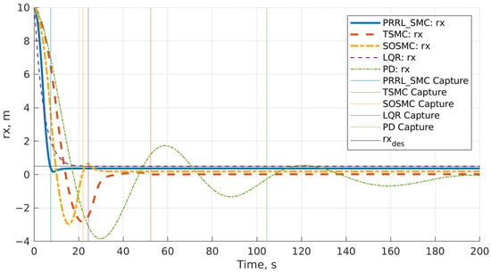
Figure 1.
Relative position—radial (x) component comparison.
Figure 2 shows the time history of the radial (x) component of the Chaser CubeSat’s relative velocity with respect to the debris object in the LVLH frame. The desired relative velocity for the RPO phase is zero. PRRL-SMC demonstrates the fastest capture time by bringing the relative velocity to zero most quickly.
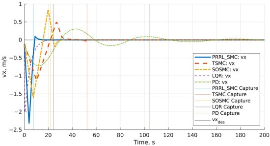
Figure 2.
Relative velocity—radial (x) component comparison.
Figure 3 presents the Chaser CubeSat’s angular velocities in the body frame along all axes during the pre-capture phase and shows the control effort from each controller to align with the debris.
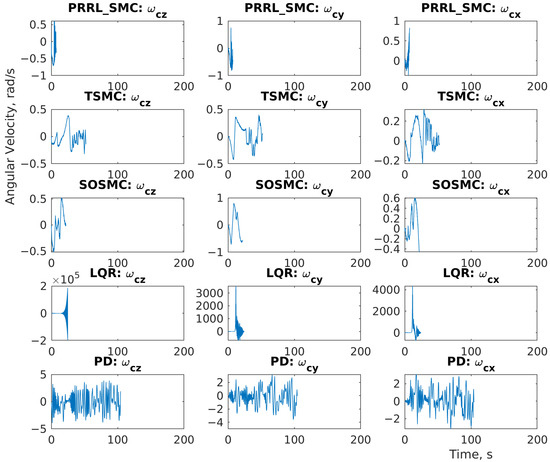
Figure 3.
Chaser angular velocity (body frame)—pre-capture (all axes).
Figure 4 shows the tumbling motion of the debris object, which the Chaser CubeSat’s control system must track for a successful capture maneuver.
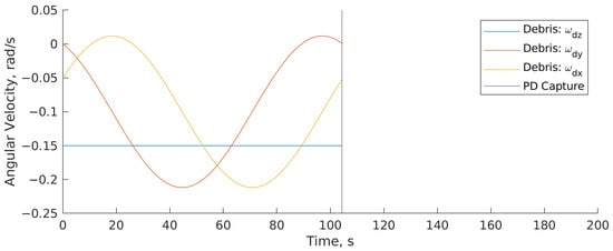
Figure 4.
Debris angular velocity (body frame).
Figure 5 shows how closely the Chaser CubeSat’s attitude tracks the debris’ attitude during the pre-capture phase.
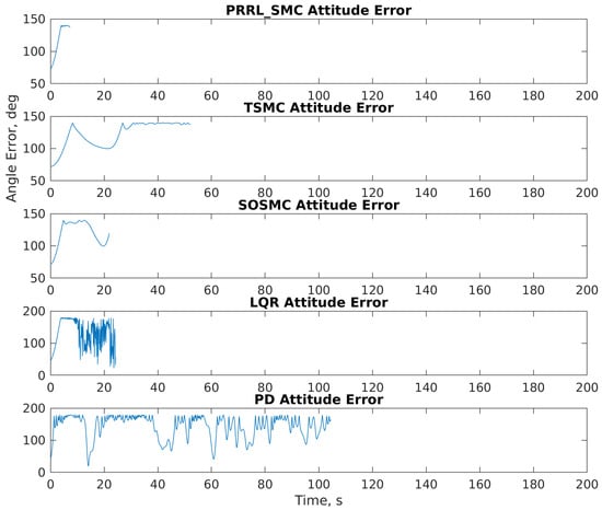
Figure 5.
Chaser attitude error (vs. debris attitude)—pre-capture.
Figure 6 shows the translational control force commanded by each controller along the X-axis in the LVLH frame. It allows for an evaluation of the control effort required by each method, subject to saturation limits. The errors are expected during the initial phase of the pre-capture maneuver because the Chaser CubeSat is actively working to track and align its attitude with the tumbling debris. The control systems eventually reduce these errors to zero to meet the capture threshold.
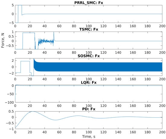
Figure 6.
Translational control force (LVLH frame)—Fx component.
Figure 7 shows the attitude control torque commanded by each controller along the X-axis in the body frame. The attitude control torques for the Y and Z axes in the body frame look similar and are not presented.
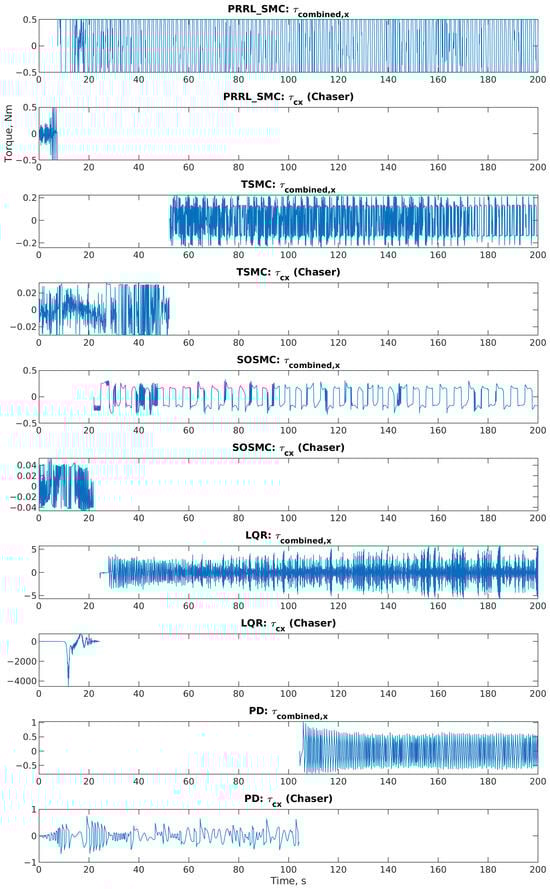
Figure 7.
Attitude control torque—X-axis (body frame).
5. Discussion
The simulation results clearly show that the Power Rate Reaching Law Sliding Mode Control (PRRL-SMC) reached the fastest capture time among the tested controllers. It significantly outperformed LQR (the second best). Such a rapid convergence is a consequence of the Power Rate Reaching law’s characteristic of generating larger control signals when the system state is further from the sliding surface.
The PD controller (which is simple to implement) showed the slowest capture time. This indicated the controller’s limitations in handling the complex dynamics and initial conditions of the debris capture scenario. LQR, however, provided a substantial improvement over PD, signifying the benefits of an optimal control approach for the linearized system. SOSMC and TSMC (as advanced SMC variants) also achieved capture faster than PD but were slower than LQR and PRRL-SMC in this specific simulation setup and with the chosen tuning parameters. The TSMC’s finite-time convergence property is theoretically appealing, but its performance is extremely reliant on the initial conditions as well as the parameter tuning.
The PRRL-SMC’s ability to achieve capture in only 7.6 s is particularly noteworthy for ADR missions where minimizing the time spent in proximity to a tumbling object can reduce fuel consumption. However, this aggressive performance comes at the cost of higher control effort, as seen in the control input plots. This is a limitation of the proposed work. The peak forces and torques commanded by the PRRL-SMC are higher than those of the other controllers. This happens as expected considering its faster convergence. The feasibility of implementing such a controller in a real CubeSat mission would depend on the capabilities and limitations of the available actuators (thrusters and reaction wheels).
Further tuning of the PRRL-SMC parameters and optimization of the sliding surface gains could further improve performance or balance capture speed with control effort. The choice of the power rate parameter α matters in the convergence speed because values closer to 0 lead to faster convergence when far from the surface but can increase chattering.
The simplified capture conditions and dynamics transition in this simulation are limitations. However, this comparative study offers solid evidence for the potential of PRRL-SMC in achieving rapid debris capture.
6. Conclusions
This paper presents a comparative study of various control strategies for CubeSat-based debris capture. The performance of Power Rate Reaching Law Sliding Mode Control (PRRL-SMC) was presented. The results showed that the PRRL-SMC controller achieved faster capture times compared to PD, LQR, SOSMC, and TSMC controllers. This shows the success of the Power Rate Reaching law in accelerating convergence to the desired state. While the PRRL-SMC asks for higher control authority, its ability to reach fast capture makes it a reliable time-sensitive active debris removal mission controller. The PRRL-SMC controller, here, showed faster capture times compared to the other methods. This controller achieved capture in 7.6 s, compared to LQR’s 24.6 s, SOSMC’s 28.1 s, TSMC’s 51.2 s, and PD’s 104.4 s. This shows the efficiency of PRRL-SMC for time-critical debris capture missions.
Future work can focus on further optimization of PRRL-SMC parameters, validation with more complex dynamics models, and consideration of actuator constraints and realistic sensor performance.
Author Contributions
Conceptualization, M.A. and A.M.O.; methodology, M.A. and A.M.O.; software, M.A.; validation, M.A. and A.M.O.; resources, M.A.; writing—original draft preparation, M.A.; writing—review and editing, M.A., A.M.O., and K.G.; visualization, K.G.; supervision, K.G.; project administration, M.A. and K.G.; funding acquisition, K.G. All authors have read and agreed to the published version of the manuscript.
Funding
This work was supported by the European Regional Development Fund under the “Research Innovation and Digitization for Smart Transformation” program 2021–2027 under the Project BG16RFPR002-1.014-0006 “National Centre of Excellence Mechatronics and Clean Technologies”.
Institutional Review Board Statement
Not applicable.
Informed Consent Statement
Not applicable.
Data Availability Statement
Data will be available on request.
Acknowledgments
This research was supported by the scientific research project No. 253CH0001-04 “Development of infrastructure and environment for aerospace education and research at TU-Sofia/INSATUS/” by the contract with “Research and development sector at TU-Sofia”.
Conflicts of Interest
The authors declare no conflicts of interest. The funders had no role in the design of the study; in the collection, analyses, or interpretation of data; in the writing of the manuscript; or in the decision to publish the results.
References
- Kessler, D.J.; Cour-Palais, B.G. Collision Frequency of Artificial Satellites: The Creation of a Debris Belt. J. Geophys. Res. 1978, 83, 2637–2646. [Google Scholar] [CrossRef]
- Bonnal, C.; Ruault, J.; Desjean, M. Active Debris Removal: Recent Progress and Current Trends. Acta Astronaut. 2013, 85, 51–60. [Google Scholar] [CrossRef]
- Shan, M.; Guo, J.; Gill, E. Review and Comparison of Active Space Debris Capturing and Removal Methods. Prog. Aerosp. Sci. 2016, 80, 18–32. [Google Scholar] [CrossRef]
- Bigdeli, M.; Srivastava, R.; Scaraggi, M. Mechanics of Space Debris Removal: A Review. Aerospace 2025, 12, 277. [Google Scholar] [CrossRef]
- Madikiza, L.D. Combatting Space Debris: Reviewing Challenges and Prospects. In Exploring Pillars of Sustainability for Modern Age Improvements; IGI Global Scientific Publishing: Hershey, PA, USA, 2025; pp. 45–64. [Google Scholar]
- WeFallahiarezoodar, N.; Zhu, Z.H. Review of Autonomous Space Robotic Manipulators for On-Orbit Servicing and Active Debris Removal. Space Sci. Technol. 2025, 5, 0291. [Google Scholar] [CrossRef]
- Woellert, K.; Ehrenfreund, P.; Ricco, A.J.; Hertzfeld, H.R. Cubesats: Cost-Effective Science and Technology Platforms for Emerging and Developing Nations. Adv. Space Res. 2011, 47, 663–684. [Google Scholar] [CrossRef]
- Shan, M.; Guo, J.; Gill, E. Contact dynamics on net capturing of tumbling space debris. J. Guid. Control Dyn. 2018, 41, 2063–2072. [Google Scholar] [CrossRef]
- Dubanchet, V.; Saussié, D.; Alazard, D.; Bérard, C.; Le Peuvédic, C. Modeling and Control of a Space Robot for Active Debris Removal. Ceas Space J. 2015, 7, 203–218. [Google Scholar] [CrossRef]
- Yang, Y. Analytic LQR Design for Spacecraft Control System Based on Quaternion Model. J. Aerosp. Eng. 2012, 25, 448–453. [Google Scholar] [CrossRef]
- Chen, R.; Dong, M.; Bai, Y.; Zhao, Y.; Chen, X. Trajectory planning and control of spacecraft avoiding dynamic debris swarm. Aerosp. Sci. Technol. 2024, 151, 109273. [Google Scholar] [CrossRef]
- Carer, C.; Mooij, E. Space debris collision avoidance manoeuvre design and analysis. In Proceedings of the AIAA SCITECH 2025 Forum, Orlando, FL, USA, 6–10 January 2025. [Google Scholar]
- Liu, Y.; Liu, X.; Cai, G.; Xu, F.; Tang, S. Orbit-attitude coupled dynamics modeling and adaptive sliding mode control for detumbling large space debris. Aerosp. Sci. Technol. 2024, 151, 109269. [Google Scholar] [CrossRef]
- Sampath, S.; Feng, J. Intelligent and robust control of space manipulator for sustainable removal of space debris. Acta Astronaut. 2024, 220, 108–117. [Google Scholar] [CrossRef]
- Azadmanesh, M.; Todorov, M.; Georgiev, K. Leveraging fuzzy logic for an asteroid mission: Introducing a new fuzzy algorithm. In the Proceedings of the 16th International Scientific Conference On Aeronautics, Automotive And Railway Engineering And Technologies: BulTrans-2024, Sozopol, Bulgaria, 10–13 September 2024. [Google Scholar]
- Azadmanesh, M.; Roshanian, J.; Hassanalian, M. Fast Terminal Sliding Mode Control for the Soft Landing of a Space Robot on an Asteroid Considering a Barycentric Gravitational Model. J. Aerosp. Sci. Technol. 2023, 16, 66–76. [Google Scholar]
- Azadmanesh, M.; Roshanian, J.; Georgiev, K.; Todrov, M.; Hassanalian, M. Synchronization of angular velocities of chaotic leader-follower satellites using a novel Integral Terminal Sliding Mode Controller. Aerosp. Sci. Technol. 2024, 150, 109211. [Google Scholar] [CrossRef]
- Devika, K.B.; Thomas, S. Power rate exponential reaching law for enhanced performance of Sliding Mode Control. International J. Control Autom. Syst. 2017, 15, 2636–2645. [Google Scholar]
- Wang, S.; Jiang, C.; Tu, Q.; Zhu, C. Sliding mode control with an adaptive switching power reaching law. Sci. Rep. 2023, 13, 16155. [Google Scholar] [CrossRef]
- Devika, K.B.; Thomas, S. Sliding mode controller design for MIMO Nonlinear Systems: A novel power rate reaching law approach for improved performance. J. Frankl. Inst. 2018, 355, 5082–5098. [Google Scholar] [CrossRef]
- Adamiak, K.; Bartoszewicz, A. Novel power-rate reaching law for quasi-sliding mode control. Energies 2022, 15, 5446. [Google Scholar]
- Ma, H.; Li, Y.; Xiong, Z. Discrete-time sliding-mode control with enhanced power reaching law. IEEE Trans. Ind. Electron. 2019, 66, 4629–4638. [Google Scholar]
- Clohessy, W.H.; Wiltshire, R.S. Terminal guidance system for satellite rendezvous. J. Aerosp. Sci. 1960, 27, 653–658. [Google Scholar] [CrossRef]
- Sprague, C.I. Modelling and simulation of autonomous cubesats for orbital debris mitigation. In Proceedings of the Sixth International Conference on Astrodynamics Tools and Techniques, ICATT, Darmstadt, Germany, 14–17 March 2016; European Space Agency: Darmstadt, Germany, 2016. [Google Scholar]
- Sherif, K.; Nachbagauer, K.; Steiner, W. On the rotational equations of motion in rigid body dynamics when using euler parameters. Nonlinear Dyn. 2015, 81, 343–352. [Google Scholar] [CrossRef]
Disclaimer/Publisher’s Note: The statements, opinions and data contained in all publications are solely those of the individual author(s) and contributor(s) and not of MDPI and/or the editor(s). MDPI and/or the editor(s) disclaim responsibility for any injury to people or property resulting from any ideas, methods, instructions or products referred to in the content. |
© 2026 by the authors. Licensee MDPI, Basel, Switzerland. This article is an open access article distributed under the terms and conditions of the Creative Commons Attribution (CC BY) license.