Abstract
This study investigates the development of adiabatic shear bands (ASBs) in AISI 1045 carbon steel under high-strain-rate uniaxial compression, emphasizing the conditions governing their onset and growth. Split Hopkinson pressure bar (SHPB) experiments were carried out at strain rates of 1000, 2000 and 4000 s−1 with controlled displacement/strain interruption to capture gradual ASB formation throughout the process. Stress–strain data were analyzed alongside optical microscopy to determine the critical strain for ASB initiation, document ASB morphology, dimensions and type, and connect ASB formulating stages to material macroscopic mechanical behavior. The observations clarify how deformation evolves from homogenous plastic flow to localized shear instability as the strain and strain rate increase, linking mechanical response to microstructural features. Integrating these results, the effects of strain rate and strain progress on ASB formation and evolution characteristics are investigated. These findings enhance our understanding of shear localization phenomena under dynamic loading and provide a basis for predicting failure modes in structural applications.
1. Introduction
High-strain-rate metal deformation can create instability, manifesting as stress–strain curve decrease and adiabatic shear banding (ASB) formation. Intense shear is localized within narrow zones (tens to hundreds of micrometers) and provides highly localized plastic work, which is partially converted to internal heat according to Taylor–Quinney coefficient [1]. Limited heat diffusion at high strain rates creates adiabatic conditions, trapping heat and causing thermal softening that may trigger phase transformation or recrystallization, degrading mechanical properties. When thermal softening exceeds strain and strain rate hardening, instability occurs, which coincides with ASB onset, providing a macroscopic criterion for ASB initiation. ASBs manifest as two types: deformed bands show severe shear localization with elongated/fragmented grains, while transformed bands exhibit phase transformation or recrystallization with higher hardness due to quenching that can follow when the deformation stops or/and ultrafine grains are formed [2]. The transformation requires a sufficient temperature rise for microstructural changes and usually rapid cooling that follows after the deformation. Both band types represent thermomechanical instability where localized shear and thermal effects determine microstructural evolution and mechanical properties [2,3]. Therefore, ASBs are important in the manufacturing industry due to their direct impact on material plasticity and failure, especially at high strain rates, and so their better understanding allows the design of efficient manufacturing processes with respect to tool design, process parameters, and material selection, aiming to predict and control the ASB mechanism.
Regarding ASB development in uniaxial compression of cylindrical specimens, Odeshi and Bassim [4] demonstrated that adiabatic heating and thermal softening drive unstable deformation in AISI 4340 steel, forming parabolic ASBs with S-shaped fracture paths and knobby features indicating local melting. Odeshi et al. [5] observed parabolic martensitic ASB cones in AISI 4340 cylinders, with micropore coalescence causing 45° crack propagation. Martensitic steels showed higher ASB resistance than dual-phase steels due to more homogeneous deformation [6]. Lee et al. [7] found that increased carbon content in steels produced narrower, hotter ASBs with greater hardness, while higher strain rates decreased ASB width. Low-carbon steels formed only deformed ASBs, whereas medium and high-carbon steels developed both deformed and martensitic transformed ASBs. Kang et al. [8] showed that higher pearlite content facilitates ASB formation in carbon steels (0.2–0.8% C), with 0.8C steel developing white-colored transformed ASBs with 45° cracking. Syn et al. [9] reported 44 μm wide ASBs in 1.3% C steel initiating at 55% strain, with austenitic transformation and retransformation providing high core hardness.
This research experimentally examines the ASB development in AISI 1045 carbon steel under dynamic uniaxial compression through microstructural observations and material mechanical behavior to capture the ASB initiation and evolution. Split Hopkinson pressure bar (SHPB) testing at strain rates of 1000–2000–4000 s−1 under controlled strain interruption was conducted, aiming to distinguish the deformation progression from uniform plastic flow to localized shear instability. Evaluating the stress–strain response and optical microscopy samples, this work aims to investigate the development of the ASB mechanism during deformation, connecting the microstructural evolution with the macroscopic mechanical material behavior. The macroscopic viewpoint relates the ASB initiation to the stress–strain instability which takes place when softening effects like thermal or/and microstructural effects overcome strain hardening, reacting to the instability point in stress–strain curve (dσ/dε 0) [2,10]. Finally, the ASB width, the intensity of shear strain through the curvature of plastic flow lines and the elongation of grains inside ASB are evaluated together with the strain instability in order to highlight the effect of strain rate and strain on ASB generation.
2. Materials and Methods
This work studies the dynamic compression of AISI 1045 medium carbon steel using cylindrical specimens with 6 mm height and diameter, while different strain rates of 1000–2000–4000 s−1 and strains were examined as shown in Table 1. The desired strain is achieved using a stopper ring of proper height, while the final compressive test is conducted without a ring in order to reach the maximum possible strain. In fact, 1000 s−1 strain rate included only the one test carried out without stopper ring. The specimens were made from a hot-rolled round 1045 steel bar, so that the loading direction coincided with the rolling direction. The tests were carried out with a SHPB system, as depicted in Figure 1 [11]. The system consists of a striker, an incident and a transmitted bar. All bars were made of maraging steel with 22 mm in diameter. The incident and transmitted bars were 1.2 m long, while the length of striker bar 400–300–200 mm varied for each strain rate of 1000–2000–4000 s−1, respectively. The experimental equipment is located at Tampere University. The striker bar is accelerated by compressed air, impacting the free end of the incident bar, while the specimen-stopper ring assembly is already placed between the incident and the transmitted bar. The impact of the striker with the free end of the incident bar creates a compressive stress pulse that travels along the incident bar and finally passes through the specimen into the transmitted bar. As the stress pulse travels through the bars and the specimen is compressed at a high rate. Two strain gage stations (half bridge) were used to measure strains in the bars. A molybdenum disulfide (MOS2) layer with a solid lubricant was used to minimize friction and avoid barreling at bar–specimen interfaces. Finally, the stress–strain curve is calculated from the strain gage measurements according to one-dimensional wave propagation theory as shown, for example, in [12].

Table 1.
Strain and strain rate for each test.
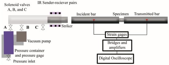
Figure 1.
Schematic picture of the Split Hopkinson pressure bar (SHPB) system [11].
3. Results and Discussion
The specimen deformed at the strain rate of 1000 s−1, whose stress—strain curve is shown in Figure 2, did not reveal any ASB formation at the maximum strain of 15%. Only homogeneous deformation and stable plastic flow were detected in the optical micrographs of the deformed cross-section depicted in Figure 3.
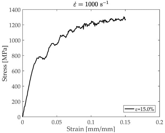
Figure 2.
Experimental stress–strain curve for test 1 at strain rate of 1000 s−1.
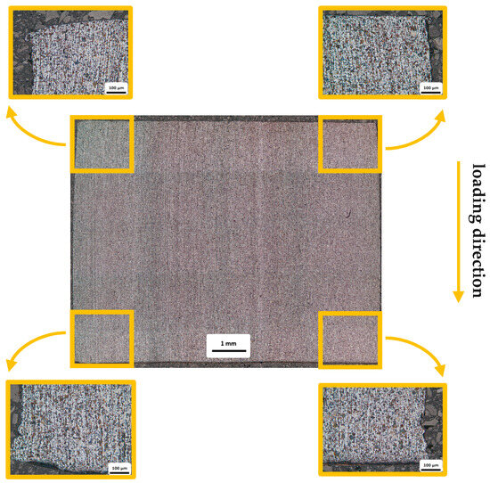
Figure 3.
Optical micrographs of the specimen deformed to 15% strain at strain rate of 1000 s−1.
The optical micrographs obtained from the specimens deformed at a 2000 s−1 strain rate to 18% and 20% strain did not show any shear localization. The deformed structure was dominated by stable and homogenous plastic deformation. In fact, the grey and purple stress–strain curves in Figure 4 present continuous hardening until the end of the experiment at approximately 20% of strain. Figure 5 shows the structure of the specimen deformed to 26% strain (black stress–strain curve of Figure 4) where deformed ASBs (dASBs) are visible around the top corners of the specimen, which are indicated through the curvature of plastic flow lines showing shear localization. The top left dASB seems stronger than the top right one due to more intensely curved and elongated flow lines. Both bands propagate almost diagonally.
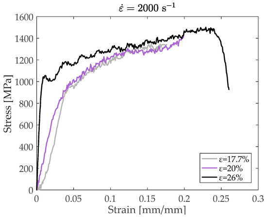
Figure 4.
Stress–strain curves for tests 1–2–3 at the strain rate of 2000 s−1.
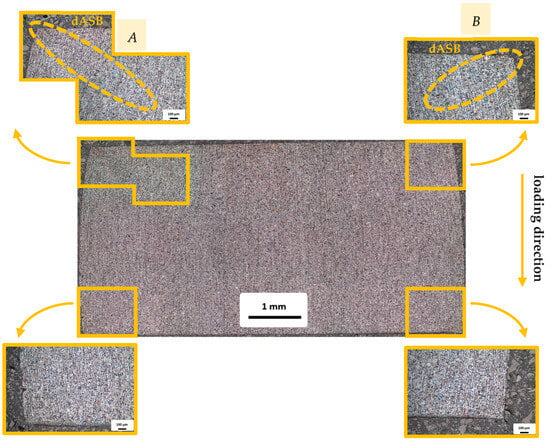
Figure 5.
Optical micrographs of deformed specimen at 26% strain and 2000 s−1 strain rate.
Figure 6 shows in more detail that the dASBs (in Figure 5) form more severely around the corners and weaken as they propagate diagonally towards the sample center. Also, the two bands show similar width of 76 μm (top left) and 72 μm (top right) transversely to the ASB direction, with the top left band seeming to be significantly stronger in magnitude due to more intensely curved flow lines, but slightly wider than the top right band.
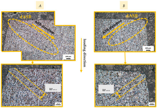
Figure 6.
Zoomed views of A and B specimen corners at 26% strain and 2000 s−1 strain rate.
The microstructures of the specimens deformed at the strain rate of 4000 s−1 to 13% and 21% strains did not show any shear localization and the grey and purple stress–strain curves in Figure 7 showed only continuous hardening. Figure 8 illustrates the optical micrographs of the sample deformed to 30.75% strain, where again two dASBs form around specimen top corners. In fact, the ASB formation can be detected even from the overall sample view focusing on the darker areas around top corners (marked in the dashed elliptical areas) which indicate shear localization coming from the intense curvature of the plastic flow lines. Again, the top left dASB seems slightly stronger in magnitude, but both bands extend at similar length in contrast to the 2000 s−1 strain rate.
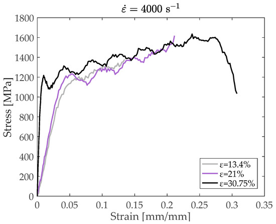
Figure 7.
Stress–strain curves for tests 1–2–3 at strain rate of 4000 s−1.
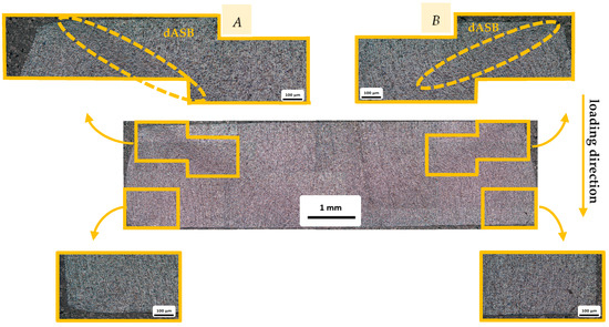
Figure 8.
Optical micrographs of deformed specimens with 30.75% strain and at 4000 s−1 strain rate.
Figure 9 shows in more detail the deformed microstructure around top corners for 30.75% strain at the 4000 s−1 strain rate. The results indicate that the top left dASB is wider than the top right one with ASB widths of 177 μm and 115 μm, respectively. A comparison between the tests 3 at 2000 and 4000 s−1 strain rates shows that the higher strain and strain rate of the test 3 at 4000 s−1 seems to provide wider bands with greater shear strain and a more intense elongation of grains due to the longer ASB evolution and its widening as well as the higher strain rate, which further promotes ASB formation by enhancing adiabatic conditions and thermal softening.
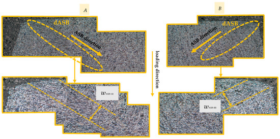
Figure 9.
Zoomed views of A and B specimen corners at 30.75% strain and 4000 s−1 strain rate.
4. Conclusions
The current work experimentally studied the ASB formation in 1045 carbon steel subjected to high-strain-rate uniaxial compression using SHPB tests and microstructural examination. The orientation change in the plastic flow lines was used to recognize the shear localization regions, which were detected from the S-shape trajectories of the flow lines.
The microstructural analysis showed no ASBs at the lowest strain rate, while dASBs were identified in the top corners of the specimens deformed at both 2000 and 4000 s−1 strain rates. In both cases, the top left band seemed stronger in magnitude and wider compared to the top right band, which was even more obvious at the strain rate of 4000 s−1. In more detail, the specimen deformed at the strain rate of 2000 s−1 showed two dASBs of almost the same width, but the left one expanding along longer path, while at the strain rate of 4000 s−1, the specimen deformed two dASBs of similar length but of higher difference in width. In fact, the dASBs observed in the specimens deformed at 4000 s−1 strain rate showed significant graining elongation inside their core. However, the amount of deformation in the specimens was not exactly the same, so the conclusions presented here are tentative.
Author Contributions
Conceptualization, K.K., M.H. and D.M.; methodology, K.K. and M.H.; software, J.R. and M.H.; validation, K.K., J.R. and D.M.; formal analysis, K.K. and J.R.; investigation, K.K. and J.R.; resources, M.H.; data curation, J.R. and M.H.; writing—original draft preparation, K.K.; writing—review and editing, K.K.; visualization, K.K. and J.R.; supervision, M.H. and D.M.; project administration, M.H.; funding acquisition, M.H. All authors have read and agreed to the published version of the manuscript.
Funding
The research work was supported by the Hellenic Foundation for Research and Innovation (HFRI) under the 4th Call for HFRI PhD Fellowships (Fellowship Number: 10838).
Institutional Review Board Statement
Not applicable.
Informed Consent Statement
Not applicable.
Data Availability Statement
The data can be made available upon reasonable request to the corresponding author.
Acknowledgments
This work made use of the Split Hopkinson bar laboratory facilities at Tampere University.
Conflicts of Interest
The authors declare no conflicts of interest.
References
- Rittel, D.; Zhang, L.; Osovski, S. The Dependence of the Taylor–Quinney Coefficient on the Dynamic Loading Mode. J. Mech. Phys. Solids 2017, 107, 96–114. [Google Scholar] [CrossRef]
- Karantza, K.D.; Manolakos, D.E. A Review on the Adiabatic Shear Banding Mechanism in Metals and Alloys Considering Microstructural Characteristics, Morphology and Fracture. Metals 2023, 13, 1988. [Google Scholar] [CrossRef]
- Karantza, K.D.; Manolakos, D.E. A summary on the microstructural characteristics of adiabatic shear bands and their experimental observation methods. In Proceedings of the 39th Danubia-Adria Symposium on Advances in Experimental Mechanics (39th DAS), Siofok, Hungary, 26–29 September 2023. [Google Scholar]
- Odeshi, A.G.; Bassim, M.N. High Strain-Rate Fracture and Failure of a High Strength Low Alloy Steel in Compression. Mater. Sci. Eng. A 2009, 525, 96–101. [Google Scholar] [CrossRef]
- Odeshi, A.G.; Bassim, M.N.; Al-Ameeri, S.; Li, Q. Dynamic Shear Band Propagation and Failure in AISI 4340 Steel. J. Mater. Process. Technol. 2005, 169, 150–155. [Google Scholar] [CrossRef]
- Odeshi, A.G.; Bassim, M.N. Evolution of Adiabatic Shear Bands in a Dual-Phase Steel at Very High Strain Rates. Mater. Sci. Eng. A 2008, 488, 235–240. [Google Scholar] [CrossRef]
- Lee, W.-S.; Liu, C.-Y.; Chen, T.-H. Adiabatic Shearing Behavior of Different Steels under Extreme High Shear Loading. J. Nucl. Mater. 2008, 374, 313–319. [Google Scholar] [CrossRef]
- Kang, M.; Park, J.; Sohn, S.S.; Kim, H.; Kim, K.-H.; Lee, S. Adiabatic Shear Banding and Cracking Phenomena Occurring during Cold-Forging Simulation Tests of Plain Carbon Steel Wire Rods by Using a Split Hopkinson’s Pressure Bar. Met. Mater. Int. 2015, 21, 991–999. [Google Scholar] [CrossRef]
- Syn, C.K.; Lesuer, D.R.; Sherby, O.D. Microstructure in Adiabatic Shear Bands in a Pearlitic Ultrahigh Carbon Steel. Mater. Sci. Technol. 2005, 21, 317–324. [Google Scholar] [CrossRef]
- Yan, N.; Li, Z.; Xu, Y.; Meyers, M.A. Shear Localization in Metallic Materials at High Strain Rates. Prog. Mater. Sci. 2021, 119, 100755. [Google Scholar] [CrossRef]
- Tampere University. Compression SHPB [Online Image]. 2025. Available online: https://research.tuni.fi/impact/equipment/454-2/ (accessed on 27 October 2025).
- Li, X.-Y.; Zhang, Z.-H.; Cheng, X.-W.; Wang, Q.; Jia, X.-T.; Wang, D.; Wang, X.-F. The evolution of adiabatic shear band in high Co–Ni steel during high strain-rate compression. Mater. Sci. Eng. A 2022, 858, 144173. [Google Scholar] [CrossRef]


Disclaimer/Publisher’s Note: The statements, opinions and data contained in all publications are solely those of the individual author(s) and contributor(s) and not of MDPI and/or the editor(s). MDPI and/or the editor(s) disclaim responsibility for any injury to people or property resulting from any ideas, methods, instructions or products referred to in the content. |
© 2025 by the authors. Licensee MDPI, Basel, Switzerland. This article is an open access article distributed under the terms and conditions of the Creative Commons Attribution (CC BY) license.