Abstract
This study investigates the correlation between strains obtained from the image-based technique GeoPIV and Fiber Bragg Grating (FBG) sensors’ measurements in Mechanically Stabilized Earth (MSE) systems, using scaled physical modeling in a geotechnical centrifuge. FBG sensors provide high-resolution, localized strain data along reinforcements, while GeoPIV offers full-field visualization of soil deformation. By calibrating GeoPIV outputs to microstrains, the complementary strengths of the two approaches are highlighted. In addition, the centrifuge setup reproduces realistic stress conditions, enhancing experimental reliability. The combined use of these methods not only improves understanding and monitoring of MSE behavior but also demonstrates strong potential for broader application in other laboratory-scale studies.
1. Introduction
Structural and vulnerability assessment in geotechnical engineering is commonly approached through numerical/computational modeling, structural monitoring, and physical modeling. Numerical analyses, often based on the finite element method, allow for the prediction of stress–strain behavior under a wide range of loading scenarios. Structural monitoring, performed either on site or in laboratory conditions, provides direct measurements of system performance. Physical modeling, carried out at reduced or full scales, enables the controlled investigation of soil–structure interaction mechanisms under defined boundary conditions. As presented in Figure 1, these approaches can provide complementary insights that improve the reliability of hazard evaluation and structural response prediction. The integration of methods enhances both research outcomes and practical decision-making in geotechnical engineering.
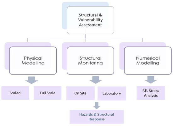
Figure 1.
Integrated approach to structural and vulnerability assessment.
Physical modeling, particularly at reduced scales, plays an important role in advancing understanding of complex engineering systems where full-scale testing is either impractical or cost-prohibitive. Among available tools, geotechnical centrifuge modeling provides an advantage by allowing scaled physical models to replicate in situ stress conditions through increased gravitational acceleration. This enables realistic simulation of stress-dependent behavior in soil–structure systems, including strain localization, reinforcement–soil interaction, and deformation mechanisms, thereby offering valuable insight into the performance of geotechnical structures under various loading scenarios [1].
Strain measurement within these physical models remains a critical challenge. Fiber Bragg Grating (FBG) sensors, offer high-resolution, multiplexed, and durable strain measurements along the reinforcement, enabling precise monitoring of tensile strain distribution under controlled loading conditions. These sensors are especially suitable for centrifuge applications, where space constraints and harsh environments necessitate compact instrumentation [2]. Complementing the point-based nature of optical sensing, image-based measurement techniques, such as Particle Image Velocimetry (PIV) and its geotechnical adaptation GeoPIV [3,4], have emerged as powerful tools for non-invasive, full-field deformation analysis. GeoPIV enables the quantification of soil displacement and strain fields by tracking patterns within sequential digital images, offering spatially continuous data that are otherwise inaccessible through conventional instrumentation.
Within the context of soil-structure interaction, Mechanically Stabilized Earth (MSE) systems, comprising compacted soils reinforced with tensile elements such as geosynthetics or metallic strips, have become integral to geotechnical infrastructure. Their widespread adoption is due to their enhanced load-bearing capacity and seismic resilience. Central to the performance of MSE systems is the interaction between soil and reinforcement, wherein the soil provides shear and compressive resistance, while the reinforcement contributes tensile strength. The objective of this study is to examine the correlation between normalized strain data derived from GeoPIV analysis and strain measurements obtained from FBG sensors embedded within reinforcement layers in a centrifuge-scale MSE model. By calibrating the image-based strain data against localized optical sensor readings, this research aims to evaluate the consistency and potential complementarity of these methods in the context of physical modeling. The findings contribute to the refinement of experimental methodologies for soil–reinforcement systems and suggest a broader applicability of this integrated measurement approach in laboratory-scale investigations of geotechnical behavior.
2. Physical Modeling and Structural Monitoring
In engineering, physical modeling is particularly important when prototype behavior is not fully understood or requires detailed investigation. It allows for the study of deformation mechanisms, identification of failure modes, and generation of data for comparison with analytical and numerical models. In geotechnical engineering, one key challenge is replicating self-weight stresses in reduced-scale models, as gravitational forces do not scale directly. To address this limitation, geotechnical centrifuge modeling applies enhanced gravitational acceleration, enabling stress distributions in the model to reproduce those of the prototype. First applied in the 1930s by Bucky and Pokrovsky, centrifuge modeling has since become a powerful research tool worldwide [5,6].
Centrifuge technology includes two main configurations: beam centrifuges, with models mounted in a rotating basket, and drum centrifuges, which allow easier access and load adjustments. The method relies on scaling laws that define how parameters such as stress, force, time, and particle size scale with the model factor [7]. Proper material selection is essential, particularly for soils and reinforcement elements, which must satisfy both geometric and mechanical similarity. Despite challenges in reproducing certain materials such as geosynthetics, centrifuge modeling remains one of the most reliable approaches for studying soil–structure interaction under realistic stress conditions.
Specialized sensors, such as those measuring pore water pressure, soil saturation, or strain, are selected based on the specific variables of interest. Careful attention must be given not only to the choice of sensors but also to the methods of data acquisition and storage. While earlier technological limitations hindered real-time recording during centrifuge operation, modern computing capabilities now allow data to be efficiently captured both on-site and remotely. Additionally, the size and weight of sensors must be minimized to avoid influencing the behavior of the model, as bulky components, such as thick cables, can inadvertently alter the structural or soil response.
Over the past decades, FBG optical sensors have been used widely for their microstrain precision, mechanical robustness, multiplexing capability, and compact size [8,9,10,11]. Their small form allows installation at critical points in experimental models of various scales, providing detailed strain data. In this study, FBG sensors were embedded in reinforcement layers of slope models in a geotechnical centrifuge, with attention to installation and data acquisition to ensure measurements without affecting model behavior.
On the other hand, image-based techniques have long been used to measure shear strains in geotechnical experiments, evolving from early X-ray methods to stereophotogrammetry and modern digital image processing. These methods rely on markers within the soil as reference points, with accuracy depending on detection algorithms and calibration. In this study, PIV and the GeoPIV adaptation were used to track displacement and shear strain in centrifuge models [12]. GeoPIV exploits natural soil texture, dividing images into patches tracked across frames to generate full strain fields, with calibration converting pixel measurements into real-world units. The approach provides a reliable, non-intrusive means of capturing detailed soil deformation.
Building on these experimental and monitoring techniques, the study investigates the correlation between normalized strain measurements obtained from image-based methods and data recorded by FBG optical sensors in MSE systems.
3. Laboratory Testing and Recordings
Scaled MSE slope models were constructed within strong boxes with internal dimensions of 40 × 40 × 20 cm. One vertical side was made of transparent Plexiglas to enable observation and measurement of soil displacements, with a printed grid applied to facilitate PIV analysis. The models were built with white, fine-grained sand, characterized by an internal friction angle of 33° which was deposited via controlled pluviation to achieve uniform density and had total height of 18 cm and slope inclination at 2V:1H.
FBG sensors by FOS&S (Geel, Belgium) were embedded within the reinforcement layers to monitor strain development under increasing g-level, with 5 sensors glued on 2 reinforcement layers (layers 4 and 8), bonded using UV-curing adhesive combined with powder–liquid mixtures to ensure full contact and prevent slippage. Each sensor had a distinct initial Bragg wavelength within the 1527–1567 nm range. The sensors were connected in series, enabling simultaneous strain measurements through a portable interrogator during centrifuge operation. Dynamic loading was included by releasing scaled boulder models onto the slopes, while enhanced gravitational acceleration reproduced prototype stress conditions. Additionally, high-speed imaging facilitated PIV analysis, providing full-field visualization of soil displacement and strain evolution. Strain distributions from GeoPIV were obtained for different g-levels, allowing characterization of deformation patterns and were compared to localized measurements recorded by the optical fiber sensors.
Figure 2a shows indicative optical fiber recordings from a centrifuge test, where wavelength shifts from the FBG sensors are converted to strain. During this test, the g-level was increased in 5 g increments every 2 min up to 50 g, followed by unloading and immediate reloading to 50 g. The sensor recordings clearly distinguish between stepwise and direct loading, showing that maximum strains were smaller under direct loading, highlighting the influence of loading history on strain development. After the second 50 g load, a model boulder was released at the slope crest, which is clearly visible in the optical fiber recordings, and the resulting transient strains were captured. Sensors positioned near the crest and at mid-slope indicate that the largest strains occur mid-slope, attributed to the increased soil overburden and stress redistribution along the reinforcement layers. Figure 2b illustrates a different loading sequence: direct loading to 50 g, boulder release, and subsequent increase to 100 g. Despite the altered procedure, the recorded strain patterns are consistent with those in (a), demonstrating reliable sensor performance and reproducible slope response under varying loading conditions. These results highlight the ability of the FBG sensors to capture both gradual and dynamic strain changes, providing detailed insight into slope behavior under complex loading scenarios.
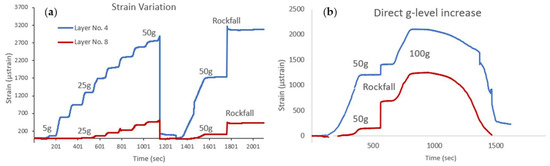
Figure 2.
Indicative optical fiber strain recordings showing loading sequences: in 5 g increments every 2 min (a) and direct loading (b).
Figure 3 shows indicative strain distributions obtained via GeoPIV at g-levels of 5, 25, and 50, in ‘GeoPIV strain units’. Highest strains occur near the eventual slope failure zone, consistent with observed failure and classical mechanisms such as Bishop surfaces. Strain magnitudes increase with g-level, with elevated values near the slope toe and lower front, especially under saturated conditions. Correspondent optical fiber sensor positions are indicated with the red vectors. These data form the basis for a quantitative comparison between the image-based GeoPIV measurements and the localized strains recorded by the optical fibers, which is analyzed in the following section.
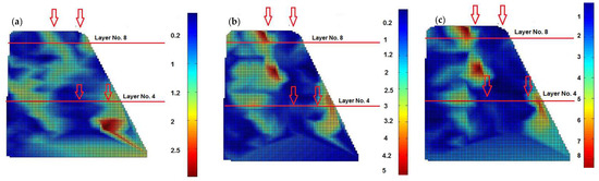
Figure 3.
Strain distributions from GeoPIV at g-levels 5 (a), 25 (b), and 50 (c), with red vectors indicating sensor positions.
4. Correlation of Normalized Strain from GeoPIV with Optical Fiber Sensors
This section focuses on establishing a correlation between strain measurements obtained via GeoPIV (presented in ‘GeoPIV strain units’) and strains recorded by optical fiber sensors. As aforementioned, while GeoPIV provides full-field deformation data across the model, its output is initially expressed in relative or normalized units that do not directly represent physical strain. To enable a quantitative comparison, the normalized GeoPIV strains at locations adjacent to the FBG sensors are scaled based on the corresponding optical fiber readings, calibrating the image-based data. This approach allows the conversion of GeoPIV-derived strain indicators into real strain values (µstrain), bridging the gap between localized sensor readings and full-field observations. By applying this calibration, it becomes possible to analyze the spatial distribution of actual strain within the soil model, capturing both the local reinforcement response recorded by the fibers and the broader deformation patterns highlighted by GeoPIV.
Table 1 summarizes indicative strain values derived from GeoPIV at locations aligned with the optical fiber sensors, for two separate tests involving g-levels up to 50 g and 100 g and for the two reinforcement layers (No. 4 and No. 8). In the first test, the g-level was progressively increased in 5 g increments every two minutes, while in the second test the model was directly subjected to 50 g and 100 g. Table 2 presents the corresponding optical fiber measurements for the same two tests.

Table 1.
Indicative strain values from GeoPIV (in GeoPIV strain units) at locations aligned with the optical fiber sensors, for tests under different centrifuge loading increments.
Table 2.
Indicative strain values (in μstrain) from optical fiber sensors, for tests under different centrifuge loading increments.
Based on these measurements, empirical correlations were established to convert GeoPIV strain units into predicted FBG strains. For this purpose, average GeoPIV strains at locations corresponding to the average FBG sensor positions were used to derive layer-specific calibration equations. It should be emphasized that the g-level has been incorporated into Equations 1 and 2, as it directly influences strain development and eventual failure. These Equations show good agreement with the experimental data across all g-levels and both tests, with deviations typically below 3%. By applying these calibrations, full-field GeoPIV measurements can be translated into quantitative predictions of local reinforcement strain, enabling a comprehensive assessment of both layer-specific behavior and overall soil deformation within the MSE system. Table 3 illustrates the application of the above Equations by comparing recorded and calculated FBG strains.
Table 3.
Validation of empirical correlations by comparing recorded and calculated FBG strains using GeoPIV data.
Figure 4 also presents a comparison of recorded and calculated FBG strains, validating the empirical correlations. It should be noted that FBG strain is not determined solely by the gravitational acceleration g. Both equations incorporate the term GeoPIVavg, indicating that the predicted strain also depends on the average GeoPIV value, which varies between experiments even at the same g-level, due to the different centrifuge loading scheme. In addition, variations are noted between Layer No. 4 and Layer No. 8, reflecting differences in mechanical behavior associated with sensor depth.
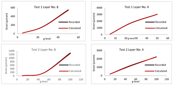
Figure 4.
Comparison of recorded and calculated FBG strains, illustrating the validation of the empirical correlations.
5. Conclusions
This study demonstrates the effective correlation between strain measurements obtained from image-based GeoPIV analysis and FBG optical sensors in centrifuge-scale MSE slope models. By calibrating normalized GeoPIV outputs against localized FBG readings, full-field deformation data were successfully converted into quantitative microstrain values. This calibration enabled a comprehensive assessment of both reinforcement layer-specific responses and the overall soil deformation behavior under increasing g-levels.
The results show close agreement between the two measurement methods, with deviations typically below 3%. This level of accuracy confirms the reliability of empirical correlations developed in this study and validates the use of image-based strain fields as a quantitative complement to optical sensing. Furthermore, findings highlight that strain development is not governed by gravitational acceleration alone; rather, it is strongly influenced by local soil–reinforcement interactions, sensor depth, and loading history. These factors emphasize the need to combine both localized and distributed measurement techniques when evaluating geotechnical systems.
Beyond the immediate scope of MSE slopes, the methodology presented here carries broader significance for experimental geomechanics. The combined use of FBG sensors and image-based techniques has strong potential in applications such as embankment stability assessment, retaining wall performance, foundation–soil interaction studies, and seismic response analysis. The ability to translate normalized, full-field image data into physical strain values greatly expands the utility of optical image processing in laboratory-scale geotechnical investigations.
Nevertheless, certain limitations should be acknowledged. The empirical correlations derived are specific to the materials, geometry, and loading protocols of the present centrifuge models. Future work should explore their transferability across different soil types, reinforcement configurations, and environmental. Additionally, the incorporation of higher-density distributed optical fiber sensing technologies alongside GeoPIV could further refine the resolution of strain mapping.
Author Contributions
Conceptualization, E.K.; methodology, E.K.; software, E.K.; investigation, E.K.; resources, A.S.; writing—original draft preparation, E.K.; writing—review and editing, E.K.; supervision, A.S. All authors have read and agreed to the published version of the manuscript.
Funding
This research received no external funding.
Institutional Review Board Statement
Not applicable.
Informed Consent Statement
Not applicable.
Data Availability Statement
The data presented in this study are available on request from the corresponding author.
Conflicts of Interest
The authors declare no conflicts of interest.
Abbreviations
The following abbreviations are used in this manuscript:
| FBG | Fiber Bragg Grating |
| MSE | Mechanically Stabilized Earth |
| PIV | Particle Image Velocimetry |
References
- Springman, S.M.; Laue, J.; Boyle, R.; White, J.; Zweidler, A. The ETH Zurich geotechnical drum centrifuge. Int. J. Phys. Model. Geotech. Eng. 2001, 1, 59–70. [Google Scholar]
- Kapogianni, E.; Sakellariou, M.; Laue, J. Experimental Investigation of Reinforced Soil Slopes in a Geotechnical Centrifuge, with the Use of Optical Fibre Sensors. Geotech. Geol. Eng. 2017, V35, 585–605. [Google Scholar] [CrossRef]
- White, D.; Take, W.; Bolton, M. Measuring soil deformation in geotechnical models using digital images and PIV analysis. In Proceedings of the 10th International Conference on Computer Methods and Advances in Geomechanics, Tucson, AZ, USA, 7–12 January 2001; pp. 997–1002. [Google Scholar]
- Adrian, R.J. Particle imaging techniques for experimental fluid mechanics. Annu. Rev. Fluid Mech. 1991, 23, 261–304. [Google Scholar] [CrossRef]
- Bucky, P.B. The Use of Models for the Study of Mining Problems; Technical Publication 425; American Institute of Mining and Metallurgical Engineering: New York, NY, USA, 1931. [Google Scholar]
- Pokrovsky, G.Y.; Fedorov, I.S. Studies of soil pressures and soil deformations by means of a centrifuge. In Proceedings of the 1st International Conference on Soil Mechanics & Foundation Engineering, Cambridge, MA, USA, 22–26 June 1936; Casagrande, A., Rutledge, P.C., Eds.; Harvard University: Cambridge, MA, USA, 1936; pp. 1–70. [Google Scholar]
- Schofield, A. Cambridge geotechnical centrifuge operations. Geotechnique 1980, 30, 227–268. [Google Scholar] [CrossRef]
- Kechavarzi, C.; Soga, K.; De Battista, N.; Pelecanos, L.; Elshafie, M.; Mair, R. Distributed Fibre Optic Strain Sensing for Monitoring Civil Infrastructure; Institute of Civil Engineering Publishing: London, UK, 2016. [Google Scholar]
- Bado, M.F.; Casas, J.R. A Review of Recent Distributed Optical Fiber Sensors Applications for Civil Engineering Structural Health Monitoring. Sensors 2021, 21, 1818. [Google Scholar] [CrossRef] [PubMed]
- Minardo, A.; Zeni, L.; Coscetta, A.; Catalano, E.; Zeni, G.; Damiano, E.; De Cristofaro, M.; Olivares, L. Distributed Optical Fiber Sensor Applications in Geotechnical Monitoring. Sensors 2021, 21, 7514. [Google Scholar] [CrossRef] [PubMed]
- Arslan, K.; Kelam, M.; Eker, A.; Akgun, H.; Kockar, M. Optical Fiber Technology to Monitor Slope Movement. In Engineering Geology for Society and Territory; Springer: Cham, Switzerland, 2015; Volume 2, pp. 1425–1429. [Google Scholar]
- Kapogianni, E.; Laue, J.; Sakellariou, M. Reinforced slope modelling using optical fibre sensors and PIV analysis. In Physical Modeling in Geotechnics; Springman, S.M., Laue, J., Seward, L., Eds.; Taylor & Francis Group: Abingdon, UK, 2010. [Google Scholar]


Disclaimer/Publisher’s Note: The statements, opinions and data contained in all publications are solely those of the individual author(s) and contributor(s) and not of MDPI and/or the editor(s). MDPI and/or the editor(s) disclaim responsibility for any injury to people or property resulting from any ideas, methods, instructions or products referred to in the content. |
© 2025 by the authors. Licensee MDPI, Basel, Switzerland. This article is an open access article distributed under the terms and conditions of the Creative Commons Attribution (CC BY) license (https://creativecommons.org/licenses/by/4.0/).