Abstract
Fiber-reinforced plastics (FRP) have been established as spring materials for specific applications for decades. In addition to their material advantages, the associated characteristics of strength and stiffness loss due to fatigue and degradation must also be considered. For FRP springs, the stiffness loss gains importance because of functional relevance. This article focusses on the lifetime design of FRP springs from this perspective, based on the assumption that a service range develops over time and load cycles in which the spring exhibits the desired functional characteristics. This approach was investigated on FRP strip specimens subjected to torsional loading, as well as on GFRP and CFRP volute springs. The expected behaviors were confirmed, and modeling approaches for future applications were identified.
1. Introduction
Fiber-reinforced plastics (FRP) are particularly well-suited for spring applications due to numerous advantages such as lightweight construction, inherent damping, and chemical resistance. In addition to the advantages, FRP also presents some challenges. The use of FRP springs dates back to the 1980s. The first prominent FRP series spring was used in the Chevrolet Corvette C3 (produced 1967–1982). Starting in 1981, a transverse leaf spring made of FRP was installed on the rear axle. It weighed only about four kilograms and was said to last five times longer. There are numerous prototypes for design studies [1,2] up to large-scale production springs [3,4].
While fundamental material properties such as anisotropy and inhomogeneity are always considered in FRP component design, fatigue and degradation are usually only addressed during the detailed design phase or through experimental testing. The operating/loading time and the stress level are crucial for the mechanical properties: they can reduce the material’s stiffness through creep and micro-damage. Furthermore, the residual strength decreases. This generally means that tolerance can no longer be maintained over the course of use, or even that safety requirements are no longer met.
For springs, the aspect of stiffness is a key functional property. If the spring rate decreases due to reduced material stiffness, the tolerances for the required forces can no longer be met. In addition to fatigue, degradation must therefore also be considered early on. The aim of this article is to demonstrate the importance of the above-mentioned aspects for the design of FRP springs and to illustrate them with examples.
2. Background to Fatigue and Degradation
2.1. Multi-Layer Composite (MSC) as a Disc and Plate Element
Using continuum theory or classical laminate theory (CLT), a model description of the spatial problem of layered, diverse planes is possible. Considering the MSC as a disc and plate element opens up extensive possibilities for the general analytical description. To apply CLT, the layer structure of the MSC must be known. From this, the basic elasticity quantities of the individual layer , , and or the stiffness matrices of the layers can be determined. The stiffness matrix of the MSC contains a disk part [A], a plate part [D], and coupling [B] (ABD matrix). The inverse of the ABD matrix contains the engineering constants of the MSC: ; ; ; ;. These can be used to estimate component properties, necessary in regard to spring design [5].
Strength and stiffness are dependent on time and load cycles. The theory presented above applies to ideal material behavior. As indicated, further influences exist: temperature and humidity also have significant effects, which are not addressed in this study.
2.2. Long-Term Behavior
Fibers are assumed to remain elastic over long periods of time under normal operating conditions. Time-independent material properties are therefore assumed, particularly under fiber-parallel tensile stress. The viscoelastic matrix, on the other hand, exhibits strongly time-dependent properties due to creep and relaxation processes [5].
In the laminate, a redistribution of forces occurs over time. For example, (thermal) residual stresses are dissipated in the matrix over time: the matrix stiffness decreases, and the fibers take over the force flows. The matrix stiffness is assumed to be zero after an infinitely long time. Then, the net theory can be applied, in which only the fiber framework has a load-bearing function. “Thus, the designer receives immediate information—without having to conduct complex creep tests beforehand—using network theory as to whether a laminate will still be load-bearing after very long periods of time!” [5].
In practice, however, this final state is rarely achieved. The fiber-parallel tensile strength can be assumed to be unchanged. For transverse compressive and shear loading of a UD layer, one must assume that, using the example of GF-EP with φ = 0.65, about 70% of the static strengths and are possible after 100 h and only about 50% after 1000 h. Overall, the long-term aspect of FRP strengths has only been investigated to a limited extent [6]. The stiffness losses estimated above represent maximum values that only occur under pure loading transverse to the fibers. The residual stiffness before fracture is significantly greater and will be considered for springs in this article.
2.3. Fracture Mechanics and Fatigue
If the first layer in a multi-layer composite fails, an evolutionary process of failure of subsequent layers begins, which is summarized under the term degradation theory. The reduced stiffness caused by the failure of the first layer and the associated greater deformation are taken into account. Ultimately, this allows us to calculate laminate properties up to the point of damage, and beyond that, the degradation up to total failure. In practice, the problem has not yet been satisfactorily resolved due to its complexity [5,7]. Nevertheless, there are engineering approaches in which the basic elasticity variables , , and are reduced using reduction factors . A comprehensive discussion is provided by Knops in [8] and also generally in VDI 2014-3 [9].
In mechanical engineering, and especially for springs, behavior under cyclic loading can be considered an essential requirement. The choice of materials used has a significant influence on fatigue properties. The selection of fiber materials is of paramount importance. In [10] (p. 229) results from fatigue tests on CFRP are presented in the Wöhler diagram, in which the decrease in stiffness is represented as a failure criterion compared to fractures. When the fracture S-N-curve () is reached, a significant stiffness decrease has already occurred. If this cannot be tolerated in terms of the (spring) function, additional S-N-curves must be determined. Specific studies on the components discussed later can be found, for example, in [11].
Ref. [10] (p. 229) also shows a schematic representation of the stress–strain curve of GFRP. When the material is initially loaded, it passes through the upper characteristic curve with the characteristic knee, where the tolerable strain of the matrix is exceeded, but the laminate remains load-bearing until final failure. This damage causes a decrease in stiffness. By connecting the zero point with the failure point (total failure of the component), the stiffness can be estimated, which is minimal at fatigue failure: . This allows the design parameter of GFRP to be verified using a static test without conducting complex cyclic tests. For CFRP, this determination is only partially possible due to a progressive stress–strain curve [10].
There are various prediction models specifically for stiffness. Recent studies by Feng et al. [12], for example, serve to describe the behavior of GRP rotor blades on wind turbines. A damage function with a three-phase model is used to describe stiffness degradation. Due to the normalized representation of / and / in Equation (1), different laminates and loading scenarios can be meaningfully compared.
Here, is the initial stiffness, is the stiffness after load cycles, and is the stiffness at the number of ultimate load cycles . The parameters and are used to adjust the curvature and can be determined, for example, using the method of least squares.
In general, it should be noted that while there are data in the literature regarding stiffness loss as a function of the number of load cycles, these primarily relate to longitudinal stiffness and specimens subjected to tensile or bending loads. However, some spring types are primarily subject to shear loads, which are not the focus of the literature.
For springs in particular, a change in stiffness also means a change in the natural frequency towards lower values, which may need to be considered during design. If the general formula for the natural frequency is considered with an exemplary stiffness decrease of , the natural frequency decreases by approximately 13%.
It should be noted here that the term “degradation” is generally associated with the degradation of mechanical properties. Thus, the degradation theory is originally based on cyclic loading, while degradation can generally also be due to long-term behavior. Therefore, in this publication, fatigue is used when there is a relationship to the number of load cycles, but degradation is used when there is a temporal dependency.
3. Life-Time-Centric Approach to FRP Spring Design
In the authors’ recent publications in the field of FRP springs, a new method for holistic FRP spring design was presented [13,14]. To further develop this method, the loss of stiffness and thus functional impairment will now be considered in the early design phases. For the following considerations, only glass fiber reinforced plastic (GFRP) and carbon fiber reinforced plastic (CFRP) will be considered in the context of spring calculations. Epoxy resin is used as the thermosetting matrix material.
Table 1 clearly summarizes the effects of fatigue and degradation on strength and function. A relationship can be formulated for each possible combination: ; ; ; , where generally symbolizes strength and generally symbolizes stiffness. The characteristic curves qualitatively represent a decrease in the property.

Table 1.
Qualitative impact of fatigue and degradation on the strength and function of the spring and the resulting requirements for spring design.
Due to progressive damage or degradation of the matrix or the failure of individual layers, the strength under static loading decreases, generally described as residual strength. While a minimum requirement must always be met for strength, a design window may arise with regard to function in which the stiffness c meets the desired range. This can be divided into before, during, and after use. The individual direction- and load-dependent basic strengths must be taken into account, summarized here as longitudinal tensile or transverse tensile or compressive strength .
In terms of function, an application range is the result, in which the stiffness meets the desired range. Here, too, the direction-dependent individual stiffnesses must be considered, which are summarized in . Conversely, the stiffness tolerance window results in an application range in relation to the number of load cycles and time . These can be divided into before, during, and after use. Ideally, the pre-use zone should be avoided or minimized as much as possible in the spring design, because otherwise the spring would have to be preloaded to reach its intended use.
All dependencies are relevant for springs, even if the extent of the influences in each individual case depends on the application and boundary conditions. For example, a spring subjected to high, pulsating stress over a long period of time can be analyzed in a differentiated manner: the mean stress is interpreted as a static, long-term stress, which affects, for example, the described force redistribution, while the periodically changing stress relates to the load cycles.
4. Experimental Investigations
4.1. GFRP Specimen Under Torsional Load
The geometry of the thin GFRP reference tapes was specified according to DIN EN ISO 527-5 [15]. All tapes have a total length of . The width is and the thickness (). Additional veneers were glued to both sides of the specimen ends to prevent fractures in the clamping devices. The free test length is therefore reduced to . The tapes consist of four layers of glass fiber-reinforced epoxy resin (GFRP) with fibers oriented at ±45° to the longitudinal axis, manufactured using a vacuum-assisted process and cured at 60 °C. The institute has a special testing machine for cyclic torsion of spring steel wires, which was used for the tests. All fatigue tests were conducted for free torsion (). Due to the application, which is comparable to helical compression springs, fatigue tests must be conducted with a controlled angle of twist, analogous to fixed spring lengths. This reduces the torsional moment over time due to small amounts of damage in the composite. Figure 1, left, shows the torsional moment as a function of the number of cycles for a tape specimen. It is known from publications that, analytically speaking, the torsional moment is linearly related to the stiffness from the ABD matrix. Thus, the laminate properties can be directly inferred from the torsional moment.
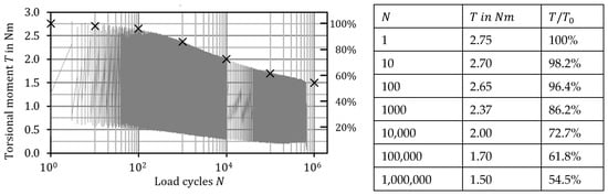
Figure 1.
Moment decay as an indicator of stiffness loss, with the curve approximated by logarithmic and power functions. The reference points (table) serve as additional support.
The initial moment is , at which the maximum fiber-parallel strain (45° to the longitudinal axis on surface) is . The torque remains virtually constant up to approximately 100 cycles. Thereafter, there is a continuous decrease in stiffness over the course of a decade, and only in the last decade until failure does only a slight change occur, up to the point at which the crack is initiated and the failure occurs. The final torque is then approximately , which represents a greater loss of stiffness compared to the shown in [12]. It can be assumed that this caused by the torsional loading and the correspondingly adapted laminate structure. The moment curve was approximated using Equation (1).
4.2. GFRP Volute Springs
The second series of tests was conducted using GFRP volute springs. The springs were manufactured with a large coil spacing to eliminate coil contact. This required the springs to be placed in special spring plates, as shown in Figure 2. During the test, the spring force is continuously recorded as the sum of all four springs. This allows a direct determination of the average force as a function of the number of cycles. This method requires considerably less testing and measurement effort than with individual force measurements, but spring failure can only be directly recorded and assigned to a limited extent. For example, the force curve at length L2 decreases quite steadily, whereas at L3–L5 (longer deflection range, same mean deflection for all springs) a significant drop in force occurs within 100,000 load cycles.
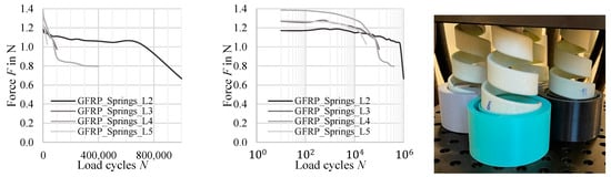
Figure 2.
Test setup for the simultaneous testing of four GFRP volute springs and associated measurement of the total force (4 springs) as a function of load cycles ((Left): linear scale; (middle): log-scale; (right): setup of one test with 4 springs): Lmean equal for all springs; deflection range L2 < L3 < L4 < L5.
Due to the increased load, larger failure zones occur in these springs, which is reflected in the step-like curves with 0.4 N intervals. Caution is advised during the evaluation at this point. Highly stressed areas exist on the inner surface of the spring (), which is lower than in the tapes specimens, shown before [16].
4.3. CFRP Volute Springs
In our own publications, a CFRP volute spring (HT fibers) for use in a mountain bike rear suspension has already been presented [13,14]. The spring force characteristic is progressive, but a linearization is proposed up to approximately 0.6 times of the maximum spring deflection. The shear modulus is used for the material stiffness, which only applies to isotropic materials. For FRP, a suitable substitution parameter must be used. A simple variant would be , but a combination of and would also be possible. The parameters must be determined laminate-dependently using CLT. In this case, too, the linear dependence of the spring force or spring rate on the characteristic value becomes clear.
One spring was cyclically tested at (, , room temperature). This amplitude corresponds to the maximum possible spring deflection. Such a load is not to be expected in real bicycle use, so the fatigue life is underestimated by this test and thus corresponds to a conservative approach. A preliminary FEA simulation (Ansys Workbench ACP) resulted in a maximum fiber-parallel strain of , which represents a challenging range for fatigue considerations due to the relatively high load factor. According to the literature [10] (p. 227), the expected fatigue life of a similar CFRP laminate is approximately at .
The curve was recorded before the test and for , , and load cycles (Figure 3). The usable spring deflection decreases with continued load cycles, meaning that the initial length shortens. Furthermore, the spring rate decreases, from to .
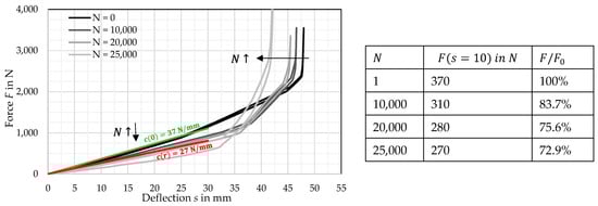
Figure 3.
Spring rate decrease as an indicator for stiffness loss in a CFRP volute spring.
4.4. Comparison of the Stiffness Characteristics of the Different Springs
Based on analytical modeling, the properties of all three samples presented are directly dependent on the material stiffness under torsional loading. Although the tapes differ geometrically, the respective laminate structure is identical with regard to fiber orientation. Therefore, a comparison of the standardized stiffness curves for the moment (GFRP tape) and the forces (GFRP/CFRP springs) is possible and is generally plotted here as stiffness in Figure 4.
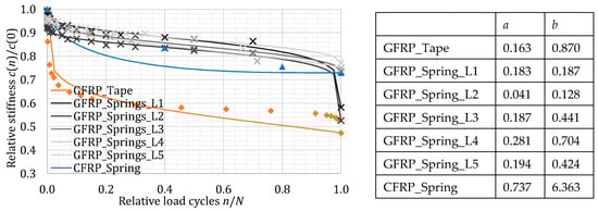
Figure 4.
Comparison of the tested variants in a standardized representation. The stiffness curve of the GFRP springs is almost identical. A similar decrease in stiffness is observed for the CFRP spring. For the GFRP tape, the curve is significantly steeper in phase 1, but from phase 2 onwards, it is similar to the GFRP springs, caused by higher stress and thus damage to the band at the beginning.
The measured values are plotted as data points. The curves approximated using Equation (1) are shown by the colored lines. Parameters and are compared in the corresponding table. The curves for the GFRP springs (grayscale) are almost identical. A similar decrease in stiffness is observed for the CFRP spring (blue); the qualitatively different curve is due to the small number of data points. For the GFRP tape (orange), the curve is significantly steeper in phase 1, but from phase 2 onwards, it is similar to the GFRP springs. The stress is significantly higher than the spring’s stress and thus explains the earlier damage to the band at the start of the test. The CFRP spring is also highly stressed (CFRP has a lower elongation at break than GFRP). According to literature, for lower stresses, CFRP springs would be expected to lie above the lines of the GFRP springs.
5. Summary and Conclusions
Considering load- and stress-dependent material properties in FRP and linking them to equally dependent spring design requirements offers new approaches to the calculation of springs, particularly those subjected to torsion. This required not only making assumptions about the material properties but also defining the spring function requirements as a function of time, load magnitude, and number of load cycles. This linking of requirements and material behavior introduces a fundamentally new aspect that offers a design area for FRP springs. This article, using existing test results, has demonstrated the range of stiffness curves as a function of load magnitude and number of load cycles. The next step for follow-up work would require systematic investigations on other FRP strips, but especially on CFRP strips, to provide statistical evidence for the findings. The findings on volute springs should also be confirmed with further tests. Compared to the design and use of metal springs, this also opens up new possibilities for adapting spring properties depending on the service life. The approach offers points for further investigations.
Author Contributions
Conceptualization, methodology, writing—original draft, visualization: M.P.; validation, supervision: U.K. All authors have read and agreed to the published version of the manuscript.
Funding
This research received no external funding.
Institutional Review Board Statement
Not applicable.
Informed Consent Statement
Not applicable.
Data Availability Statement
All necessary data is given in the paper or published in references.
Conflicts of Interest
The authors declare no conflicts of interest.
References
- Hufenbach, W.; Werner, J.; Körner, I.; Köhler, C. Neuartige Leichtbaufedern in Faserverbundbauweise: Bauweisen/Auslegung/Fertigung. In Ilmenauer Federntag 2010; STZ Spring Technology, TU Ilmenau, Ed.; Seite 31-44; ISLE: Ilmenau, Germany, 2010; ISBN 978-3-938843-57-4. [Google Scholar]
- Scharr, G. Federn aus Faser-Kunststoff-Verbund. In KT 2016; Traditio et Innovatio—Entwicklung und Konstruktion. 14. Gemeinsames Kolloquium Konstruktionstechnik, Rostock, 06.-07.10.2016; Brökel, K., Rieg, F., Stelzer, R.H., Feldhusen, J., Grote, K.-H., Köhler, P., Müller, N., Scharr, G., Eds.; Shaker: Aachen, Germany, 2016; pp. 146–154. [Google Scholar]
- Nowadnick, K. Composite-Blattfeder schlägt Stahlfeder. Available online: https://industrieanzeiger.industrie.de/top-news/composite-blattfeder-schlaegt-stahlfeder/#slider-intro-2 (accessed on 23 August 2022).
- Mubea U-Mobility. XBoard Technologie. Available online: https://xboard.mubea-umobility.com/xboard/technologie (accessed on 20 April 2024).
- Schürmann, H. Konstruieren mit Faser-Kunststoff-Verbunden, 2nd ed.; Springer: Berlin, Germany, 2007; ISBN 978-3-540-72189-5. [Google Scholar]
- Knappe, W.; Schneider, W. Bruchkriterien für unidirektionalen Glasfaser/Kunststoff unter ebener Kurzzeit- und Langzeitbeanspruchung. Kunststoffe 1972, 62, 864–868. [Google Scholar]
- Puck, A. Festigkeitsanalyse von Faser-Matrix-Laminaten: Modelle für die Praxis; Carl Hanser: Munich, Germany, 1996; ISBN 3-446-18194-6. [Google Scholar]
- Knops, M. Analysis of Failure in Fiber Polymer Laminates: The Theory of Alfred Puck; Springer: Berlin/Heidelberg, Germany, 2008; ISBN 9783540757658. [Google Scholar]
- Verein Deutscher Ingenieure e.V. Entwicklung von Bauteilen aus Faser-Kunststoff-Verbund: Berechnungen; Verein Deutscher Ingenieure e.V.: Berlin, Germany, 2006; 2014-3. [Google Scholar]
- Ehrenstein, G.W. Faserverbund-Kunststoffe: Werkstoffe—Verarbeitung—Eigenschaften, 2. völlig überarbeitete Auflage; Carl Hanser Verlag: München, Germany, 2006; ISBN 9783446457546. [Google Scholar]
- Petrich, M.; Titze, S.; Weimann, T.-L.; Kletzin, U. Examinations on composite strips for springs under torsional load. In Proceedings of the 1st Compendium of Modern Spring Technologies 2021, International Conference on Spring Technologies, Canceled, 17 November 2021; Verband der Deutschen Federnindustrie e.V.: Hagen, Germany, 2021; pp. 53–60, ISBN 978-3-00-069928-3. [Google Scholar]
- Feng, Z.; Ma, Q.; Ma, H.; An, Z.; Bai, Z. A Common Model for Stiffness Degradation of Composites at Material and Product Levels. J. Fail. Anal. Prev. 2023, 23, 1550–1557. [Google Scholar] [CrossRef]
- Petrich, M.; Kletzin, U. Design Methodology for Fiber Reinforced Polymer Composite Springs and Experimental Study on a Volute Spring. Compos. Adv. Mater. 2024, 33, 26349833241245134. [Google Scholar] [CrossRef]
- Petrich, M. Entwicklung einer Auslegungsmethode für Federn aus faserverstärkten Kunststoffen und Anwendung am Beispiel der Evolutfeder. Ph.D. Dissertation, TU Ilmenau, Ilmenau, Germany, 2024. [Google Scholar]
- DIN EN ISO 527-5; Plastics—Determination of Tensile Properties—Part 5: Test Conditions for Unidirectional Fibre-Reinforced Plastic Composites (ISO 527-5:2021). German version EN ISO 527-5:2021; DIN Media: Berlin, Germany, 2021.
- Sauer, A.; Thein, L.; Ziems, O. Untersuchungen zum Ermüdungsverhalten von Kegeldruckfedern; Projektseminararbeit; TU Ilmenau: Ilmenau, Germany, 2022. [Google Scholar]


Disclaimer/Publisher’s Note: The statements, opinions and data contained in all publications are solely those of the individual author(s) and contributor(s) and not of MDPI and/or the editor(s). MDPI and/or the editor(s) disclaim responsibility for any injury to people or property resulting from any ideas, methods, instructions or products referred to in the content. |
© 2025 by the authors. Licensee MDPI, Basel, Switzerland. This article is an open access article distributed under the terms and conditions of the Creative Commons Attribution (CC BY) license (https://creativecommons.org/licenses/by/4.0/).