Abstract
This study presents the development and implementation of an electronically actuated steering system in a Formula Student Driverless race car, aiming to support autonomous driving capability. A DC motor with a belt-drive mechanism was integrated into the original steering rack assembly without altering its core mechanical characteristics. The research also includes a validation of the steering geometry using both physical measurements and CAD simulations. The objective of this measurement is to determine the steering angle as a function of the steering wheel input angle, ensuring that the resulting data accurately informs vehicle dynamics models such as the kinematic bicycle model. These steps form the basis for closed-loop control integration in the autonomous driving platform.
1. Introduction
The growing demand for autonomous technologies has prompted universities and industry partners to explore reliable, real-world implementations of vehicle automation. Among these efforts, university-level competitions such as Formula Student Driverless (FSD) offer an applied environment for developing and testing autonomous control systems in race vehicles. In this competition, university teams must convert their conventionally driven race car into a fully autonomous vehicle capable of completing a dynamic driving task without human intervention. This conversion process demands the seamless integration of various hardware and software systems [1].
This paper focuses on one of the key subsystems required for autonomous path tracking, the steering system. To enable precise control, the steering must be actuated electronically for autonomous operation. This usually involves the modification of the existing mechanical system with motors, sensors and controllers to enable closed-loop steering control without manual input. These modifications must maintain or enhance the mechanical reliability of the original system and ensure compatibility with dynamic control algorithms [2].
2. Hardware Solutions in Autonomous Vehicle Platforms
Autonomous vehicle hardware varies greatly depending on the use case. Some platforms focus on low-cost, compact designs for experimentation, while others are built for specific environments that require high precision, power, or safety. The steering layout, type of actuation, and how sensor input is interpreted all directly affect system performance and design constraints.
A project investigated the control of a compact ground vehicle using a skid-steering configuration. The robot was designed without any mechanical steering linkage, instead achieving directional control through differential torque applied to its wheels. This setup reduced mechanical complexity and cost but introduced challenges in lateral motion accuracy, particularly on uneven or slippery terrain. To address these effects, a control scheme was implemented that incorporated a neural network-based prediction layer [3].
An experimental platform focused on the development of a lightweight electric vehicle equipped with autonomous motion capabilities. A single-board computer served as the central controller, interfacing with rotary encoders, LIDAR, and a gear-driven steering motor. The system was designed for simplicity and low cost, making it well-suited for laboratory experiments or short-range indoor navigation. While effective in structured surroundings, the system relied heavily on software tuning and lacked the robustness required for unstructured outdoor use or high-speed control [4].
An agricultural project focused on autonomous steering using a dual-axle control approach. Both front and rear wheels were actuated, enabling precise maneuverability in confined or irregular fields. The system integrated electric and hydraulic components to ensure sufficient actuation force under varying loads and soil conditions. Different steering modes were tested, including a hybrid mode where the front and rear axles steer in coordinated ratios. This allowed turning radius below 3 m in orchard test beds, while minimizing soil disturbance [5].
A commercially oriented research platform was developed to support autonomous driving with a focus on safety and redundancy. The system used a dual-steering setup. This allowed the vehicle to maintain control even if one unit failed or became unresponsive. The system was integrated with modular drive-by-wire units, fault-tolerant controllers, and performance monitoring tools. While offering a high degree of reliability, the integration effort, cost, and development time present a barrier for smaller teams or research groups [6].
3. Steering System Modification of the Test Vehicle
To enable autonomous operation in the Formula Student test vehicle, the original steering system requires modification. The primary objective of the redesign is to implement electronic actuation without compromising the mechanical integrity or reliability of the existing system. However, the design must also be compliant with the current FSD regulations [7,8].
3.1. Original Steering System Overview
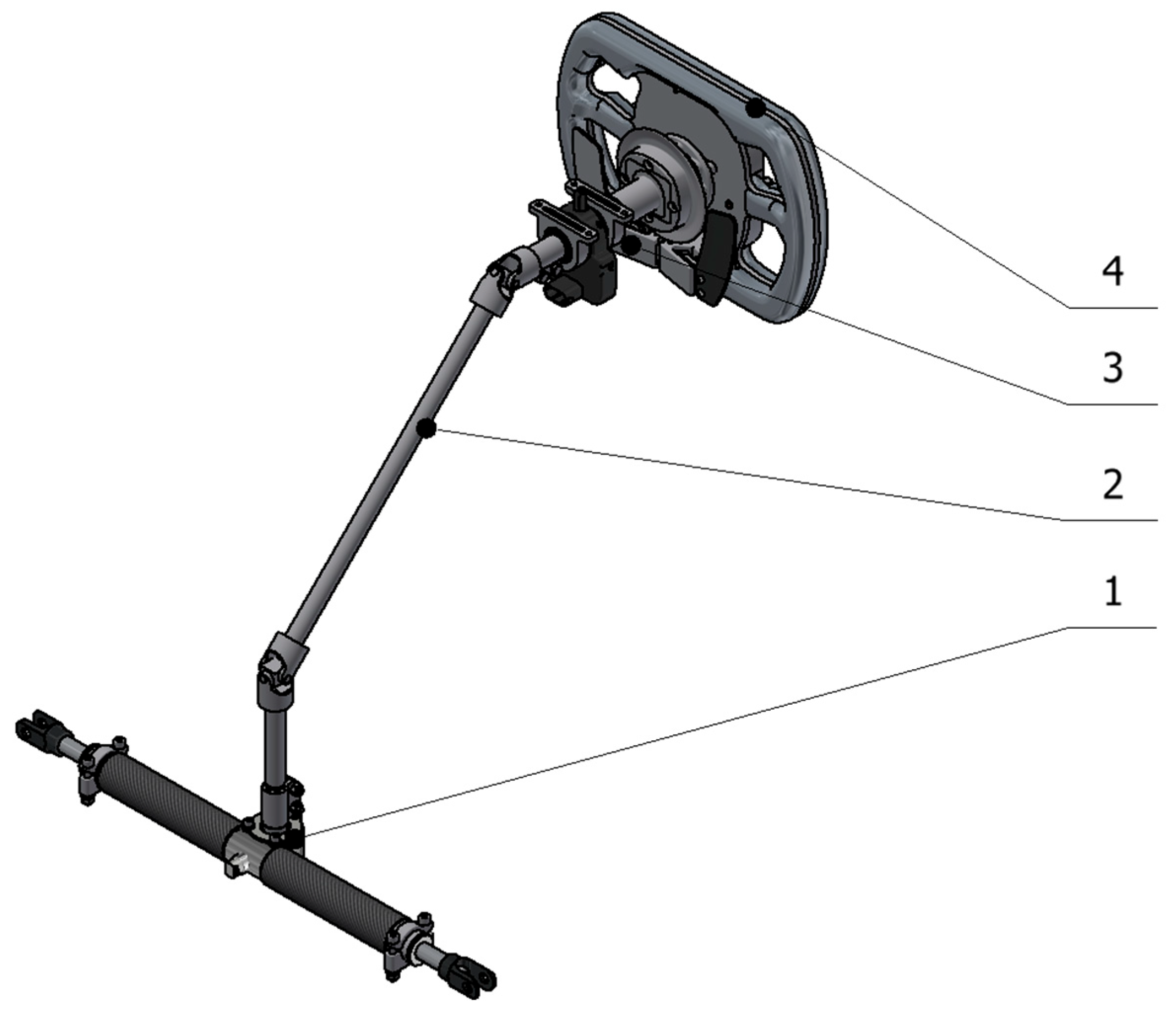
The original system was designed for manual operation, incorporating a lightweight design consisting of aluminum and carbon-fiber materials, with the rack and pinion components manufactured from steel to withstand operational loads. Key parameters of the original steering rack configuration are included in Table 1. In Figure 1, the layout of the system is presented. A custom steering wheel (“4” in Figure 1) is connected to the steering column (“2” in Figure 1) with a quick-release system. A steering angle sensor (“3” in Figure 1) is mounted on the steering column to measure angular position, providing feedback for manual operation and the autonomous control system. The steering column is connected with a splined shaft to the steering rack, which is connected to the wheels by tie rods.

Table 1.
Parameters of the original steering rack.
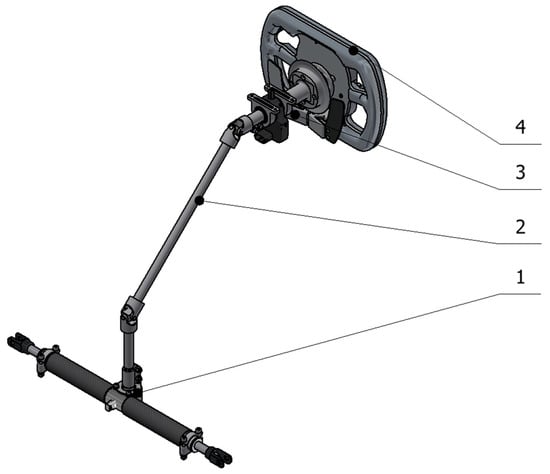
Figure 1.
The original layout of the steering system; 1—steering rack, 2—steering column, 3—steering angle sensor, 4—steering wheel.
3.2. Actuation System Implementation
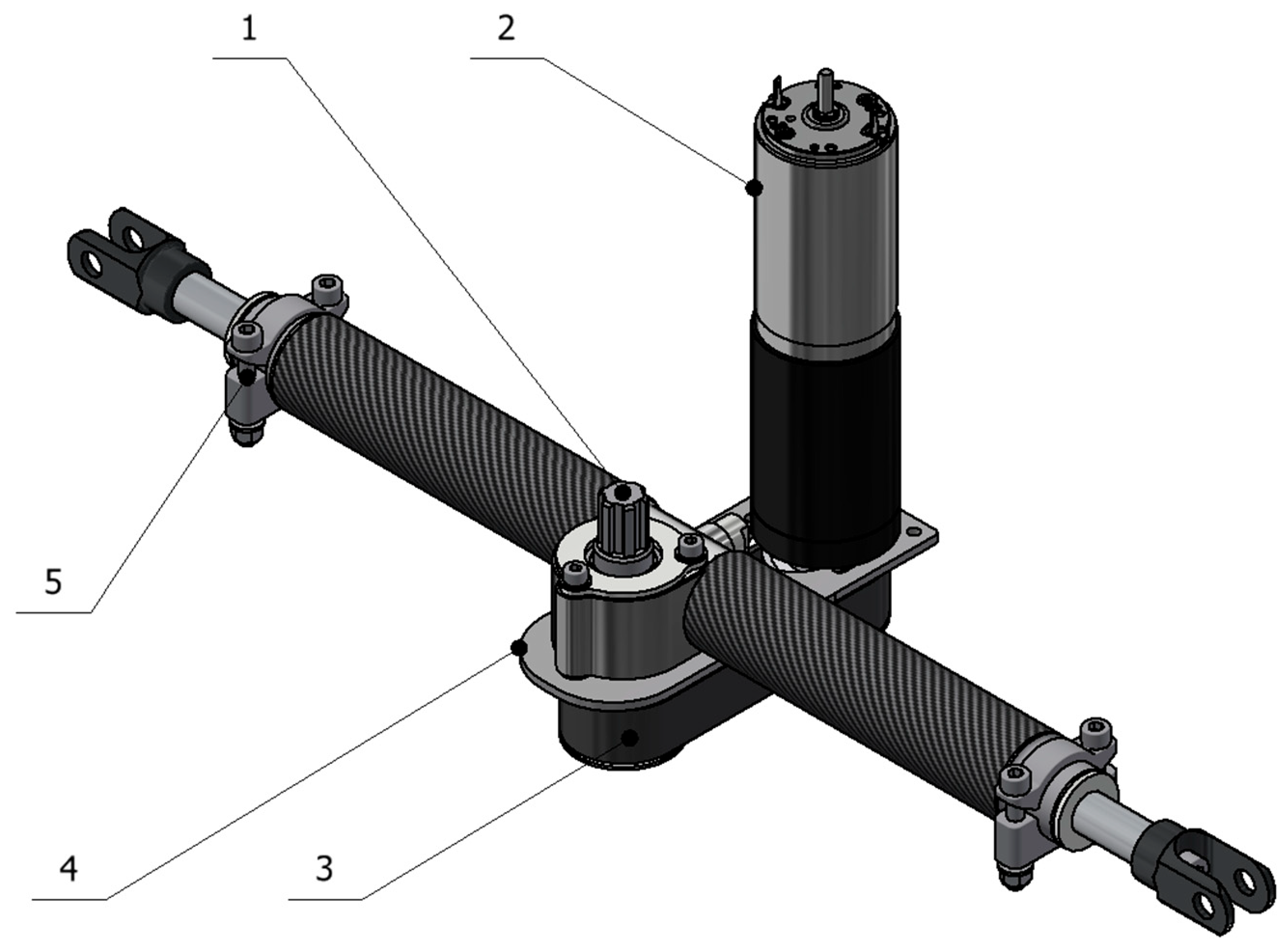
The automated actuation system was developed around a Maxon RE40 DC motor (“2” in Figure 2), selected for its high-power density and compatibility with precision control. The motor was assembled with a GP4C planetary gearhead, offering a gear reduction ratio of 74:1, resulting in a maximum output torque of 22.5 Nm, with a nominal torque of 13 Nm. This configuration exceeds the required steering torque of 16.2 Nm, which was the biggest measured torque on the steering column standstill in a high-grip tarmac environment. 22.5 Nm output ensures reliable operation under full load conditions [9].
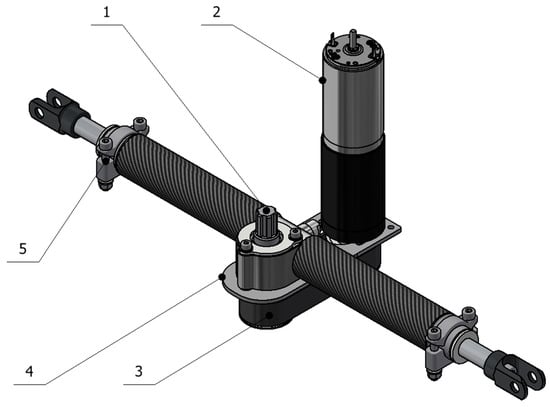
Figure 2.
Modified steering rack: 1—steering rack, 2—Maxon RE40 DC motor assembly, 3—belt drive system, 4—mounting plate, 5—steering rack mounting.
The motor is connected to the steering rack via a belt-drive system (“3” in Figure 2) using a 3M-profile belt with a 1:1 pulley ratio. The input shaft of the rack was redesigned to connect the drive pulley.
Control of the motor is achieved using a Maxon EPOS 4 controller, which interfaces with the vehicle’s high-level control system through a CAN-bus protocol. The controller supports a continuous current draw up to 15 A, while the motor with the gearhead produces the necessary torque output of 16.2 Nm at 7.25 A.
These modifications resulted in a fully integrated, electronically actuated steering system capable of supporting autonomous commands, with the precision and feedback necessary for closed-loop control. The mechanical alterations were carefully designed to maintain compatibility with the original design constraints and ensure seamless integration into the autonomous control framework.
4. The Role of Steering Geometry in Autonomous Vehicle Control
In the context of autonomous driving, the precision of low-level vehicle dynamics modeling has a direct impact on the performance of high-level control systems. Among the key parameters influencing lateral vehicle behavior is the front wheel steered angle, which must be accurately known and interpreted by the controller.
4.1. Relevance of Steering Geometry in Model-Based Control
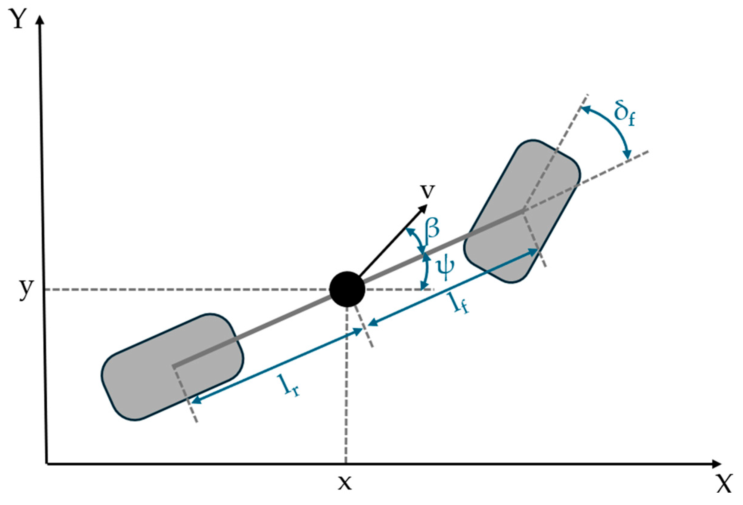
For model-based autonomous vehicle control, precise characterization of the steering geometry is essential, particularly when implementing lateral path tracking. A common approach involves using the kinematic bicycle model, which approximates the vehicle with a simplified two-wheel representation aligned along its longitudinal axis (Figure 3). Despite its conceptual simplicity, the model captures the core geometric dependencies between steering angle, velocity, and turning radius, making it especially useful for low-speed maneuvering and controller design.
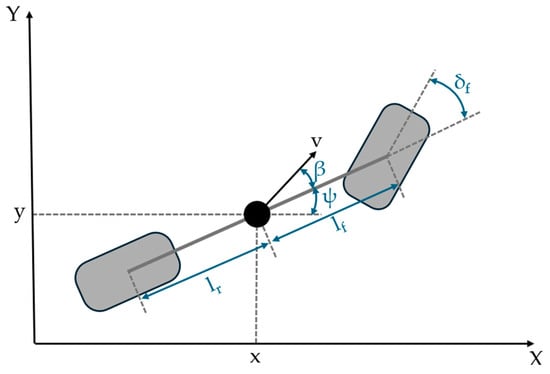
Figure 3.
Kinematic bicycle model.
The model is described by the following equations
In the kinematic bicycle model, and mark the global coordinates of the vehicle’s center of mass, while and represent the velocity components expressed in the vehicle’s local coordinate system. The yaw angle () describes the vehicle’s orientation with respect to the global reference frame and the yaw rate () indicates the rate of change in that orientation. The slip angle () is defined as the angle between the longitudinal axis of the vehicle and the direction of its actual velocity vector. The parameters and represent the distances from the center of mass to the front and rear axles, respectively. The steered angle at the front wheel serves as one of the primary controls input and directly determines the curvature of the vehicle’s path in the model [10,11].
The third and fourth equations illustrate that the vehicle’s yaw rate () is directly affected by the front steered angle (), meaning even minor discrepancies can cause trajectory errors. Ensuring an accurate mapping between measurable steering wheel input and steered angle () is therefore essential for reliable autonomous operation. Without this, the control system would operate on incorrect assumptions, leading to degraded performance or instability, particularly during dynamic maneuvers such as lane changes or tight cornering.
4.2. Measurement and Validation of Steering Geometry
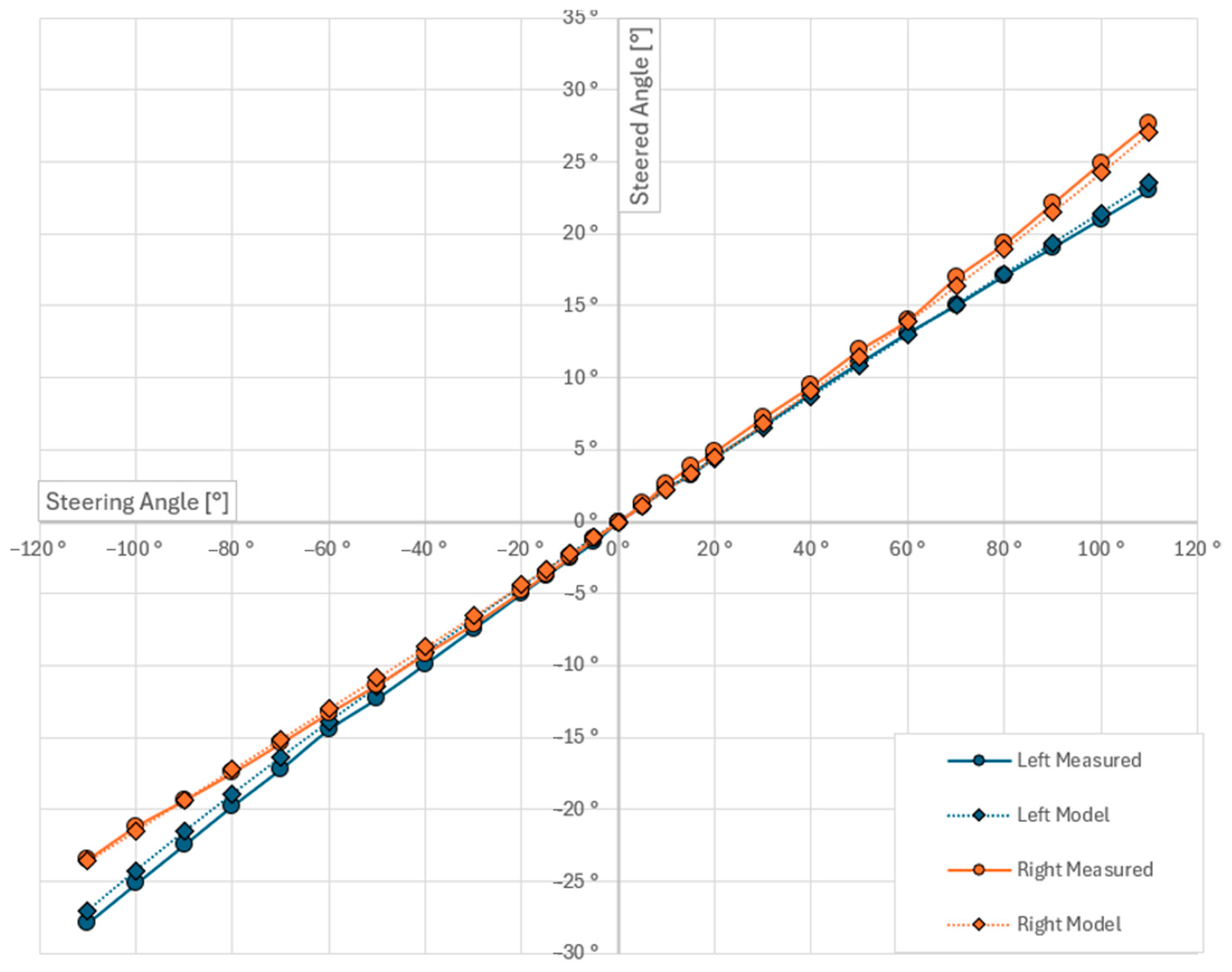
To quantify the steering geometry and ensure consistency with the control model, a set of measurements was performed on the test vehicle. The goal was to establish the relationship between the steering wheel angle and the actual steered angle of both front wheels. This empirical data was then compared with the theoretical values obtained from the vehicle’s CAD model, allowing for validation of the manufactured steering assembly. The measurement was conducted by incrementally rotating the steering wheel across its full range of motion and recording the corresponding wheel angles using laser projection techniques combined with trigonometric calculations. Both left and right front wheel angles were measured, enabling the identification of any mechanical asymmetries or alignment deviations. To verify the accuracy of the physical build, the same measurement procedure was replicated in the CAD environment using the vehicle’s digital steering kinematics. The results (Figure 4) show high correlation, with only minor differences observed. Most likely due to manufacturing tolerances, sensor mounting and measurement inaccuracies. These deviations were within acceptable margins and confirmed that the manufactured geometry matched the design intent.
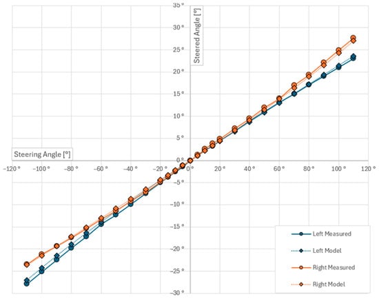
Figure 4.
Comparison of modeled and measured steering geometry.
Figure 4 presents the measured front wheel angles as a function of the steering wheel angle. The curves indicate symmetric behavior and a consistent, mostly linear relationship within the central region, with slight nonlinearity appearing near the steering limits.
This validated mapping will serve as a reference for integrating real-time steering measurements into the autonomous control algorithms, ensuring that the input in the kinematic model reflects the actual vehicle response.
5. Summary and Achieved Results
This paper presented the development and integration of an electronically actuated steering system in a Formula Student Driverless (FSD) test vehicle. The original rack-and-pinion steering mechanism was retained in structure but augmented with a Maxon RE40 DC motor, a GP4C planetary gearhead, and a belt-drive interface to allow autonomous control without compromising mechanical integrity. The actuation system was designed to deliver sufficient torque to meet the highest loads encountered during static cornering on high-grip tarmac.
To support accurate vehicle modeling, the research also focused on quantifying and validating the steering geometry. A measurement setup was implemented to record both front wheel angles as a function of the steering wheel input using laser projection and trigonometric post-processing. The results showed strong agreement with the vehicle’s digital CAD model, confirming the accuracy of the fabricated system and identifying only minor deviations likely due to sensor placement or manufacturing tolerances. In addition, the study highlighted the critical role of steering angle estimation in path-tracking algorithms based on the kinematic bicycle model.
The developments mark a solid advancement toward deploying an operational autonomous platform within the Formula Student framework, setting the stage for the refinement of control strategies and on-track validation.
Author Contributions
Conceptualization, methodology, validation, formal analysis, and visualization, L.I.O. and M.K.; writing—draft preparation, L.I.O.; supervision, project administration, Z.P. All authors have read and agreed to the published version of the manuscript.
Funding
The publication was created in the framework of the Széchenyi István University’s VHFO/416/2023-EM_SZERZ project entitled “Preparation of digital and self-driving environmental infrastructure developments and related research to reduce carbon emissions and environmental impact” (Green Traffic Cloud).
Institutional Review Board Statement
Not applicable.
Informed Consent Statement
Not applicable.
Data Availability Statement
Data for this study is not publicly available.
Acknowledgments
The authors would like to express their sincere gratitude to the Arrabona Racing Team for providing access to the Formula Student vehicle used in this study. Special thanks are also due to the Vehicle Research Centre of Széchenyi István University for granting access to prior experimental data, which supported the evaluation process.
Conflicts of Interest
The authors declare no conflicts of interest.
References
- Kabzan, J.; de la Iglesia Valls, M.; Reijgwart, V.; Hendrikx, H.F.C.; Ehmke, C.; Prajapat, M.; Bühler, A.; Gosala, N.; Gupta, M.; Sivanesan, R.; et al. AMZ Driverless: The full autonomous racing system. J. Field Robot. 2020, 37, 1267–1294. [Google Scholar] [CrossRef]
- Manca, R.; Circosta, S.; Khan, I.; Feraco, S.; Luciani, S.; Amati, N.; Bonfitto, A.; Galluzzi, R. Performance assessment of an electric power steering system for driverless Formula Student vehicles. Actuators 2021, 10, 165. [Google Scholar] [CrossRef]
- Slawiñski, E.; Rossomando, F.; Chicaiza, F.A.; Moreno-Valenzuela, J.; Mut, V. LSTM network in bilateral teleoperation of a skid-steering robot. Neurocomputing 2024, 602, 128248. [Google Scholar] [CrossRef]
- Shaik, Z.B.; Peddakrishna, S. Design and implementation of electric vehicle with autonomous motion and steering control system using single board computer and sensors. Results Eng. 2025, 25, 103995. [Google Scholar] [CrossRef]
- Bayano-Tejero, S.; Sarri, D.; Sola-Guirado, R.R. Design and field validation of a dual-axle steering system for autonomous tractors. Comput. Electron. Agric. 2025, 231, 110000. [Google Scholar] [CrossRef]
- He, S.; Xu, X.; Xie, J.; Wang, F.; Liu, Z. Adaptive control of dual-motor autonomous steering system for intelligent vehicles via Bi-LSTM and fuzzy methods. Control Eng. Pract. 2023, 130, 105362. [Google Scholar] [CrossRef]
- Brokelind, H.; Burgman, O.; Calsson, D.; Eklund, E.; Forsman, O.; Miltén, P. Hardware Development on an Autonomous Formula Car: A Chalmers Formula Student Driverless Project Report; Chalmers University of Technology: Göteborg, Sweden, 2019. [Google Scholar]
- Formula Student Germany. Formula Student Rules 2025. Available online: https://www.formulastudent.de/rules/ (accessed on 12 June 2025).
- Cao, D.; Tang, B.; Jiang, H.; Yin, C.; Zhang, D.; Huang, Y. Study on low-speed steering resistance torque of vehicles considering friction between tire and pavement. Appl. Sci. 2019, 9, 1015. [Google Scholar] [CrossRef]
- Baslamisli, S.C.; Polat, I.; Kose, I.E. Gain scheduled active steering control based on a parametric bicycle model. In Proceedings of the 2007 IEEE Intelligent Vehicles Symposium, Istanbul, Turkey, 13–15 June 2007; pp. 1168–1173. [Google Scholar] [CrossRef]
- Kong, J.; Pfeiffer, M.; Schildbach, G.; Borrelli, F. Kinematic and dynamic vehicle models for autonomous driving control design. In Proceedings of the 2015 IEEE Intelligent Vehicles Symposium (IV), Seoul, Republic of Korea, 28 June–1 July 2015; pp. 1094–1099. [Google Scholar] [CrossRef]
Disclaimer/Publisher’s Note: The statements, opinions and data contained in all publications are solely those of the individual author(s) and contributor(s) and not of MDPI and/or the editor(s). MDPI and/or the editor(s) disclaim responsibility for any injury to people or property resulting from any ideas, methods, instructions or products referred to in the content. |
© 2025 by the authors. Licensee MDPI, Basel, Switzerland. This article is an open access article distributed under the terms and conditions of the Creative Commons Attribution (CC BY) license (https://creativecommons.org/licenses/by/4.0/).

