Proceeding Paper

Investigation of Triple-Microcantilever Sensor for Ultra-Low Mass-Sensing Applications †

1
Department of Theory of Mechanisms and Machines, Faculty of Industrial Technology, Technical University of Sofia, 1797 Sofia, Bulgaria
2
AMG Technology Ltd., Microelectronica Industrial Zone, 2140 Botevgrad, Bulgaria
3
Department of Electronics, Faculty of Electronic Engineering and Technologies, Technical University of Sofia, 1797 Sofia, Bulgaria
*
Author to whom correspondence should be addressed.
Presented at the 14th International Scientific Conference TechSys 2025—Engineering, Technology and Systems, Plovdiv, Bulgaria, 15–17 May 2025.
Eng. Proc. 2025, 100(1), 60; https://doi.org/10.3390/engproc2025100060
Published: 17 July 2025

Abstract

This paper discusses a new method and sensor for the detection of ultra-low masses, such as those of viruses and biomarkers. The sensor contains three microcantilevers with a common substrate that vibrates. The detection method processes phase-shifted signals from Wheatstone bridges from connected piezoresistors formed on the vibrating microcantilevers and passive resistors on the rigid substrate. Each microcantilever has a gold pad that can be either active or passive. When a mass is detected, the shape of the amplitude–frequency response changes. The proposed method has high mass sensitivity and can respond up to one minute, which is an important challenge for nanocantilever sensors.

1. Introduction

Microcantilevers with sharp tips have been used in atomic force microscopy for topographic imaging of non-conducting surfaces for over 40 years [1,2]. Single smooth microcantilevers respond to the absorption of molecules and microorganisms by bending and changing their natural frequency [3,4]. Due to their high sensitivity and fast response, they have found wide application in biochemistry, medicine, and physics [5]. The use of two single microcantilevers was intended to improve the sensor performance by introducing a second reference sensor that could be used to measure the natural frequency deviation of the active sensor [6]. Another variation of these sensors is microcantilever arrays, in which the number of cantilevers can vary from 4 to 32 [7]. Microcantilever sensor arrays have diverse applications such as artificial noses [8], analyte detection [9], and DNA hybridization [10].
The authors of this paper have extensive experience in the investigation of dual-microcantilever sensors for the detection of viruses in gas. A common feature in the working principle is that the microcantilevers are attached to a common rigid substrate, which vibrates in a frequency range including the eigenfrequencies of the microcantilevers. The eigenfrequencies of the microcantilevers in the nominal state are shifted by a small value so that the two amplitude–frequency characteristics intersect. When mass is added to the surface of one of the microcantilevers, the intersection of the amplitude–frequency characteristics shifts, and this is an indication of a change in the mass of that beam [11,12,13].
Triple-microcantilever sensors have a more complex design than dual-microcantilever sensors but offer some new capabilities in terms of increased active surface for real-time detection of pathogens, result fidelity, strongly reduced false detection, sensor reliability, and ease of use. The triple-microcantilever coupled sensor system discussed in [14] shows that the mass is comparable to that of a single resonator, and in comparison, to single cantilevers. The system offers significantly improved signal compensation, reduced time for detection of an event, and an opportunity to decode the cantilever where the analyte was captured on the surface, thus providing new options for multi-analyte detection.
The aim of this paper is to investigate the ultra-low mass detection capabilities of a sensor composed of three microcantilevers with a common vibrating rigid substrate. The two offsets of the intercepts in the amplitude–frequency characteristics are the signal of the presence of mass added to a particular microcantilever.

2. Design Concepts and Features of the Investigated Tri-Microcantilever Sensors

The three-cantilever piezoresistor sensors investigated here were designed and fabricated at AMG Technology, Bulgaria, as part of a joint project with a team from the Technical University of Sofia.
During the research, two basic designs of three-cantilever sensors were selected (Figure 1). The first type, shown in Figure 1a, is characterized by containing four active piezoresistors. The second type of sensor (Figure 1b) contains four passive resistors in addition to the four active piezoresistors.
In Figure 1, the common elements can be distinguished, which, in addition to the mentioned piezoresistors and resistors, also contain gold functionalization pads and heaters. The golden pads are formed on each cantilever, allowing each of them to be activated and become sensitive to the detected mass, and the others to serve as a reference. On each of the three cantilevers, there is formed an outer rectangular current frame called a heater. All the heaters are connected in series with intermediate terminals for each cantilever. The heaters have a multifunctional purpose. One of these purposes is to change the frequency of the cantilevers by heating and/or by Lorentz forces [12].
In addition, the terminals of the heater provide the possibility that selected sections of the current loop, located between the respective terminals, can be shunted with a parallel resistance of low value. This is a new functionality specific to these sensors. There are also four rectangular holes in the fixed end of the microcantilevers. These holes are used for additional mechanical tuning of the natural frequency.
An important feature in these sensors is related to the different schemes of connecting the piezoresistors in a bridge. One embodiment of a bridging scheme of a differential connection of two piezoresistors on microcantilevers and two passive resistors in a single bridge, B1, is shown schematically in Figure 2a.
Therein, piezoresistor 4′1 with one resistor 40 having a constant value forms the voltage divider 91, and the piezoresistor and 42 with another resistor 40 having a constant value forms the voltage divider 92. Thus, each of the output signals V11 and V12 of the voltage dividers 91 and 92 depends on the amplitude (A1 or A2) and phase (ϕ1 or ϕ2) of an oscillation of a single microcantilever (31 or 32) and, therefore, has a sinusoidal shape similar to the mechanical oscillation of the cantilever.
Another amplifying version of the connection 5′1 of the same resistors 4i of the bridging scheme is shown schematically in Figure 2b. Specific to this variant of the bridging circuit is that, all conditions and effects being equal, the sinusoidal signal V’11(ϕ1) is inverted (180° out of phase) with respect to the signal V11(ϕ1) from the first variant of the coupling. Similarly, there are two coupling variants of the second bridge 52. For both of these bridge circuit variants, under the same conditions and effects, each of the sinusoidal signals V22(ϕ3) and V’22(ϕ3) is mutually inverted (offset 180° in phase).
The general appearance of this variant of the three-cantilever sensor is shown in Figure 3, with a total of four piezoresistors, one each on the reference cantilevers C1 and C3 and two on the working microcantilever C2. In this case, in addition to the four piezoresistors on the microcantilevers, four passive resistors of constant value are also used, located on the non-deformable substrate.
These totals of eight piezoresistors and passive resistors are connected in two bridges, as was discussed above. Crucially, the two dividers involving the C2 piezoresistors generate identical signals when the oscillation modes of the cantilever are on the bend. This allows independent comparison of the instantaneous values of their signals with the signals from the piezoresistors on the C1 and C3 consoles. Thus, the change in the parameters of the C2 cantilever is registered simultaneously in both bridges “Bridge #1” and “Bridge #2”.
An amplifying embodiment of the wiring diagram in full bridge 51, when only four piezoresistors arranged on three micro-consoles are included in bridge 91, is shown in Figure 4a. Accordingly, the signal V1 from the voltage divider 91 depends on the amplitudes A1 and A2 and the phases ϕ1 and ϕ2 of forced oscillation of the micro-consoles 31 and 32, and the signal V2 from the voltage divider 92 depends on the amplitudes A2 and A3 and the phases ϕ2 and ϕ3 of forced oscillation of the microcantilevers 32 and 33.
A differential wiring diagram of this other variant of sensor 1 in a full 5′1 bridge is shown in Figure 4b. Accordingly, the signal V1 from the voltage divider 91 depends on the amplitudes A1 and A2 and the phases ϕ1 and ϕ2 of the forced oscillation of the micro-consoles 31 and 32, and the signal V’2 from the voltage divider 9′2 depends on the amplitudes A2 and A3 and the phases ϕ2 and ϕ3 of the forced oscillation of the micro-consoles 32 and 33. In contrast to the previous case, the signal V’2 is inverted 180° with respect to the coupling from the bridge 51.
The specific condition is that the resonant frequencies of the microcantilevers change monotonically with their position in the array. In this case, the condition
f1 < f2 < f3
A key feature of sensors of this type is the arrangement of the micro-cantilevers in a row of monotonically increasing resonant frequency, with alternating reference (at odd positions) and active (at even positions).

3. Compilation of an Electromechanical Model of the Triple-Microcantilever Sensor

For the sensor with four piezoresistors, the location of the resistors on the corresponding microcantilevers is shown in Figure 5a. Figure 5b shows the corresponding Wheatstone bridge in which the piezoresistors are connected in agreement with the logic outlined in the previous section.
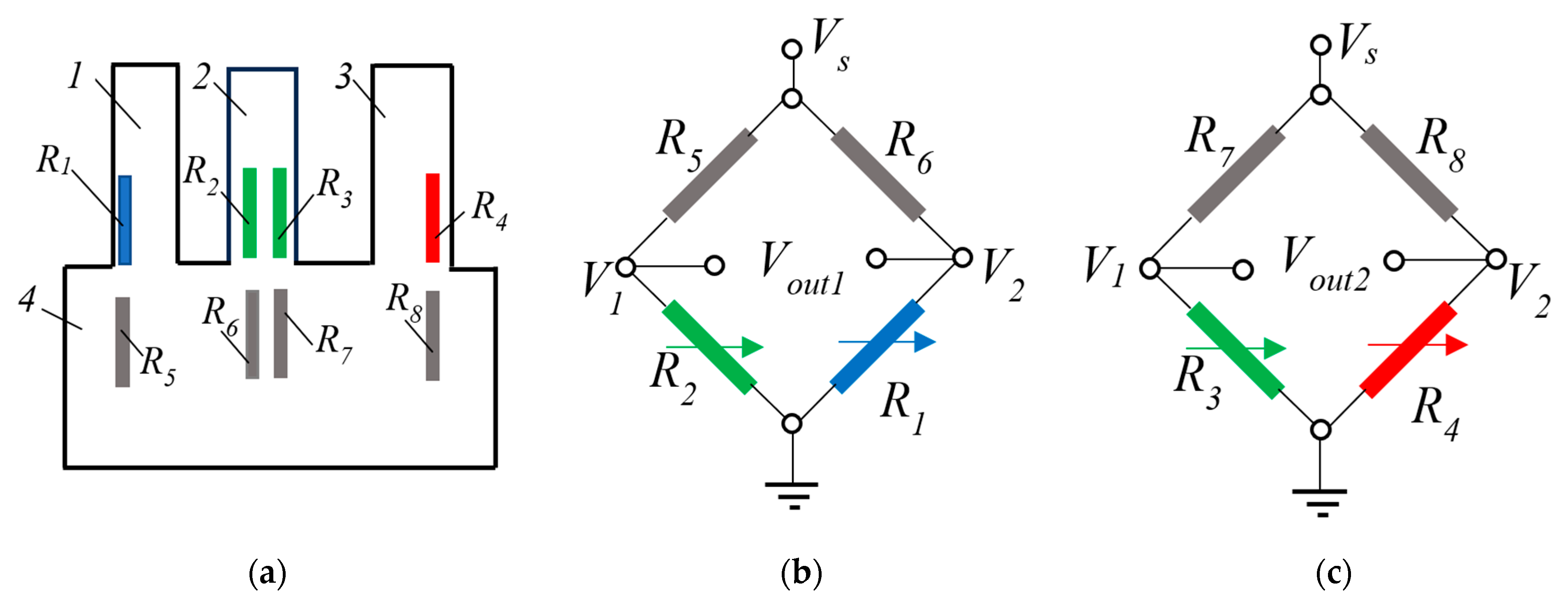
Similarly, for the sensor with four piezoresistors and four resistors, the location of the resistors on the respective microcantilevers and the four resistors on the substrate is shown in Figure 6a. Figure 6b shows the first Wheatstone bridge with the piezoresistors R1 and R2 and the resistors R5 and R6 connected. The second Wheatstone bridge, consisting of the piezoresistors R3 and R4 and the resistors R7 and R8, is shown in Figure 6c.
The output voltage V o u t of the Wheatstone bridge with the four piezoresistors (Figure 5b) can be calculated according to the formula
V o u t = V 1 V 2 = R 2 R 1 + R 2 R 4 R 4 + R 3 V s = R 1 R 4 R 2 R 3 ( R 1 + R 2 ) ( R 4 + R 3 ) V s
where V 1 and V 2 are the voltage of the first and second dividers of the Wheatstone bridge, and V s is the supplying voltage.
Similarly, the output voltage V o u t 1 of the first Wheatstone bridge with four piezoresistors and four resistors (Figure 6b) can be determined by
V o u t 1 = R 2 R 6 R 1 R 5 R 2 + R 5 R 6 + R 1 V s = R 5 R 2 R 1 R 2 + R 5 R 6 + R 1 V s
And the output voltage V o u t 2 of the second Wheatstone bridge (Figure 6c) is
V o u t 2 = R 3 R 8 R 4 R 7 R 3 + R 7 R 8 + R 4 V s = R 7 R 3 R 4 R 3 + R 7 R 8 + R 4 V s
The simplification in (3) is valid if R 5 + R 6 .and in (4) if R 7 + R 8 .
It is assumed that the common substrate of the microcantilevers vibrates by a harmonic function y 1 of the form
y 1 = a s i n ω t
where a is the amplitude of the actuation function, ω   is the circular frequency, and t is the time.
Considering a lumpen dynamical model [13,15] of every cantilever, the vibrations can be expressed by the solution of an ordinary differential equation in the form
y i = B i s i n ω t + ψ i
where y i is the free motion, and the amplitude B i of the forced oscillations of the i-th cantilever is
B i = a ω 2 ω 2 ϖ i 2 2 4 β i 2 ω 2
The phase of the vibrations of the i-th cantilever is
ψ i = arctan 2 ω β i ω 2 ϖ i 2
where ϖ i is the natural (resonant) circular frequency of the i-th cantilever and β i is the damping factor of the i-th cantilever.
As is known [16,17], the resistance of a piezoresistor is given by the relation
R j = R 0 + R j
where the variable part R j of the piezoresistor in the solution (6) can be considered proportional to the displacement of the free end of the cantilever on which it is formed, i.e.,
R j = k r B i sin ω t + ψ i
where k r is the piezoresistivity coefficient.
Using these formulae, a pre-selection of the parameters and the parameters of the microcantilevers was performed.

4. Experimental Results

Prototypes of microcantilevers with a length in the range of 250–350 µm, a width in the range of 80–120 µm, and a thickness in the range of 2.5–6.0 µm were fabricated. These microcantilevers are of relatively “large size” with respect to modern trends of similar sensors where nano-cantilevers are applied [18,19,20,21]. To investigate the amplitude–frequency responses of the triple-microcantilever sensor, a dedicated experimental setup was built, as shown in Figure 7. A peculiarity of the system is that the eigenfrequencies of the microcantilevers are in the range of 60 to 120 kHz. This necessitated the use of a data acquisition system with a sampling rate of 2 MS/s. For this purpose, a National Instruments PXI system was used. A Digilent sine signal generator was used to generate a high-frequency sine signal for a piezoelectric actuator, used to excite mechanical vibrations at the common substrate of the three microcantilevers. A LabVIEW program was used to process the signals [11]. The experimental setup is capable of measuring frequencies up to 300 kHz with a resolution of 0.01 Hz, which was quite sufficient for the requirements of the proposed method.
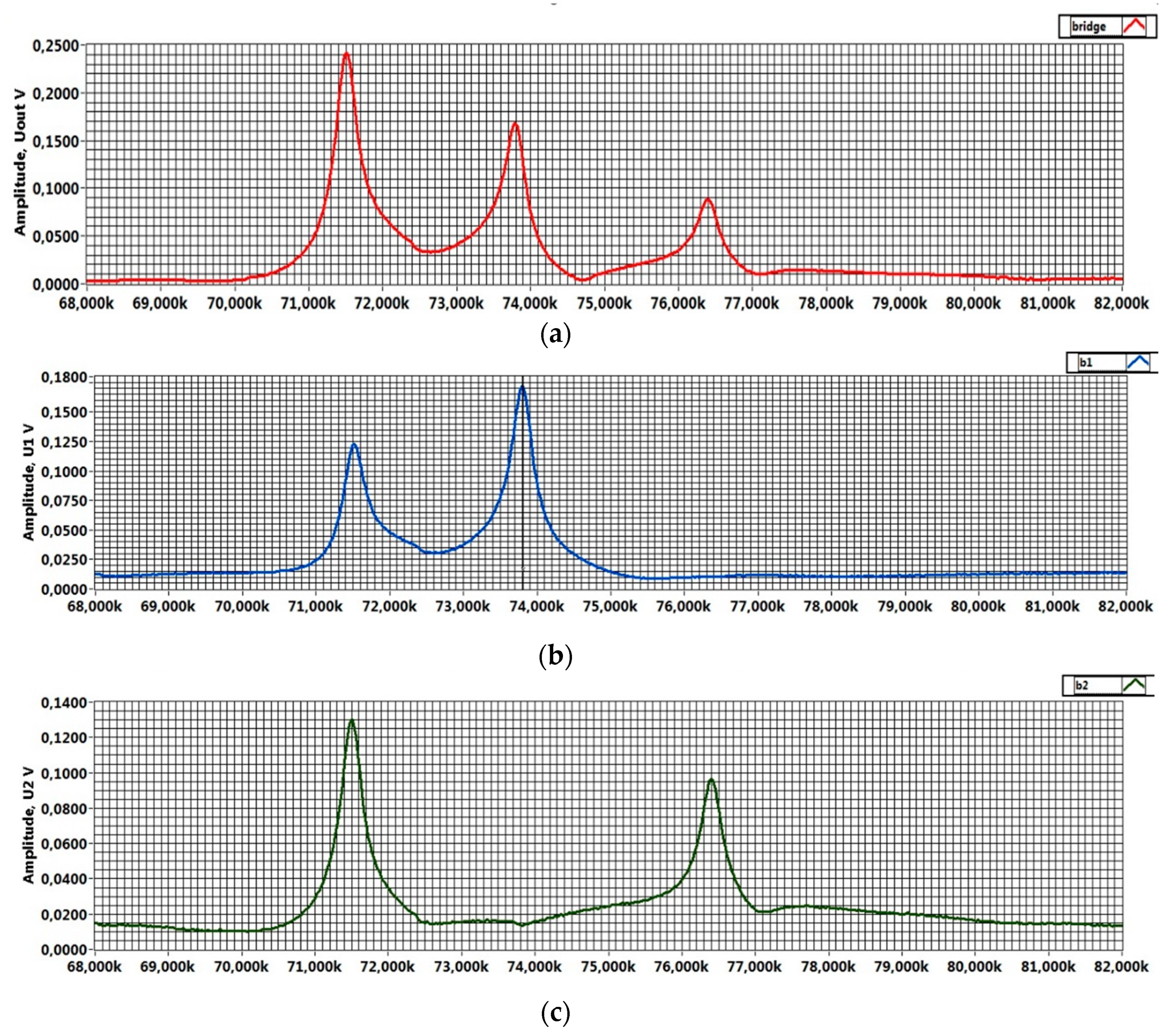
Figure 8 presents initial test results from the triple-cantilever sensor with four piezoresistors and four resistors. In Figure 8a, the result of the full bridge of the three cantilevers is shown. Figure 8b depicts the first and second peaks of the amplitude–frequency response and Figure 8c shows the first and third peaks.

5. Conclusions

A new method and sensor containing three microcantilevers on a common rigid substrate was developed for sensing the availability of ultra-low mass analytes, like viruses, pathogens, bio-markers, and trace gases that are bound on the cantilever surface. To achieve detection selectivity, at least one cantilever is provided with a specifically coated pattern. Respectively, the surface of one or three cantilevers is functionalized to bind the same or different targeted analyte(s). Thus, two approaches—with a single active and two reference cantilevers or with three active ones—are formulated. For each of these approaches, two different full Wheatstone bridge configurations have been prototyped. Accordingly, the sensors were fabricated and tested in two of their varieties.
“Large size” microcantilevers significantly (up to ×104) increased the active area; these devices ensure real-time detection (i.e., time between detected events ≤1 min) of an analyte’s availability in gases.
Analogue electrical signals from piezoresistors with identical parameters located on adjacent cantilevers provide various options for their controllable mixing. Particularly, any two of said analogue signals can be either amplified or compensated, meaning parameter drift can be eliminated.
Capturing an ultra-small mass analyte causes a relative eigenfrequency change in a microcantilever by a factor of Δf/f ≈ 10−6. Despite the ultra-small frequency shift, due to the above-mentioned drift compensation, the new method provides reliable detection of an analyte capturing an event on a specifically functionalized cantilever.
Due to electrically recurrently connected piezoresistors in full bridge configurations, the cantilever that was binding an analyte can be recognized, and initial signal compensation can be recovered, meaning the next event can be detected. Thus, besides the availability of an analyte, its concentration can be assessed, too.

Author Contributions

Conceptualization, V.S., T.T., and L.B.; methodology, V.S. and B.G.; software, B.G.; validation, V.S., N.N., and L.B.; formal analysis, B.G., N.N., and T.T.; investigation, T.T. and L.B.; resources, V.S.; data curation, B.G. and N.N.; writing—original draft preparation, V.S. and T.T.; writing—review and editing, V.S. and N.N.; visualization, L.B.; supervision, B.G.; project administration, T.T.; funding acquisition, T.T. All authors have read and agreed to the published version of the manuscript.

Funding

The results in this research were obtained under project №252ПД0031-05, funded by the subsidy of the Technical University of Sofia. This research was also funded by the European Union-NextGenerationEU through the National Recovery and Resilience Plan of the Republic of Bulgaria, project № BG-RRP-2.004-0005.

Institutional Review Board Statement

Not applicable.

Informed Consent Statement

Not applicable.

Data Availability Statement

The original contributions presented in this study are included in the article. Further inquiries can be directed to the corresponding author(s).

Conflicts of Interest

Author Vladimir Stavrov was employed by the company AMG Technology Ltd. The remaining authors declare that the research was conducted in the absence of any commercial or financial relationships that could be construed as a potential conflict of interest.

References

  1. Koçum, C.; Ülgen, Ş.D.; Çubukçu, E.; Pişkin, E. Atomic Force Microscopy Tips (Cantilevers) as Molecular Nucleic Acid Sensors. Ultramicroscopy 2006, 106, 326–333. [Google Scholar] [CrossRef] [PubMed]
  2. Alunda, B.O.; Lee, Y.J. Review: Cantilever-Based Sensors for High Speed Atomic Force Microscopy. Sensors 2020, 20, 4784. [Google Scholar] [CrossRef] [PubMed]
  3. Ramos, D.; Calleja, M.; Mertens, J.; Zaballos, A.; Tamayo, J. Measurement of the Mass and Rigidity of Adsorbates on a Microcantilever Sensor. Sensors 2007, 7, 1834–1845. [Google Scholar] [CrossRef] [PubMed]
  4. Jin, D.; Li, X.; Liu, J.; Zuo, G.; Wang, Y.; Liu, M.; Yu, H. High-Mode Resonant Piezoresistive Cantilever Sensors for Tens-Femtogram Resoluble Mass Sensing in Air. J. Micromech. Microeng. 2006, 16, 1017–1023. [Google Scholar] [CrossRef]
  5. Lang, H.P.; Gerber, C. Microcantilever Sensors. In Topics in Current Chemistry; Samori, P., Ed.; Springer: Berlin/Heidelberg, Germany, 2008; Volume 285, pp. 1–27. [Google Scholar]
  6. Tang, L.; Xu, P.; Li, M.; Yu, H.; Li, X. Integrated Resonant Dual-Microcantilevers Combined Sensor with Accurate Identification and Highly-Sensitive Detection to H2S Gas. In Proceedings of the 2019 20th International Conference on Solid-State Sensors, Actuators and Microsystems & Eurosensors XXXIII (TRANSDUCERS & EUROSENSORS XXXIII), Berlin, Germany, 23–27 June 2019; pp. 338–341. [Google Scholar]
  7. Boisen, A.; Thundat, T. Design & Fabrication of Cantilever Array Biosensors. Mater. Today 2009, 12, 32–38. [Google Scholar] [CrossRef]
  8. Baller, M.K.; Lang, H.P.; Fritz, J.; Gerber, C.; Gimzewski, J.K.; Drechsler, U.; Rothuizen, H.; Despont, M.; Vettiger, P.; Battiston, F.M.; et al. A Cantilever Array-Based Artificial Nose. Ultramicroscopy 2000, 82, 1–9. [Google Scholar] [CrossRef] [PubMed]
  9. Alodhayb, A.; Rahman, S.M.S.; Rahman, S.; Georghiou, P.E.; Beaulieu, L.Y. A 16-Microcantilever Array Sensing System for the Rapid and Simultaneous Detection of Analyte. Sens. Actuators B Chem. 2016, 237, 459–469. [Google Scholar] [CrossRef]
  10. Tian, F.; Hansen, K.M.; Ferrell, T.L.; Thundat, T.; Hansen, D.C. Dynamic Microcantilever Sensors for Discerning Biomolecular Interactions. Anal. Chem. 2005, 77, 1601–1606. [Google Scholar] [CrossRef] [PubMed]
  11. Banchelli, L.F.; Ganev, B.T.; Todorov, T.S. Sustainability Validation of a LabVIEW Based System for Biomarkers Detection. In Proceedings of the 2023 XXXII International Scientific Conference Electronics (ET), Sozopol, Bulgaria, 13–15 September 13 2023; pp. 1–6. [Google Scholar]
  12. Banchelli, L.; Todorov, G.; Stavrov, V.; Ganev, B.; Todorov, T. Evaluation of the Influence of Lorentz Forces on the Natural Frequencies of a Dual-Microcantilever Sensor for Ultralow Mass Detection. Micro 2024, 4, 572–584. [Google Scholar] [CrossRef]
  13. Banchelli, L.; Todorov, G.; Stavrov, V.; Ganev, B.; Todorov, T. Investigating a Detection Method for Viruses and Pathogens Using a Dual-Microcantilever Sensor. Micromachines 2024, 15, 1117. [Google Scholar] [CrossRef] [PubMed]
  14. Pakdast, H.; Lazzarino, M. Triple Coupled Cantilever Systems for Mass Detection and Localization. Sens. Actuators A Phys. 2012, 175, 127–131. [Google Scholar] [CrossRef]
  15. NT-MDT Spectrum Instruments. Theoretical Background of SPM, 2.1.2 Deflections Under the Vertical (Normal) Force Component. Available online: https://www.ntmdt-si.com/resources/spm-theory/theoretical-background-of-spm/2-scanning-force-microscopy-(sfm)/21-cantilever/212-deflections-under-the-vertical-normal-force-component (accessed on 3 April 2025).
  16. Allen, J.J. Micro Electro Mechanical System Design, 1st ed.; Taylor & Francis Group, LLC: Boca Raton, FL, USA, 2005; Volume 1. [Google Scholar]
  17. Liu, C. Foundations of MEMS, 2nd ed.; Prentice Hall, 2 Pearson Education, Inc.: Upper Saddle River, NJ, USA, 2011. [Google Scholar]
  18. Salehi-Khojin, A.; Bashash, S.; Jalili, N.; Müller, M.; Berger, R. Nanomechanical Cantilever Active Probes for Ultrasmall Mass Detection. J. Appl. Phys. 2009, 105, 013506. [Google Scholar] [CrossRef]
  19. Davis, Z.J.; Abadal, G.; Helbo, B.; Hansen, O.; Campabadal, F.; Pérez-Murano, F.; Esteve, J.; Figueras, E.; Verd, J.; Barniol, N.; et al. Monolithic Integration of Mass Sensing Nano-Cantilevers with CMOS Circuitry. Sens. Actuators A Phys. 2003, 105, 311–319. [Google Scholar] [CrossRef]
  20. Gil-Santos, E.; Ramos, D.; Jana, A.; Calleja, M.; Raman, A.; Tamayo, J. Mass Sensing Based on Deterministic and Stochastic Responses of Elastically Coupled Nanocantilevers. Nano Lett. 2009, 9, 4122–4127. [Google Scholar] [CrossRef] [PubMed]
  21. Yan, J.W.; Liew, K.M.; He, L.H. Ultra-Sensitive Analysis of a Cantilevered Single-Walled Carbon Nanocone-Based Mass Detector. Nanotechnology 2013, 24, 125703. [Google Scholar] [CrossRef] [PubMed]
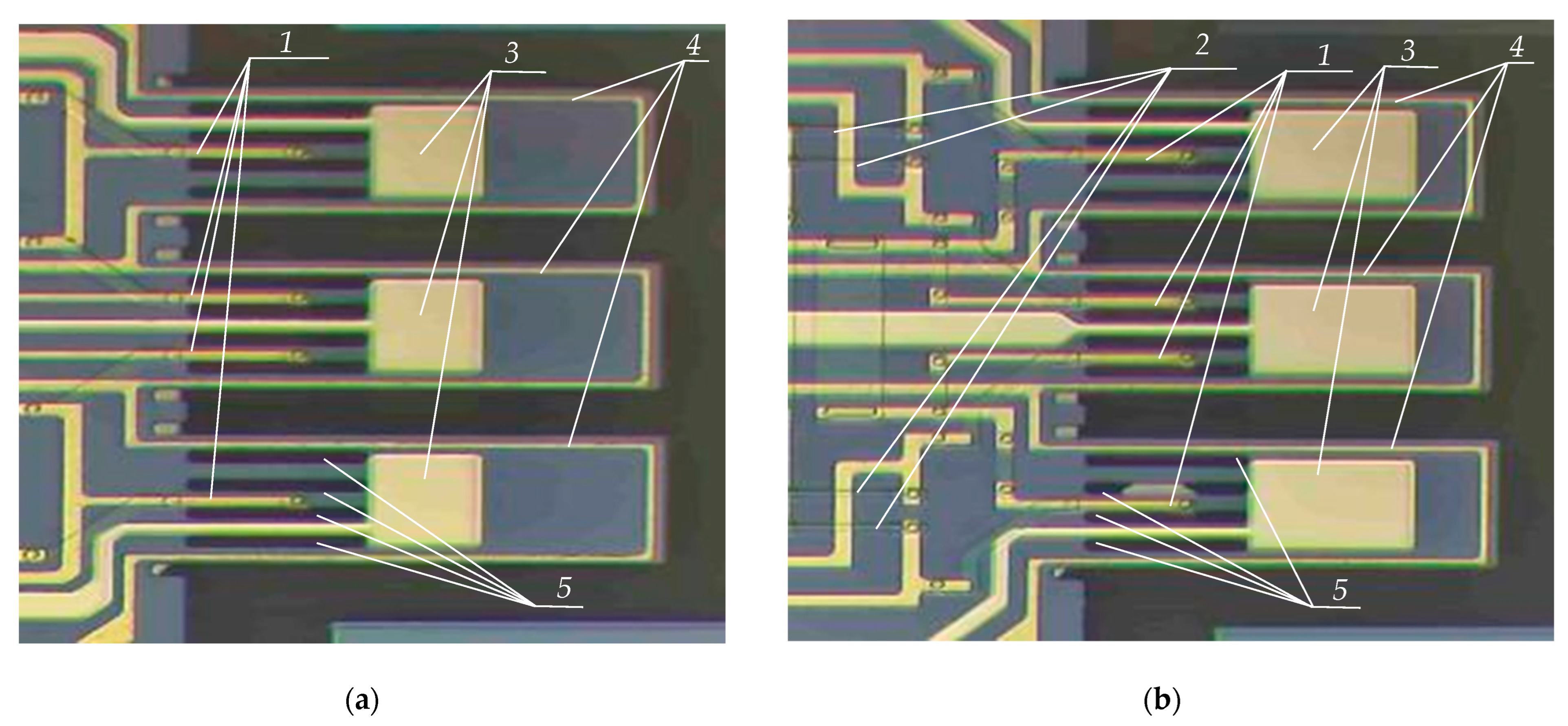
Figure 1. Topology of three-cantilever sensors selected for study: (a) four-piezoresistor sensor; (b) eight-resistor sensor. 1. Piezoresistors; 2. resistors; 3. golden pad. 4. heater; 5. rectangular holes.
Engproc 100 00060 g001
Figure 2. Schematic wiring of two piezoresistors and two resistors of triple-microcantilever sensor: (a) differential wiring in Wheatstone bridge of two piezoresistors and two passive resistors; (b) amplifying wiring in Wheatstone bridge of two different cantilevers and two passive resistors.
Engproc 100 00060 g002
Figure 3. Detection method idea with a three-zone sensor with four piezoresistors and four passive resistors connected in two bridges.
Engproc 100 00060 g003
Figure 4. Variants of wiring of four piezoresistors located on three microcantilevers: (a) amplifying circuit; (b) differential circuit.
Engproc 100 00060 g004
Figure 5. Electrodynamical model of the triple-microcantilever sensors: (a) mechanical part with the three cantilevers with four piezoresistors and common substrate; (b) Wheatstone bridge circuit with the four piezoresistors: 1. Cantilever1; 2. Cantilever2; 3. Cantilever3, 4. common substrate.
Engproc 100 00060 g005
Figure 6. Electrodynamical model of the triple-microcantilever sensor with 4 piezoresistors and 4 resistors: (a) mechanical part with the three cantilevers, piezoresistors, passive resistors, and common substrate; (b) first Wheatstone bridge circuit with piezoresistors R1 and R2 and resistors R5 and R6; (c) second Wheatstone bridge consisting of piezoresistors R3 and R4 and resistors R7 and R8. 1. Cantilever1; 2. Cantilever2; 3. Cantilever3, 4. common substrate.
Engproc 100 00060 g006
Figure 7. (a) Experimental setup for investigation of triple-cantilever sensor; (b) photo of a fabricated triple-microcantilever sensor. 1. Sensor with piezoelectric actuator and housing, 2. NI PXI system, 3. Digilent wave generator, 4. Monitor.
Engproc 100 00060 g007
Figure 8. Initial measurement results for the amplitude–frequency response of triple-microcantilever (C1, C2, C3) sensor with 4 piezoresistors: (a) amplitude–frequency characteristic of just four piezoresistors connected in a full Wheatstone bridge; (b) AFC of the full bridge comprising two resistors and two piezoresistors, each located on C1 and C2; (c) AFC of the full bridge comprising two resistors and two piezoresistors, each located on C1 and C3.
Engproc 100 00060 g008
Disclaimer/Publisher’s Note: The statements, opinions and data contained in all publications are solely those of the individual author(s) and contributor(s) and not of MDPI and/or the editor(s). MDPI and/or the editor(s) disclaim responsibility for any injury to people or property resulting from any ideas, methods, instructions or products referred to in the content.