Proceeding Paper

Crack Growth Modeling in CT Specimens: The Influence of Heat Treatment and Loading †

by
Raycho Raychev
1,2,*,
Ivanka Delova
1,2,
Tsvetomir Borisov
3 and
Yordan Mirchev
3
1
Department of Mechanics, Faculty of Mechanical Engineering, Technical University of Sofia Branch Plovdiv, 25 Ts. Diustabanov Str., 4000 Plovdiv, Bulgaria
2
Center of Competence “Smart Mechatronic, Eco- and Energy-Saving Systems and Technologies”, 4000 Plodiv, Bulgaria
3
Institute of Mechanics—Bulgarian Academy of Sciences (BAS), Acad. G. Bonchev St., bl. 4, 1113 Sofia, Bulgaria
*
Author to whom correspondence should be addressed.
Presented at the 14th International Scientific Conference TechSys 2025—Engineering, Technology and Systems, Plovdiv, Bulgaria, 15–17 May 2025.
Eng. Proc. 2025, 100(1), 61; https://doi.org/10.3390/engproc2025100061
Published: 21 July 2025

Abstract

This study provides a combined numerical and analytical investigation of fatigue crack growth in compact tension specimens made of 42CrMo4 steel. Through simulations in ANSYS Workbench (SMART Crack Growth module) and numerical modeling in MATLAB, the model is validated by comparing its results with the standard ASTM E399 and Paris’ law relationships. The effect of heat treatments and loading on crack growth rate was investigated. The results confirm the model’s applicability in predicting fatigue behavior in the linear–elastic region.

1. Introduction

Fatigue crack growth is one of the main causes of failure of structural members subjected to cyclic loads. Accurate modelling of this process is essential for reliable assessment of the residual life and structural integrity of critical components. One of the widely used approaches for validating numerical models is the analysis of a standard compact specimen for which validated analytical relationships are available.
This paper presents numerical modelling of fatigue crack growth in a compact 42CrMo4 steel specimen with different heat treatments. Finite element methods using ANSYS Workbench (version 2019R1) and analytical relationships based on the ASTM E399 [1] standard and Paris’ law are used. By comparing the results of the two approaches, the correctness of the numerical model is validated. Emphasis is placed on the influence of geometric parameters, applied load, and heat treatment on crack growth rate and the estimation of critical crack depth.
A range of papers are devoted to research related to modeling and computer simulations in compact specimens.
The influence of the stress ratio (R) on fatigue crack growth in metallic materials has been investigated through the analysis of compact tension specimens in [2,3,4,5,6]. Both classical relationships and modern models based on energy principles and crack closure effects are considered. Experimental and numerical results show that the stress ratio R has a significant impact on the crack growth rate and is a key parameter in assessing the fatigue life of structures under variable cyclic loading.
One study [7] explores fatigue crack propagation in modified compact tension (CT) specimens subjected to variable amplitude and mixed-mode loading conditions, using a hybrid approach that combines finite element modeling and machine learning (ML).
Other studies [8,9,10] consolidate key research on fatigue crack growth in metallic materials, with a focus on the role of the stress ratio (R), crack tip mechanics, and modeling approaches. A unified two-parameter approach is examined, combining the maximum stress intensity factor (Kmax) and the stress intensity range (ΔK) as a more accurate representation of crack behavior under various conditions. The influence of residual stresses, cyclic plasticity, and local elasto-plastic fields at the crack tip is analyzed. Finite element methods and experimental data are utilized to validate models for alloys such as Ti–6Al–4V, 2024-T351, and structural steels, thereby contributing to enhanced fatigue life prediction of engineering components.
Studies [11,12,13,14] have explored modern numerical and analytical approaches for analyzing crack growth under fatigue and fretting loading conditions. Emphasis is placed on the application of advanced methods such as PolyXFEM, Linear Elastic Fracture Mechanics (LEFM), extended maximum tangential stress criteria, and adaptive mesh generation techniques. The influence of residual stress, loading phase difference, and crack initiation characteristics on crack trajectory and lifetime is thoroughly investigated. The proposed methodologies demonstrate strong agreement with experimental data and provide more reliable predictions of the fatigue life of engineering components under complex loading scenarios.
Studies [15,16,17,18,19] have consolidated advanced approaches for modeling fatigue crack growth under mixed-mode loading in metallic structures, steels, and brittle materials such as rocks. Methods such as linear smoothed XFEM, 2D finite element simulations, equivalent stress intensity factor formulations, and hybrid FEM-DEM at the grain scale are employed. The effects of geometry, loading angle, material strength, and heterogeneity on crack path, propagation rate, and fatigue life are analyzed. The results show strong agreement with experimental observations and provide robust tools for fatigue life prediction under complex service conditions.
Refs. [20,21,22,23,24] present numerical simulations of fatigue crack growth under mixed-mode loading, focusing on the use of ANSYS APDL Release 19.2 (version 2019) and methods such as SMART Crack Growth and XFEM. The effects of geometric features, holes, thickness, and loading angles on crack trajectory and fatigue life are analyzed. Various configurations are investigated, including three-point bending beams and modified compact tension specimens. All studies demonstrate that the position of the hole and the loading characteristics significantly influence crack direction and SIFs, and the results are consistent with experimental observations.
Ref. [25] presents a computational model for analyzing fatigue crack initiation and propagation under cyclic contact loading, emphasizing pitting formation on gear tooth flanks. The model combines finite element analysis with short crack growth theory, using the Virtual Crack Extension (VCE) method for simulating crack growth. Crack initiation is evaluated via strain-life (e–N) methods, including SWT and Morrow corrections. The results show that initial crack position, orientation, contact movement, and lubrication significantly influence crack trajectory and pitting formation. The model enables fatigue life prediction of gears under realistic rolling–sliding contact conditions.
Refs. [26,27,28] introduce innovative approaches for predicting fatigue crack growth under mixed-mode loading using a combination of numerical simulations, experimental validation, and machine learning. This research focuses on CTS and CT specimen geometries with varied loading conditions and repair strategies such as stop-hole techniques. Stress intensity factors (KI, KII) and crack propagation paths are analyzed via FEM, while neural networks are employed for lifetime prediction. The results confirm the high accuracy and effectiveness of these models for structural health monitoring and extending the service life of critical components.

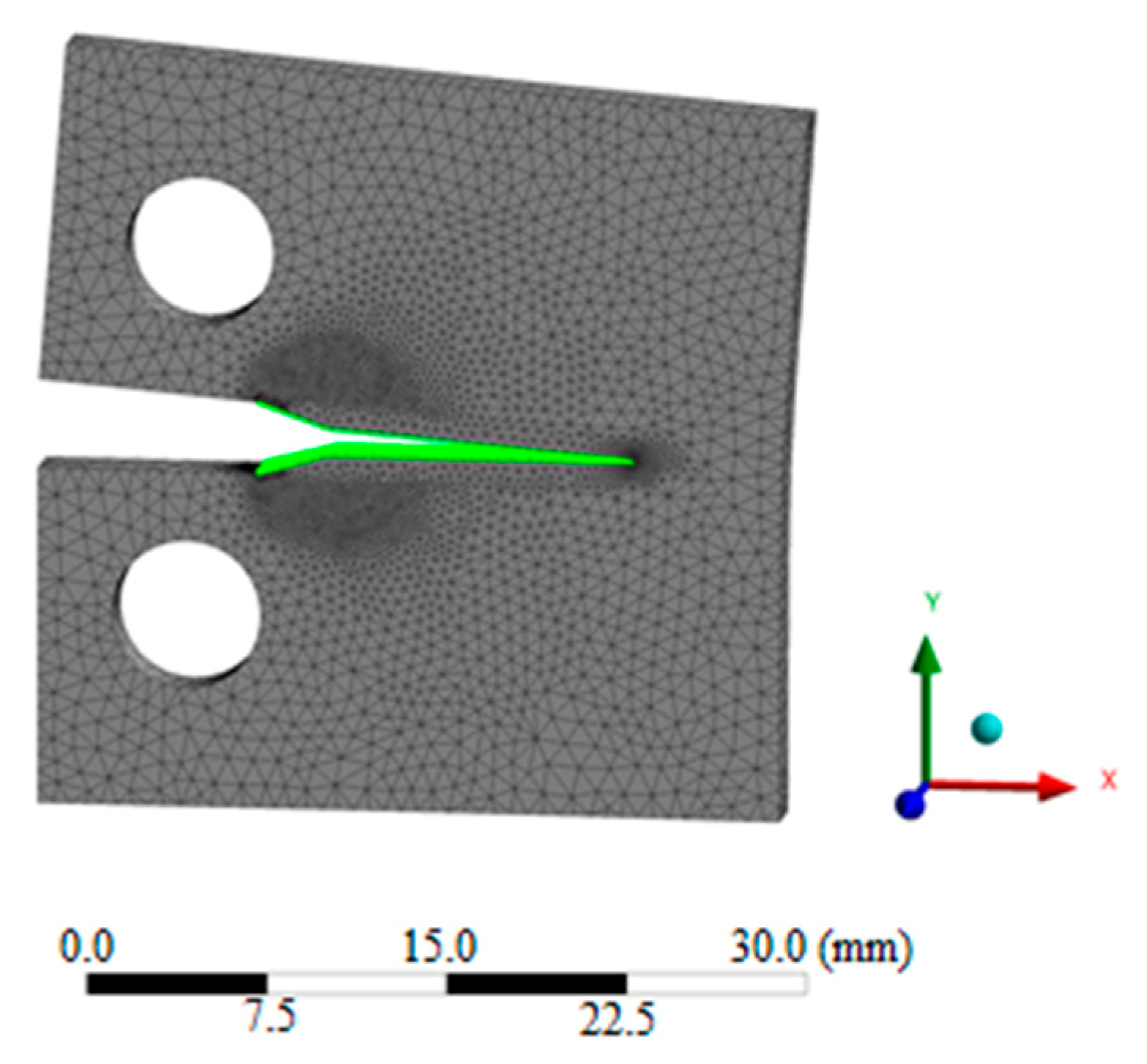
2. Numerical Modeling

To justify the application of numerical analysis using specialized software, simulations have been carried out with a compact model for which validated empirical relationships exist, allowing validation of the results obtained. For the purpose of the analysis, a compact specimen of certain dimensions subjected to static and dynamic loading was considered. The analytical method uses the following empirical equation:
K I = P B W f a W ,
where:
KI—stress intensity factor, [MPa m ];
P—applied load [N];
B—specimen thickness [mm];
W—specimen width [mm];
a—crack length [mm];
f(a/W)—empirical correction function. According to ASTM E399, it is given by the following approximate equation:
f a W = 2 + a W 1 a W 3 / 2 . 0.886 + 4.64 a W 13.32 a W 2 + 14.72 a W 3 5.6 a W 4 .
Figure 1 depicts the compact specimen that is the subject of numerical modeling and simulations.
The static analysis was performed at different ratios of the geometrical dimensions of the specimen. Realistic boundary conditions and material constants typical of 42CrMo4 steel were applied in the study. The summarized results under static loading are presented in Table 1.
The chosen applied load of P = 2000 N maintains stress within the linear–elastic range suitable for validating the numerical model against analytical relationships. This value ensures that the material remains within the region of linear–elastic behavior, which is a prerequisite for the application of linear–elastic failure mode (LEFM) analysis. This avoids non-linear effects that would occur at higher loads and complicate the analysis.
Figure 2 visualizes the result of the static analysis with ANSYS Workbench (version 2019R1) SMART Crack Growth.
The analysis of the results shows that as the crack length—and thereby the a/W ratio—increase, a monotonic increase in the stress intensity factor KIC is observed, in both the theoretical approach and in the numerical simulation. This behavior is expected since longer cracks lead to higher stress concentration at the crack face.
The differences between the theoretical and numerical KIC values are relatively small and remain below 2% over the entire range studied. The maximum observed deviation was 1.998% at a/W = 0.45, with a minimum deviation of 0.088% at a/W = 0.41. This confirms the high accuracy of the simulation model and correctly set boundary conditions.
After validating the numerical model under static loading and establishing good agreement with the analytical results, the focus of the study turned to the behavior of the specimen under dynamic loads. The reason for this is that in real operating conditions, structural elements are rarely loaded only statically, but are more often subjected to cyclic and impact loads leading to material fatigue.
The SMART Crack Growth module built into ANSYS Workbench (version 2019R1) was used to simulate fatigue crack growth, allowing crack propagation to be tracked under specified cyclic loads. Using this module, the crack growth rate can be estimated as a function of the number of cycles using an approach based on Paris’ law that is valid for linear fracture mechanics (LEFM).
Paris’ law describes the crack growth rate versus the amplitude of the stress intensity factor. The basic formula has the following form [29]:
d a d N = C . Δ K m ,
where:
da/dN—crack growth rate per cycle (m/cycle);
ΔK—stress intensity factor amplitude;
C, m—material constants (depend on heat treatment);
The amplitude ΔK is determined by the following equation:
Δ K = K m a x K m i n = Δ σ . π a . Y a W ,
where:
Δσ = σmaxmin—stress amplitude;
a—crack length;
Y(a/W)—correction geometric function set depending on the a/W ratio;
Kmax and Kmin—intensity coefficients at maximum and minimum loads in the cycle.
The total number of cycles N until a critical crack length ac is reached is determined by integrating the Paris equation:
N = a 0 a c 1 C Δ K a m d a .
In addition to the simulations, numerical modeling was performed in MATLAB (version R2016a) to validate the results and evaluate the influence of various factors on crack growth. MATLAB was used to implement an algorithm based on Paris’ law with inputs such as the geometric dimensions of the specimen, the mechanical characteristics of the material, and material constants.
The simulations in ANSYS Workbench (version 2019R1) and the parallel numerical modeling in MATLAB (version R2016a) were implemented under different load values and various heat treatment modes of 42CrMo4 steel, including the no heat treatment condition, oil quenching, water quenching and cementation with quenching.
Three different nominal stress levels were used for loading: 1.63 MPa, 3.26 MPa and 4.89 MPa, which correspond to different operating modes covering low, medium, and high cyclic loading. The choice of these values ensures that the material remains within the range of linear–elastic behavior applicable to Paris’ law.
The following inputs were used to perform the simulations and numerical modeling:
-
Specimen width: W = 25 mm;
-
Specimen thickness: B = 2.5 mm;
-
Initial crack length: a = 6 mm;
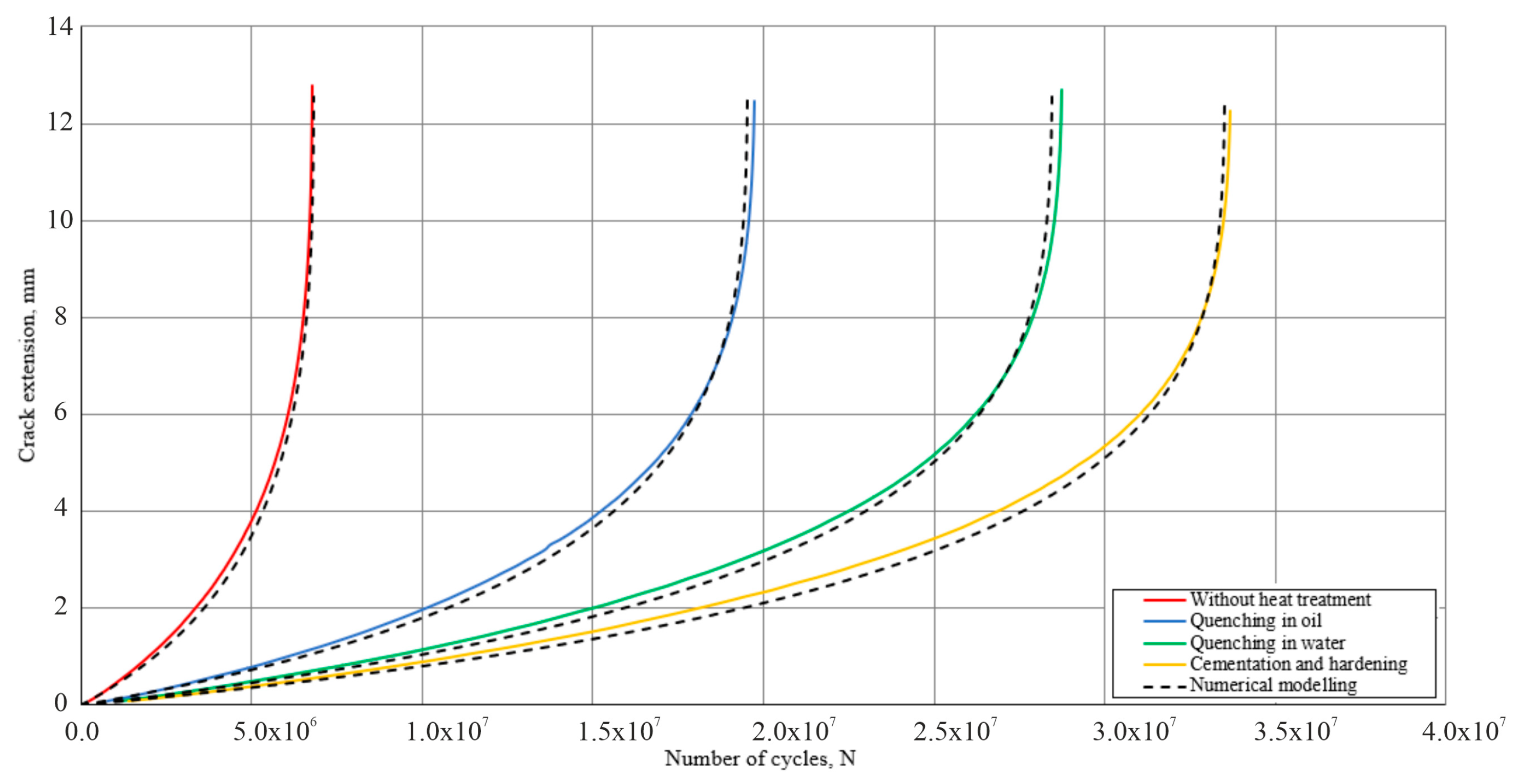
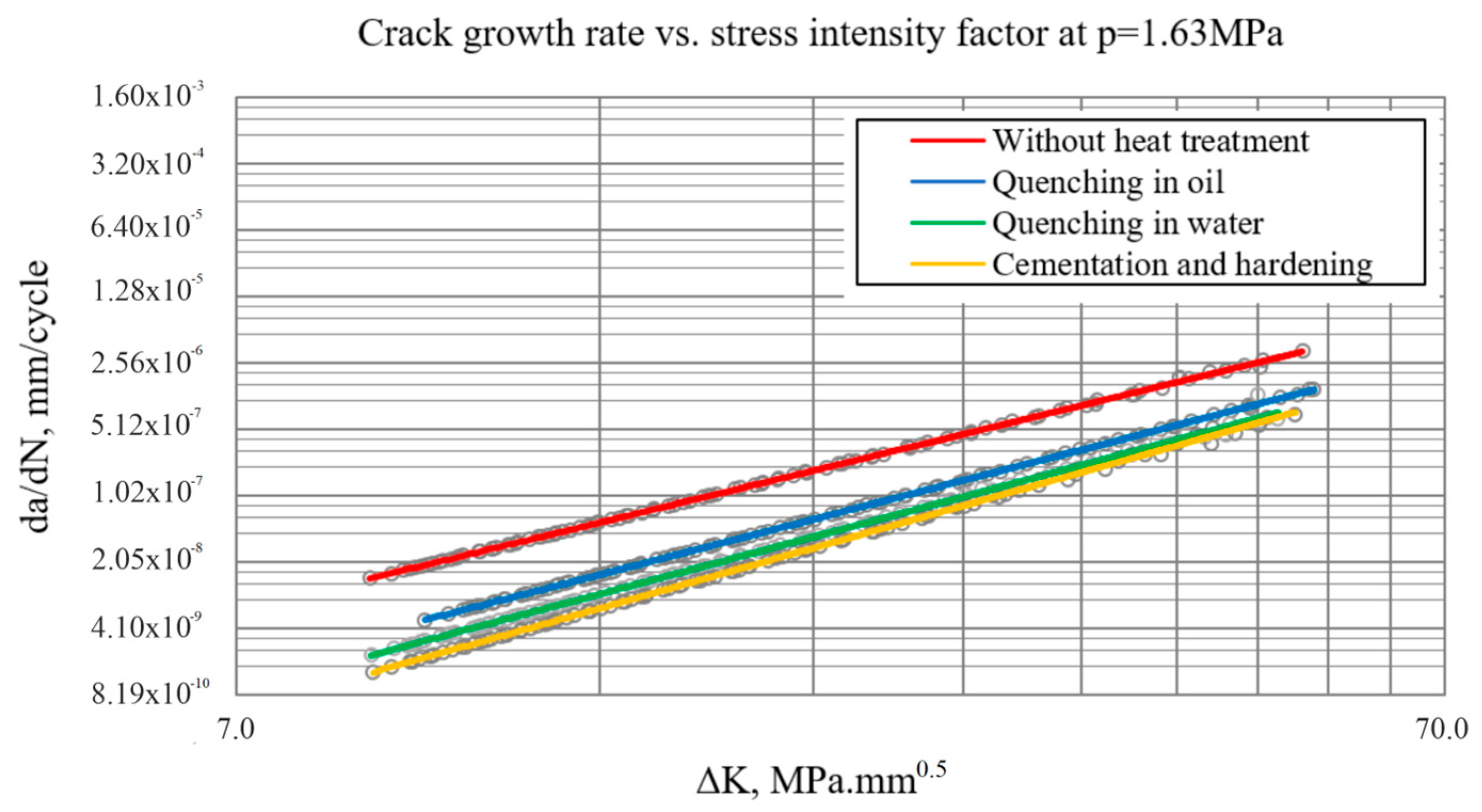
The initial crack length was selected in accordance with the recommendations of ASTM E647, which specifies the allowable range for the initial crack length relative to the specimen dimensions. An initial length of 6 mm provides valid conditions for the application of LEFM and ensures that the crack will develop in a stable mode under the applied load.
Table 2 presents the values of the material constants C and m from Paris’ law.
As shown in Table 2, for all values of material constants corresponding to the heat treatments considered, a stress ratio (R) of 0.1 was assumed, commonly used as a standard in fatigue behavior evaluations.

3. Research Results

Figure 3, Figure 4 and Figure 5 present a comparison of the numerical modeling results in MATLAB and the simulations in ANSYS Workbench (version 2019R1) to assess the agreement between the two approaches.
The graphs reflect the way in which loading affects the rate of crack growth and the overall service life of the specimen.
At the lowest stress level (1.63 MPa), growth is slow and uniform over most of the component life, with acceleration occurring only in the terminal phase. At the medium stress level (3.26 MPa), growth accelerates earlier, with the number of cycles required to reach the critical crack length being significantly less. At the highest stress level (4.89 MPa), growth is very intense from the initial stages, resulting in a very limited service life.
In all three cases, excellent agreement was observed between MATLAB (version R2016a) numerical modeling results and ANSYS Workbench (version 2019R1) simulations. This confirms the validity of the adopted theoretical models and the correctness of the numerical analysis.
Table 3 presents the largest percentage deviations between simulation and numerical modeling.
The main reasons for the percentage deviations are:
-
Difference in the methodology for calculating ΔK—in ANSYS Workbench (version 2019R1), the calculation of the stress intensity factor ΔK is based on the finite element method;
-
Simplification of the real geometry and boundary conditions—the numerical model in ANSYS Workbench (version 2019R1) includes three-dimensional geometry, real fixtures, and loading conditions. The analytical approach in MATLAB (version R2016a) uses standard geometry functions and simplified boundary conditions (standard CT specimen), which lowers the resulting ΔK values.
-
Real stress concentrations—in ANSYS Workbench (version 2019R1) simulations, there may be local stress increases (e.g., around holes, transitions, edges, and cracks) that are not adequately accounted for in the analytical model.
-
Method for determining the coefficients—standard formulas are derived experimentally and analytically for strictly defined specimens (e.g., CT specimens with ideal geometry). The real numerical model has its own specific geometry that differs from the standard specimen.
Figure 6, Figure 7 and Figure 8 present the results of numerical simulations, performed in the ANSYS Workbench (version 2019R1) environment using the SMART Crack Growth function, in graphical form.
In all the cases considered, a characteristic linear relationship on a logarithmic scale between da/dN and ΔK is observed, which is consistent with Paris’ law for fatigue crack growth. This confirms that the 42CrMo4 material, under the considered heat treatment conditions, exhibits behavior obeying the principles of LEFM.
The results show that as the applied nominal stress increases, the crack growth rate increases significantly. At the lowest stress level (1.63 MPa), crack growth is slow and occurs gradually during most of the component’s life.
At the medium load (3.26 MPa), the acceleration of growth occurs at an earlier stage, and at the highest stress load (4.89 MPa), the crack starts to grow at a high rate from the beginning of the load, resulting in a significant reduction in the remaining service life.
Heat treatment has a significant effect on the crack growth rate. Specimens subjected to cementation and hardening show the lowest growth rate at a given ΔK, which is an index of increased material resistance to fatigue failure. On the other hand, specimens without heat treatment exhibit significantly faster crack growth and, consequently, shorter lifetimes. Quenching in water results in better resistance compared to quenching in oil.
The simulation results clearly show that loading and heat treatment are key factors influencing the material’s behavior under fatigue loading. Numerical modeling in ANSYS proves its effectiveness for predicting crack growth rates and can serve as a reliable tool for estimating the residual life of structural members.

4. Conclusions

The object of this paper is to investigate the effectiveness and accuracy of a combined approach using numerical simulations in ANSYS Workbench (SMART Crack Growth module) and analytical modeling in MATLAB to predict fatigue crack growth in compact 42CrMo4 steel specimens. The analysis demonstrated strong consistency between numerical and analytical results, with deviations of less than 5%. It is confirmed that, with increasing applied load, the crack growth rate increases significantly, thereby shortening the overall specimen lifetime.
The studies clearly show the significant influence of heat treatment on the fatigue resistance of the material. Specimens subjected to cementation and hardening exhibit the lowest crack growth rate and the longest service life, while non-heat-treated specimens have significantly faster growth and, correspondingly, a shorter service life. Quenching in water provides superior resistance to quenching in oil.
The results confirm the applicability of the model based on Paris’ law and ASTM standards E399 and E647 for evaluating fatigue behavior in the linear–elastic region. This model can be successfully used to predict the residual life and ensure the reliability of engineering components subjected to cyclic loads.
An additional advantage of the proposed methodology is the potential for early identification of critical cracks and the prevention of potential failures in engineering practice. A detailed understanding of fatigue processes and the influence of various factors, such as heat treatment and applied load, enables the optimization of design solutions and material selection. These approaches are essential for enhancing the safety and extending the service life of critical components subjected to cyclic mechanical loads.
The presented research highlights the importance of integrating advanced numerical methods and analytical approaches to provide higher accuracy and reliability in fatigue analysis of materials. This integrated methodology can serve as a basis for more in-depth studies on different types of materials and more complex loading conditions. Future research could further address the influence of different geometries, changes in environmental conditions, and long-term crack behavior under realistic service conditions. The results and methodologies obtained could find application not only in the mechanical engineering and automotive sectors, but also in aviation and railway industries, where component safety and reliability are critical.

Author Contributions

Conceptualization, R.R. and Y.M.; methodology, Y.M.; software, R.R.; validation, I.D. and T.B.; formal analysis, R.R.; investigation, I.D. and T.B.; resources, T.B.; data curation, Y.M.; writing—original draft preparation, R.R. and I.D.; writing—review and editing, Y.M. and T.B.; visualization, I.D.; supervision, R.R. and Y.M.; project administration, R.R.; funding acquisition, R.R. and I.D. All authors have read and agreed to the published version of the manuscript.

Funding

This research was funded by the European Regional Development Fund within the OP “Research, Innovation and Digitalization Programme for Intelligent Transformation 2021–2027”, Project No. BG16RFPR002-1.014-0005 Center of competence “Smart Mechatronics, Eco- and Energy Saving Systems and Technologies”.

Institutional Review Board Statement

Not applicable.

Informed Consent Statement

Not applicable.

Data Availability Statement

Data are contained within the article.

Conflicts of Interest

The authors declare no conflicts of interest.

References

  1. ASTM E399; Standard Test Method for Linear-Elastic Plane-Strain Fracture Toughness KIC of Metallic Materials. ASTM International: West Conshohocken, PA, USA, 2013.
  2. Iranpour, M.; Taheri, F. On the effect of stress intensity factor in evaluating the fatigue crack growth rate of aluminum alloy under the influence of compressive stress cycles. Int. J. Fatigue 2012, 43, 1–11. [Google Scholar] [CrossRef]
  3. Li, H.; Yang, S.; Zhang, P.; Liu, Y.; Wang, B.; Zhang, Z. Material-independent stress ratio effect on the fatigue crack growth behavior. Eng. Fract. Mech. 2022, 259, 108116. [Google Scholar] [CrossRef]
  4. White, P.; Barter, S.; Medhekar, N. Comparison of fatigue crack growth stress ratio effects under simple variable amplitude loading using fractographic and strain measurements. Int. J. Fatigue 2018, 112, 240–252. [Google Scholar] [CrossRef]
  5. Sun, C.; Lei, Z.; Hong, Y. Effects of stress ratio on crack growth rate and fatigue strength for high cycle and very-high-cycle fatigue of metallic materials. Mech. Mater. 2014, 69, 227–236. [Google Scholar] [CrossRef]
  6. Alshoaibi, A.M. Fatigue Crack Growth Analysis in Modified Compact Tension Specimen with Varying Stress Ratios: A Finite Element Study. Appl. Sci. 2023, 13, 13160. [Google Scholar] [CrossRef]
  7. Santos, B.; Infante, V.; Barros, T.; Baptista, R. Study of fatigue crack propagation on modified CT specimens under variable amplitude loadings using machine learning. Int. J. Fatigue 2024, 184, 108332. [Google Scholar] [CrossRef]
  8. Pook, P. The linear elastic analysis of cracked bodies and crack paths. Theor. Appl. Fract. Mech. 2015, 79, 34–50. [Google Scholar] [CrossRef]
  9. Noroozi, A.; Glinka, G.; Lambert, S. A study of the stress ratio effects on fatigue crack growth using the unified two-parameter fatigue crack growth driving force. Int. J. Fatigue 2007, 29, 1616–1633. [Google Scholar] [CrossRef]
  10. Sadananda, K.; Vasudevan, A. Fatigue crack growth behavior of titanium alloys. Int. J. Fatigue 2005, 27, 1255–1266. [Google Scholar] [CrossRef]
  11. Alshoaibi, A.M.; Fageehi, Y.A. A Robust Adaptive Mesh Generation Algorithm: A Solution for Simulating 2D Crack Growth Problems. Materials 2023, 16, 6481. [Google Scholar] [CrossRef] [PubMed]
  12. Wang, C.; Pereira, K.; Wang, D.; Zinovev, A.; Terentyev, D.; Wahab, M. Fretting fatigue crack propagation under out-of-phase loading conditions using extended maximum tangential stress criterion. Tribol. Int. 2023, 187, 108738. [Google Scholar] [CrossRef]
  13. Huynh, H.; Nguyen, M.; Cusatis, G.; Tanaka, S.; Bui, T. A polygonal XFEM with new numerical integration for linear elastic fracture mechanics. Eng. Fract. Mech. 2019, 213, 241–263. [Google Scholar] [CrossRef]
  14. Wang, C.; Fan, K.; Li, C.; Wahab, M. Prediction of the effect of shot peening residual stress on fretting fatigue behavior. Int. J. Fatigue 2023, 176, 107909. [Google Scholar] [CrossRef]
  15. Surendran, M.; Natarajan, S.; Palani, G.; Bordas, S. Linear smoothed extended finite element method for fatigue crack growth simulations. Eng. Fract. Mech. 2019, 206, 551–564. [Google Scholar] [CrossRef]
  16. Rozumek, D.; Marciniak, Z.; Lesiuk, G.; Correia, J. Mixed mode I/II/III fatigue crack growth in S355 steel. Procedia Struct. Integr. 2017, 5, 896–903. [Google Scholar] [CrossRef]
  17. Alshoaibi, A.M.; Fageehi, Y. 2D finite element simulation of mixed mode fatigue crack propagation for CTS specimen. J. Mater. Res. Technol. 2020, 9, 7850–7861. [Google Scholar] [CrossRef]
  18. Li, X.; Li, H.; Liu, L.; Liu, Y.; Ju, M.; Zhao, J. Investigating the crack initiation and propagation mechanism in brittle rocks using grain-based finite-discrete element method. Int. J. Rock Mech. Min. Sci. 2020, 127, 104219. [Google Scholar] [CrossRef]
  19. Nejad, R.M.; Liu, Z. Analysis of fatigue crack growth under mixed-mode loading conditions for a pearlitic Grade 900A steel used in railway applications. Eng. Fract. Mech. 2021, 247, 107672. [Google Scholar] [CrossRef]
  20. Alshoaibi, A.M. Computational Simulation of 3D Fatigue Crack Growth under Mixed-Mode Loading. Appl. Sci. 2021, 11, 5953. [Google Scholar] [CrossRef]
  21. Alshoaibi, A.M.; Fageehi, Y.A. 3D modelling of fatigue crack growth and life predictions using ANSYS. Ain Shams Eng. J. 2022, 13, 101636. [Google Scholar] [CrossRef]
  22. Alshoaibi, A.M. Numerical Modeling of Crack Growth under Mixed-Mode Loading. Appl. Sci. 2021, 11, 2975. [Google Scholar] [CrossRef]
  23. Fageehi, Y.A.; Alshoaibi, A.M. Numerical Simulation of Mixed-Mode Fatigue Crack Growth for Compact Tension Shear Specimen. Adv. Mater. Sci. Eng. 2020, 2020, 5426831. [Google Scholar] [CrossRef]
  24. Bashiri, A. 2D and 3D numerical simulation of fatigue crack growth path and life predictions of a linear elastic. Mater. Sci. 2021, 39, 285–297. [Google Scholar] [CrossRef]
  25. Fajdiga, G.; Sraml, M. Fatigue crack initiation and propagation under cyclic contact loading. Eng. Fract. Mech. 2009, 76, 1320–1335. [Google Scholar] [CrossRef]
  26. Ayatollahi, M.; Razavi, N.; Yahya, M. Mixed mode fatigue crack initiation and growth in a CT specimen repaired by stop hole technique. Eng. Fract. Mech. 2015, 145, 115–127. [Google Scholar] [CrossRef]
  27. Antunes, F.; Branco, R.; Ferreira, J.; Borrego, L. Stress Intensity Factor Solutions for CTS Mixed Mode Specimen. Fract. Struct. Integr. 2019, 13, 676–692. [Google Scholar] [CrossRef]
  28. Zhao, Y.; Liu, Y.; Xu, Z. Statistical learning prediction of fatigue crack growth via path slicing and re-weighting. Theor. Appl. Mech. Lett. 2023, 13, 100477. [Google Scholar] [CrossRef]
  29. Paris, P.; Erdogan, F. A Critical Analysis of Crack Propagation Laws. ASME J. Basic Eng. Dec. 1963, 85, 528–533. [Google Scholar] [CrossRef]
Figure 1. A schematic of the compact specimen (all dimensions are in mm).
Engproc 100 00061 g001
Figure 2. Visualizing crack growth in ANSYS Workbench (version 2019R1) simulation.
Engproc 100 00061 g002
Figure 3. Visualization of crack growth at p = 1.63 MPa.
Engproc 100 00061 g003
Figure 4. Visualization of crack growth at p = 3.26 MPa.
Engproc 100 00061 g004
Figure 5. Visualization of crack growth at p = 4.89 MPa.
Engproc 100 00061 g005
Figure 6. Visualization of crack growth vs. ΔK at p = 1.63 MPa.
Engproc 100 00061 g006
Figure 7. Visualization of crack growth vs. ΔK at p = 3.26 MPa.
Engproc 100 00061 g007
Figure 8. Visualization of crack growth vs. ΔK at p = 4.89 MPa.
Engproc 100 00061 g008
Table 1. Stress Intensity Factor Comparison for Various Crack Length Ratios.
Load,
P [N]
Thickness,
B [m]
Width,
W [m]
Length,
a [m]
Ratio
(a/W)
KI—Theoretical,
MPa.m0.5
KI—Simulations,
MPa.m0.5
Deviation,
%
20000.00250.0250.00625
0.00725
0.00825
0.00925
0.01025
0.01125
0.01225
0.01325
0.01425
0.01525
0.25
0.29
0.33
0.37
0.41
0.45
0.49
0.53
0.57
0.61
4.913
5.464
6.058
6.714
7.456
8.317
9.342
10.59
12.15
14.16
4.903
5.491
5.982
6.721
7.463
8.484
9.283
10.45
12.11
14.08
0.205
0.477
−1.252
0.097
0.088
1.998
−0.639
−1.389
−0.465
−0.526
Table 2. Material Constants for Paris’ Law under Various Heat Treatments.
Heat TreatmentC (mm/cycle)mStress Ratio
Without heat treatment1.5 × 10−113.1R = 0.1
Quenching in oil2.5 × 10−123.3
Quenching in water1.2 × 10−123.4
Cementation and hardening5.0 × 10−133.6
Table 3. Largest Deviations between Simulation and Numerical Modeling Results.
Heat TreatmentLoad, MPaLargest Deviation in %
Without heat treatment1.633.73
Without heat treatment3.264.17
Without heat treatment4.892.83
Quenching in oil1.633.42
Quenching in oil3.261.64
Quenching in oil4.894.44
Quenching in water1.633.93
Quenching in water3.261.82
Quenching in water4.891.78
Cementation and hardening1.632.95
Cementation and hardening3.263.41
Cementation and hardening4.894.9
Disclaimer/Publisher’s Note: The statements, opinions and data contained in all publications are solely those of the individual author(s) and contributor(s) and not of MDPI and/or the editor(s). MDPI and/or the editor(s) disclaim responsibility for any injury to people or property resulting from any ideas, methods, instructions or products referred to in the content.

