Abstract
Off-the-shelf consumer-grade smart glasses are being increasingly used in extended reality and brain–computer interface applications that are based on the detection of visually evoked potentials from the user’s brain. The displays of these kinds of devices can be based on different technologies, which may affect the nature of the visual stimulus received by the user. This aspect has substantial impact in the field of applications based on wearable sensors and devices. We measured the optical output of three models of smart glasses with different display technologies using a photo-transducer in order to gain insight on their exploitability in brain–computer interface applications. The results suggest that preferring a particular model of smart glasses may strongly depend on the specific application requirements.
1. Introduction
Emerging brain–computer interfaces (BCIs) are being extensively investigated in the scientific community [1]. BCIs provide a novel means of communication which relies on the direct detection of brain signals. The applications of BCIs are oriented to impaired and able-bodied people, with several already explored applications such as robot control [2], industrial inspection [3], and neurological rehabilitation [4,5,6]. Among various paradigms, the so-called reactive BCI, in which the user is exposed to a stimulus and the evoked brain response is detected, are the best-performing ones [7,8,9]. In particular, BCIs based on visually evoked potentials (VEPs) are well suited for communication and control applications [3,10,11]. Visual stimulation in VEP-BCI can be performed by means of off-the-shelf smart glasses, which can generate icons of different colour, shape, position and blinking rate in the user’s field of view [3,12]. Smart glasses based on different display technologies are available on the market. Typically, smart glasses exploit video see-through or optical see-through technology. The former consists of displaying virtual objects in superposition with a video recording of the real environment, whereas the latter exploits semi-transparent displays allowing normal vision with superimposed virtual elements [13]. There exist commercial devices that rely on either liquid crystal displays (LCDs) with active matrices of poly-crystalline silicon thin-film-transistors, silicon-based organic light emitting diode (OLED) matrices, planar waveguides, or other technologies at various development stages [14,15,16]. Independently of the display technology, the visual stimuli must have a number of specific characteristics to be suitable for VEP-BCI applications. These characteristics may strongly depend on the technology and the implementation of the smart glasses, first of all on the ability of generating stimuli with specific and distinguishable harmonic contents. In this paper, we report and discuss measurements of the optical output of smart glasses based on three different technologies and discuss the results in terms of VEP-BCI applications.
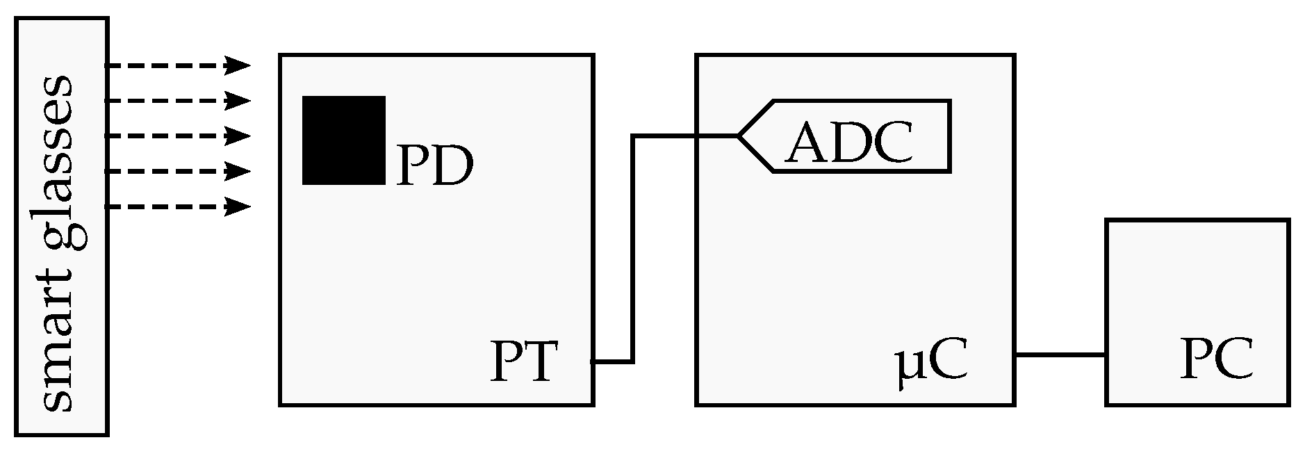
2. Materials and Methods
We characterised three models of commercially-available smart glasses based on different technology: (i) Epson BT-200, (ii) Epson BT-350, and (iii) Microsoft Hololens. The BT-200 employs an LCD display, the BT-350 employs an OLED display, and the Hololens’s display is based on waveguides. The presented devices are representative of the most recent consumer-grade technologies available on the market. The smart glasses were programmed to generate a white rectangular icon blinking at frequency f on one lens. To characterise the optical output of the above-mentioned smart glasses, we implemented a phototransducer (our approach is similar to the one described by international standards series IEC 62087 concerning measurement of the brightness of displays [17]). The photo-transducer (PT), schematically shown in Figure 1, was based on a commercial photodiode (OPT-101) integrated with a transimpedance amplifier [18]. The PT was battery-powered to avoid power line interference. The microcontroller C STM32F401RE [19] was used to measure the output voltage of PT and to transmit the measured values to a PC. The microcontroller’s ADC has a resolution of 12 bit and was operated at a sampling frequency of 1 kHz. The transducer PT was placed in front of the smart glasses display with the blinking icon extending on the whole sensor area. In each case, the positioning was empirically determined by looking for the maximum measurable voltage, so that the sensor was uniformly illuminated by the icon.
Figure 1.
Schematic representation of the experiment, with the smart glasses and the phototransducer PT. The dashed arrows represent the light coming from the blinking icon generated by the smart glasses. The filled black square represents the PD-sensitive area.
In order to obtain meaningful results, we checked the overall bandwidth of our phototransducer by measuring a 12 square-wave optical signal generated with an LED driven by a function generator SRS DS360. The DS360 had a nominal rise time of [20], whereas the LED rise time was comparably negligible, making the test signal bandwidth large enough with respect to the PT’s bandwidth (limited by the ADC). The 1 LED series resistance was high enough to achieve a negligible current load for the signal generator, thus avoiding signal distortion. These preliminary measurements highlighted a discrepancy between the nominal and the measured harmonic ratios for a test square wave of less than 0.5% up to the 11th component of the measured signal .
The optical output of each of the tested smart glasses was recorded in a dark room for 10 and analysed up to a frequency of 100 , high enough for the requirements of VEP-BCI applications. This maximum frequency was well below the ADC’s Nyquist frequency to avoid artefacts due to aliasing.
3. Results
Figure 2 shows the optical output, represented by the ADC voltage , of the three smart glasses when programmed to generate a blinking icon (a square wave visual stimulus) at . The signals in the time domain are shown in Figure 2a–c within a time frame of 1 . The corresponding plots in the frequency domain are shown in Figure 2d–f in the range from 0 –100 . From Figure 2a–c, it can be seen that the three smart glasses, programmed to generate the same nominal signal, produce substantially different outputs. In particular, the BT-200 (LCD) produces a rather symmetric wave profile, whereas the BT-350 (OLED) produces a strongly asymmetric profile, but in both cases, the intensity of their output changes in a smooth way. By contrast, the output of the Hololens smart glasses appears to be composed of a series of fast pulses. Furthermore, there are three distinct sets of pulses with different intensities, corresponding to the red, green, and blue colour components, as verified with separate measurements. Finally, in the time-domain plots of Figure 2a,b, the waveforms have different rise and fall profiles, probably related to the different on and off switching times of the display elements.
Figure 2.
Optical output of the characterised smart glasses. Time domain signals of BT-200 (a), BT-350 (b), and Hololens (c). Frequency domain spectra of BT-200 (d), BT-350 (e), and Hololens (f). Each spectrum (d–f) is normalised to its first harmonic.
Figure 2d–f show the output harmonic content of the tested smart glasses. The BT-200 and BT-350 present a rather well-defined harmonic content, whereas the Hololens does not allow one to distinguish any frequency component, whether the fundamental at frequency f or the higher harmonics.
Here, the asymmetric distortion seen in the time domain plots of Figure 2a,b is reflected in the spectra shown in Figure 2d,e, which in addition to the odd-harmonics of a symmetric square-wave ( 12 , 36 , ...), also contain even harmonics ( 24 , 48 , ...).
4. Discussion
Given the present results, some considerations in terms of the applicability of these off-the-shelf smart glasses to VEP-BCI can be drawn. None of the tested devices produce an optical output which is a square wave, compared to the LED-generated signal used to test PT. In particular, even harmonics are present in both the BT-200 and BT-350 smart glasses (see Figure 2d,e) and the harmonic ratios of the odd harmonics are substantially greater than 0.5% with respect to the reference harmonic ratios given by the test signal. The Hololens smart glasses mark a separate case not showing any distinguishable harmonic component.
It appears that the display technology of the compared smart glasses has a strong effect on the nature of the generated visual stimuli, for the same given test waveform. This can be related to the specific behaviour of the display matrix and to the practical implementation of the control electronics. For example, the nominal effective rate of the BT-200 is 60 , while it is 30 for the BT-350 and 240 for the Hololens, with four sub-frames corresponding to a 60 effective rate. It is evident from Figure 2d,f that, besides having the same effective effective rate of 60 , the BT-200 and the Hololens do not produce a similar optical output at all.
However, these features do not imply an equivalence at all costs between the optical output and the effect of the visual stimulus on the user brain potentials. In fact, in typical VEP-BCI applications, multiple icons blinking at different frequencies, for instance 10 and 12 , are shown to the user. The user’s evoked brain potentials are then measured to detect their relative attention to the two icons. In this case, the distinguishability of the harmonic component can be sufficient and any other spurious content may not be detrimental for the task [3,6]. Moreover, it cannot be excluded that in terms of the net effect of the visual stimulus on the user, even the Hololens can be perfectly functional to VEP-BCI applications.
In a different sense, if these devices would be considered to study quantitative effects of visual stimuli on brain activity [21], the above-discussed features may be a stronger discriminant.
5. Conclusions
In principle, commercial smart glasses can be programmed to generate a blinking icon with a square wave profile, typically used as a visual stimulus in VEP-BCI applications. However, the ability to generate well-separated harmonics is dependent on the implemented display technology. This may be not a problem in terms of sensory stimulation for the elicitation of specific brain potentials. Nevertheless, the choice of the visual stimulation technology may strongly depend on the particular target application. As a future work, it is worth studying how the different optical outputs may affect the brain potentials during VEP-BCI experiments.
Author Contributions
Conceptualisation, P.A., A.C. and A.E.; methodology, all authors; software, A.E.; formal analysis, L.C., A.C., A.E. and M.O.; investigation, A.C. and A.E.; resources, P.A. and A.E.; data curation, A.C. and A.E.; writing—original draft preparation, A.C. and A.E.; writing—review and editing, all authors; visualisation, A.C. and A.E.; supervision, P.A., L.C. and M.O.; project administration, P.A. and L.C.; funding acquisition, P.A. and L.C. All authors have read and agreed to the published version of the manuscript.
Funding
This work was carried out as part of the “ICT for Health” project, which was financially supported by the Italian Ministry of Education, University and Research (MIUR), under the initiative “Departments of Excellence” (Italian Budget Law no. 232/2016), through an excellence grant awarded to the Department of Information Technology and Electrical Engineering of the University of Naples Federico II, Naples, Italy.
Institutional Review Board Statement
Not applicable.
Informed Consent Statement
Not applicable.
Data Availability Statement
Data presented in this work are available under reasonable request to the corresponding author.
Conflicts of Interest
The authors declare no conflict of interest.
References
- Saha, S.; Mamun, K.A.; Ahmed, K.I.U.; Mostafa, R.; Naik, G.R.; Darvishi, S.; Khandoker, A.H.; Baumert, M. Progress in brain computer interface: Challenges and potentials. Front. Syst. Neurosci. 2021, 15, 4. [Google Scholar] [CrossRef] [PubMed]
- Bi, L.; Fan, X.A.; Liu, Y. EEG-based brain-controlled mobile robots: A survey. IEEE Trans. Hum.-Mach. Syst. 2013, 43, 161–176. [Google Scholar] [CrossRef]
- Angrisani, L.; Arpaia, P.; Esposito, A.; Moccaldi, N. A wearable brain–computer interface instrument for augmented reality-based inspection in industry 4.0. IEEE Trans. Instrum. Meas. 2019, 69, 1530–1539. [Google Scholar] [CrossRef]
- Soekadar, S.R.; Birbaumer, N.; Slutzky, M.W.; Cohen, L.G. Brain-machine interfaces in neurorehabilitation of stroke. Neurobiol. Dis. 2015, 83, 172–179. [Google Scholar] [CrossRef] [Green Version]
- Lin, B.; Pan, J.; Chu, T.; Lin, B. Development of a wearable motor-imagery-based brain–computer interface. J. Med. Syst. 2016, 40, 71. [Google Scholar] [CrossRef]
- Arpaia, P.; Duraccio, L.; Moccaldi, N.; Rossi, S. Wearable brain-computer interface instrumentation for robot-based rehabilitation by augmented reality. IEEE Trans. Instrum. Meas. 2020, 69, 6362–6371. [Google Scholar] [CrossRef]
- Xing, X.; Wang, Y.; Pei, W.; Guo, X.; Liu, Z.; Wang, F.; Ming, G.; Zhao, H.; Gui, Q.; Chen, H. A high-speed SSVEP-based BCI using dry EEG electrodes. Sci. Rep. 2018, 8, 14708. [Google Scholar] [CrossRef] [PubMed] [Green Version]
- Wang, H.; Pei, Z.; Xu, L.; Xu, T.; Bezerianos, A.; Sun, Y.; Li, J. Performance enhancement of P300 detection by multiscale-CNN. IEEE Trans. Instrum. Meas. 2021, 70, 1–12. [Google Scholar] [CrossRef]
- Arpaia, P.; Callegaro, L.; Cultrera, A.; Esposito, A.; Ortolano, M. Metrological characterization of a low-cost electroencephalograph for wearable neural interfaces in industry 4.0 applications. In Proceedings of the 2021 IEEE International Workshop on Metrology for Industry 4.0 IoT (MetroInd4.0 IoT), Rome, Italy, 7–9 June 2021; pp. 1–5. [Google Scholar]
- Nguyen, T.H.; Chung, W.Y. A single-channel SSVEP-based BCI speller using deep learning. IEEE Access 2018, 7, 1752–1763. [Google Scholar] [CrossRef]
- Minguillon, J.; Lopez-Gordo, M.A.; Pelayo, F. Trends in EEG-BCI for daily-life: Requirements for artifact removal. Biomed. Signal Process. Control 2017, 31, 407–418. [Google Scholar] [CrossRef]
- Angrisani, L.; Arpaia, P.; Moccaldi, N.; Esposito, A. Wearable augmented reality and brain computer interface to improve human-robot interactions in smart industry: A feasibility study for SSVEP signals. In Proceedings of the 2018 IEEE 4th International Forum on Research and Technology for Society and Industry (RTSI), Palermo, Italy, 10–13 September 2018; pp. 1–5. [Google Scholar]
- Chatzopoulos, D.; Bermejo, C.; Huang, Z.; Hui, P. Mobile augmented reality survey: From where we are to where we go. IEEE Access 2017, 5, 6917–6950. [Google Scholar] [CrossRef]
- Chen, J.; Cranton, W.; Fihn, M. Handbook of Visual Display Technology; Springer: Berlin/Heidelberg, Germany, 2016. [Google Scholar]
- Wu, K.; Zhang, H.; Chen, Y.; Luo, Q.; Xu, K. All-Silicon Microdisplay Using Efficient Hot-Carrier Electroluminescence in Standard 0.18 μm CMOS Technology. IEEE Electron Device Lett. 2021, 42, 541–544. [Google Scholar] [CrossRef]
- Xu, K. Silicon electro-optic micro-modulator fabricated in standard CMOS technology as components for all silicon monolithic integrated optoelectronic systems. J. Micromech. Microeng. 2021, 31, 054001. [Google Scholar] [CrossRef]
- Standard 62087-3:2015. Audio, Video, and Related Equipment—Determination of Power Consumption—Part 3: Television Sets; IEC: Geneva, Switzerland, 2015. [Google Scholar]
- Texas Instruments. OPT101 Monolithic Photodiode and Single-Supply Transimpedance Amplifier (Rev. B). Available online: https://www.ti.com/document-viewer/OPT101/datasheet/abstract#SBBS0022723 (accessed on 10 October 2021).
- STMicroelectronics. STM32F401xD STM32F401xE Datasheet (Rev. 3). 2015. Available online: https://www.st.com/resource/en/datasheet/stm32f401re.pdf (accessed on 9 December 2021).
- Stanford Research Systems. Model DS360 Ultra Low Distortion Function Generator, Operating Manual and Programming Reference. 2008. Available online: https://www.thinksrs.com/downloads/pdfs/manuals/DS360m.pdf (accessed on 9 December 2021).
- Labecki, M.; Kus, R.; Brzozowska, A.; Stacewicz, T.; Bhattacharya, B.S.; Suffczynski, P. Nonlinear origin of ssvep spectra—A combined experimental and modeling study. Front. Comput. Neurosci. 2016, 10, 129. [Google Scholar] [CrossRef] [PubMed] [Green Version]
Publisher’s Note: MDPI stays neutral with regard to jurisdictional claims in published maps and institutional affiliations. |
© 2021 by the authors. Licensee MDPI, Basel, Switzerland. This article is an open access article distributed under the terms and conditions of the Creative Commons Attribution (CC BY) license (https://creativecommons.org/licenses/by/4.0/).

