Abstract
To investigate the load characteristics and rock-breaking efficiency of the hobs on the conical cutterhead, a theoretical model of the hob’s rock-breaking load was established based on the plastic-brittle characteristics of rock, with a verification error of less than 5%. A numerical model of dual-hob rotary rock breaking was developed using ABAQUS 2022 software to comparatively study the influence of penetration depth (P), cutter spacing (S), and rotational speed (V) on the hob’s load behavior and rock-breaking efficiency. The specific energy of rock breaking under various test conditions was obtained through orthogonal experiments. The results indicate that, as the penetration depth increases, the average rock-breaking load of the hob gradually increases, while the specific energy first decreases and then increases. With larger cutter spacing, the average load shows a modest increase, and the specific energy exhibits a gradually rising trend with a diminishing growth rate. As the rotational speed increases, the average load increases slightly, while the specific energy rises with an accelerating growth rate. Range analysis revealed that the order of influence of factors on rock-breaking efficiency is P > S > V. The highest rock-breaking efficiency was achieved at P = 2 mm, S = 60 mm, and V = 7 r/min. At a significance level of 0.05, the penetration depth was found to have a significant effect on specific energy. This study provides a valuable reference for the design of hob layouts and parameter settings of conical cutterheads, contributing to improved rock-breaking efficiency.
1. Introduction
As a critical component of urban underground engineering, the performance of construction equipment—along with the associated technical and economic factors—fundamentally determines the development depth and overall advancement of urban underground space. Currently, the depth of urban underground excavation is primarily concentrated within 50 m. However, with the gradual saturation of shallow underground space, there is an urgent need to develop resources at greater depths—ranging from 50 to 200 m—which imposes stricter requirements on the depth and diameter of excavation shafts [1]. In response to the growing utilization of underground space and increasing urban construction demands, the need for efficient shaft boring machines (SBMs) is steadily rising [2]. The cutterhead, serving as a key front-end component of these machines, performs essential functions, including rock cutting and operational stability. Traditional shield machines equipped with flat cutterheads often encounter challenges, such as inefficient muck removal and poor guidance, during vertical excavation [3]. In contrast, the conical cutterhead—distinct in structural design—offers enhanced stability, improved guidance, and efficient muck discharge in vertical applications. These advantages contribute significantly to maintaining machine posture stability during rectification works and provide greater resistance to deformation and damage [4]. The rock-breaking efficiency of hob cutters on hard-rock SBMs directly influences construction timelines and project costs. This efficiency is determined not only by structural configuration of the machine and geotechnical conditions, but also by cutterhead design, tool selection, as well as operational parameters such as hob layout, penetration depth, and rotational speed [5].
Current research on hob rock-breaking mechanisms and cutterhead designs has predominantly focused on plane cutterheads under horizontal tunneling conditions. For instance, Tan et al. [6] employed ANSYS-LS/DYNA to successfully simulate the process of constant cross-section hobs fragmenting concrete. Huo et al. [7] utilized the RFPA-2D platform to model the sequential indentation of multiple hobs into rock, deriving optimal cutter spacing and sequential engagement angles for hobs at varying positions on the cutterhead. Through ABAQUS, Liu et al. [8] established a rotary rock-breaking model for hob combinations, providing a basis for rational cutter arrangement. Zhou et al. [9] used the finite element method to simulate the sequential rock-breaking process of double cutters under different cutter spacing conditions, and analyzed the influence law of cutter spacing on the rock-breaking efficiency and rock failure morphology of cutters. The results showed that, with the increase in cutter spacing, the rock-breaking effect of adjacent cutters weakened, and the rock was not completely destroyed, forming a rock ridge. Moon T. et al. [10] used the DEM method to study the ratio of the optimal cutter spacing to the penetration depth of a hard-rock tunnel boring machine. The results showed that the cutting conditions of the rock could be estimated by the optimal cutting rate. Zheng Y. [11] established a discrete element model of force-induced damage in hard rock and analyzed the rock-breaking process and efficiency under different combinations, such as initial stress and cutter spacing. Labra C. [12] adopted a method combining DEM and FEM; the results showed that this method could correctly represent the physical phenomena during the rock-breaking process. Pan et al. [13] found that confining pressure has a significant influence on the stress and cutting coefficient of cutters through a linear cutting test of rock mass under confining pressure. Liu et al. [14] studied the rock-crushing process of double cutters in composite strata, using the method of numerical flow propagation in a fracture grid. The results show that the driving efficiency of soft rock is higher under the condition of fixed cutter spacing. Kang et al. [15] studied the rock-breaking performance of cutters with different cutter spacing through the combination of a cone-shaped rock-breaking experiment and a simulation method.
In summary, current research by domestic and international scholars has primarily focused on the rock-breaking mechanisms of plane cutterheads in shield machines/TBMs and the stress analysis of hob cutters under multi-factorial conditions using simulations and physical testing. However, there remains a notable lack of investigation into the rock-breaking performance of hob cutters in shaft boring machines under vertical excavation conditions. To date, the influence of hob arrangement on the rock-breaking surface and its effect on cutting efficiency have not been clearly established, and systematic findings in this area are still insufficient, making it difficult to determine optimal rock-breaking parameter configurations. Compared with flat cutterheads, the conical cutterhead fundamentally alters the load-transfer mechanism during rock breaking. The structural geometry of the conical cutterhead changes the contact angle between the hob and the rock, resulting in a significantly enhanced side force. During the rock-fragmentation process, the force direction acting on the hob is no longer confined to the vertical and rolling directions; instead, a side force component induced by the conical surface guidance is introduced. In contrast, in flat cutterhead TBMs, the side force is typically negligible. This geometric characteristic modifies the initial location of rock fracture and the propagation path of cracks, thereby influencing the formation and detachment processes of rock chips.
Therefore, building upon the urban hard-rock shaft boring machine previously developed by our research group (as shown in Figure 1), this study employs the finite element method to investigate the influence of different penetration depths, cutter spacing, and rotational speeds on the rock-breaking mechanism and mechanical load of hob cutters. Furthermore, through an orthogonal experimental design, this study analyzes the effect and significance of these rock-breaking parameters on the specific energy of rock fragmentation under multi-factor interaction. The results provide a valuable reference for the design of conical cutterheads in urban hard-rock shaft boring machines, contributing to improved rock-breaking efficiency.
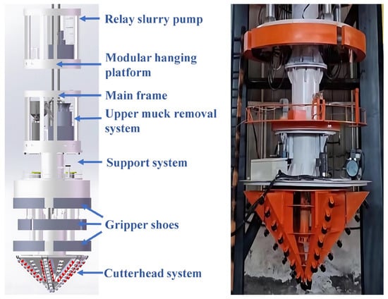
Figure 1.
Shaft boring machine (SBM) developed by the research team in the preliminary phase.
2. Materials and Methods
2.1. Rock-Breaking Model with Double Hobs on Conical Cutterhead
Rock breaking with a conical cutterhead is a process primarily driven by the collective action of a hob group. Under the thrust and torque provided by the cutterhead, the hobs rotate and penetrate into the rock. As the penetration depth increases, the rock undergoes progressive failure. A key characteristic of the conical cutterhead rock-breaking process is that parameter settings significantly affect the degree and pattern of rock damage. During the penetration of adjacent hobs, the rock develops both transverse and longitudinal cracks [16]. When these cracks interconnect between neighboring hobs, rock fragments are formed and are eventually dislodged, as illustrated in Figure 2. Therefore, the configuration of rock-breaking parameters on the cutterhead plays a critical role in determining the hob’s rock-breaking performance during excavation.
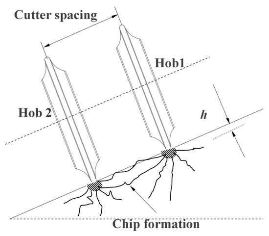
Figure 2.
Rock-shedding process.
Therefore, the rotary rock-breaking model of the conical cutterhead was established using SolidWorks 2023 to simulate the rock-breaking load and specific energy of the hob. As illustrated in Figure 3, a simplified model of the conical cutterhead and a physical image of the reaming shaft boring machine cutterhead are presented, wherein the physical image of the reaming shaft boring machine cutterhead provided a reference for the establishment of the conical cutterhead model.
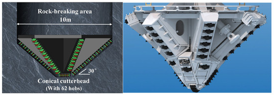
Figure 3.
Rock-breaking model of conical cutterhead and the reaming shaft boring machine cutterhead.
Considering that the double-hob rotary model can describe the damage state of rock scientifically, and it has higher calculation efficiency than the hob group, two hobs with adjacent radii above the hob group on the conical cutterhead can be selected for simulation calculation. Considering that the simulation time of one revolution is too long, this paper simplifies the rock model into a sector for simulation calculation, and its size is 1000 mm (radius) ×200 mm (height) × 400 mm (width). Because the influence area of the double-hob model on the rock is small, it will not affect the whole rock mass. Considering the calculation time and accuracy, the rock in the contact area between the hob and the rock is divided, and the rock in the rock-breaking area is divided densely. Because the outer ring of the hob is irregular, the grid in the outer ring area of the hob needs to be densified at the same time. The simplified finite element rock-breaking model of the double hobs is shown in Figure 4.
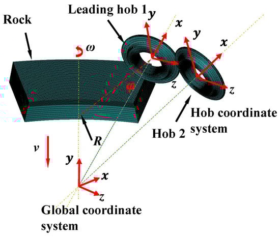
Figure 4.
Rock-breaking model with double hobs.
Reference points were established at the intersections of the axes of two adjacent hob cutters and the central axis of the rock model. These points were connected to the hobs via revolute joints to simulate the rotation of the hobs around their own axes under frictional contact with the rock. During operation, the hobs remained perpendicular to the rock surface. A downward displacement was applied to the reference points to simulate the penetration depth of the cutterhead, while a rotational angular velocity around the rock’s central axis was applied to represent the revolving speed of the shaft boring machine. Given that the stiffness of the rock is significantly lower than that of the hob material, and since this study focuses solely on the forces acting on the hobs, the hobs were simplified as rigid bodies in the dual-hob rock-breaking model. The outer surfaces of the hobs were coupled to their respective reference points. The rock was modeled using C3D8R elements with hourglass control, resulting in a total of 323,675 elements. No surrounding rock pressure was applied, and the bottom of the rock model was fully constrained. The rock-breaking surface was set at an angle of φ = 30°. In this simulation, the two hobs were configured to break rock sequentially. The influence of the phase angle between adjacent hobs on rock-breaking performance was not considered, and the angle between the two hobs was fixed at 30°.
2.2. Hob Model
The hob model employed in this study is a 17-inch (diameter D = 432 mm) disc hob with a constant cross-section [17]. The constant cross-section model of the 17-inch hob was established using SolidWorks 2019. During the rock-fragmentation process, three-directional interaction forces act between the hob ring and rock, as illustrated in Figure 5. The vertical force (FV), directed normal to the rock surface, is generated by the thrust applied from the cutterhead; the rolling force (FR), tangential to the direction of hob movement, is produced by the torque from the cutterhead; and the side force (FS) acts radially toward the center of the cutterhead.
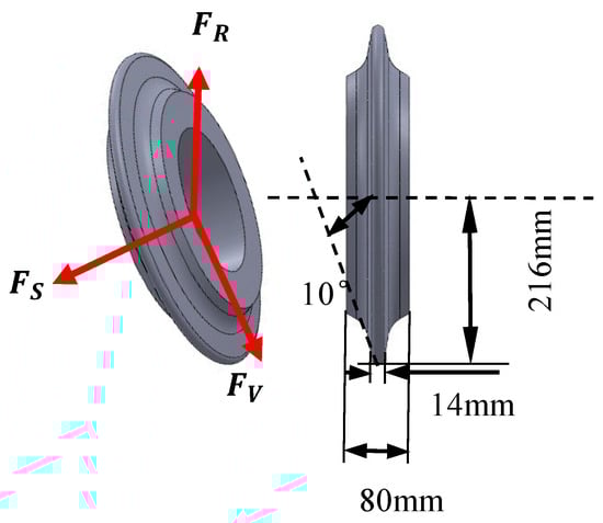
Figure 5.
Stress direction and structural parameters of the hob.
Given that this study focuses on the rock-breaking performance of the hob’s ring, and considering that the contact occurs exclusively between the cutter ring and the rock—without involving the internal state of the hob—only the cutter-ring structure was modeled in the hob’s rock-breaking simulation. The material parameters of the hob’s cutter ring are provided in Table 1.

Table 1.
Material parameters of the cutter ring.
2.3. Rock Model
During the rock-fragmentation process by the cutter, the rock at the contact surface undergoes failure and is eventually broken away. This process involves complex mechanical behaviors, including elastic–plastic deformation and failure-induced spalling of rock elements. Establishing a suitable constitutive model for the rock material is essential to accurately represent the mechanical response of rock during shaft boring machine operation, which is critical for simulating the rock-breaking process of the cutter. The Mohr–Coulomb criterion is the most commonly used yield criterion in geotechnical engineering. Its parameters (cohesion and internal friction angle) have clear physical meanings and well-established measurement methods. However, the Mohr–Coulomb criterion appears as a hexagonal pyramid in principal stress space, exhibiting singular points that can lead to convergence difficulties in the numerical solution of three-dimensional elastoplastic problems [18]. In contrast, the Drucker–Prager criterion approximates the Mohr–Coulomb yield surface with a smooth conical surface, avoiding the issue of singular points. Consequently, it demonstrates good numerical stability and computational efficiency in ABAQUS. Therefore, the constitutive model of the rock in the finite element simulation adopts the extended Drucker–Prager (D-P) model. Studies have indicated that the Drucker–Prager model implemented in ABAQUS is well-suited for analyzing rock-fragmentation processes, making it appropriate for investigating the rock-breaking mechanism of hob cutters [19]. According to the ABAQUS 2022 documentation, the Drucker–Prager (D-P) model is particularly suitable for materials whose compressive yield strength exceeds their tensile yield strength, making it appropriate for simulating the failure behavior of rocks and concrete. The implementation of the D-P model in ABAQUS extends the classical formulation by incorporating linear, hyperbolic, and exponential functions to approximate the yield surface in the meridional plane, resulting in the extended D-P model. Based on the structural and mechanical properties of granite, this study employs the extended D-P constitutive model to simulate the post-yield stress–strain relationship of the rock material. A schematic representation of the linear D-P model is provided in Figure 6. To simplify calculations and focus on the analysis of the fundamental rock-breaking mechanism of hobs, this study did not consider the influence of surrounding rock pressure and in situ stress on the rock-breaking process.
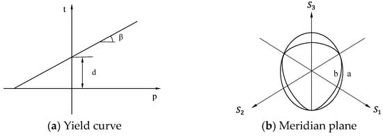
Figure 6.
Meridian plane and curve of D-P yield criterion.
The yield function and plastic potential surface function are, respectively:
When the uniaxial compressive strength of rock is given, this becomes:
When the uniaxial tensile strength t of rock is given, this becomes:
When the shear strength of rock is given, this becomes:
where F is the yield stress; t is deviatoric stress; p is equivalent stress; β is the friction angle; q is the equivalent stress of Mises; k is the ratio of triaxial tensile strength to triaxial compressive strength, and its value reflects the relationship between yield surface and principal stress (0.778 ≤ k ≤ 1); r is the ratio of the third stress invariant to the stress invariant; d is the intercept of the yield surface on the stress space t axis [20].
The rock material used in this study is granite, with its fundamental parameters summarized in Table 2. The constitutive behavior of the rock is described using the Drucker–Prager model, under the assumption that the material is isotropic, homogeneous, and exhibits continuous small-strain deformation characteristics [21].
Table 2.
Properties of rock materials.
In the process of the cutter breaking rock, there will be two failure forms of rock: in the process of direct contact between the cutter and rock, rock is squeezed and sheared by the cutter, and the stress state of the rock unit reaches its own strength limit and breaks; with the continuous increase in rock breaking depth, rock fragments fall off at this time and are in an unconstrained state. By establishing the principle of rock failure, these two states can be described [22]: the damage factor d describes the failure of rock units, and when D = 1, rock units are deleted; for rock fragments in an unconstrained state, it can be judged by the rigid body displacement U of the rock unit.
The concrete expression of the failure stripping criterion of composite rock is as follows:
where U is the displacement of the integral point of the rock element; Umax is the maximum rigid body displacement allowed by the rock element. When any one of the rock elements meets the failure criterion, the element will be deleted from the working face.
2.4. Coordinate Transformation
During the rock-breaking process, the hob interacts with the rock surface through friction and extrusion. The rock-breaking load in the global coordinate system can be obtained by extracting the support reaction force between the hob and the rock. In the simulation software, the three-directional force components can be derived individually. However, since the obtained three-dimensional forces (Fx, Fy, and Fz, where the y-axis corresponds to the rotation axis, the z-axis points inward, positive values indicate the defined direction, and negative values represent the opposite direction) are defined in the global coordinate system, they do not directly represent the actual physical forces acting on the hob. The specific expressions are as follows:
where the vertical force FV is perpendicular to the rock surface; the rolling force FR is along the hob movement direction; the lateral force FS is perpendicular to the hob movement direction and points to the center of the cutterhead; φ is the angle between the rock surface and the horizontal plane, which is 30 in this paper; ω is the angular velocity of the hob rotating around the axis; t is the time; θ0 is the angle between the hob start position and the global coordinate system; and θ is the radian of the hob current position.
Based on the sampling frequency of the simulation software, the rock-breaking load at each position of the corresponding hob in the local coordinate system was calculated. Due to the inherent fluctuation in the rock-breaking load, the average value could be biased by extreme individual data points. To mitigate this, the data after coordinate transformation were sorted, and the top and bottom 10% of values were excluded to reduce the influence of outliers. The arithmetic mean of the remaining data was then computed. This averaged load during the rock-breaking process was used as the basis for subsequent analysis.
2.5. Calculation of Specific Energy
Specific energy is one of the important indexes to reflect the rock-breaking efficiency, which represents the energy consumed in cutting rock per unit volume. The smaller the specific energy, the smaller the energy consumed in cutting rock per unit volume, and the higher the rock-breaking efficiency [23]. The calculation formula of specific energy is:
where SE is specific energy, MJ/m3; FR is the average rolling force on the cutter, kN; V is the total volume of rock crushing, m3; L is the rolling line distance of the cutter. In ABAQUS, the total volume of rock can be calculated by comparing the volume change in rock before and after rock breaking, the rolling line distance L can be calculated by the angle of cutter rolling, and the average rolling force can be calculated by the historical output.
2.6. The Orthogonal Test
The orthogonal test is a highly efficient scientific experimental method that selects a set of representative test conditions from a full-factorial experiment based on orthogonality. These selected points exhibit the characteristics of being “uniformly dispersed, balanced, and comparable.” An orthogonal array is a specially designed table, typically expressed as , where L is the code name of the orthogonal table; n is the number of tests; t is the horizontal number of each factor in the orthogonal table; c is the number of factors in the orthogonal table.
Three parameters exerting the greatest influence on cutter stress—cutter spacing, penetration depth, and cutterhead rotational speed—were selected for investigation. Each factor was tested at three levels, and a three-factor, three-level orthogonal experimental design was established, as summarized in Table 3. Here, S denotes cutter spacing (mm), P represents penetration depth (mm), and V indicates cutterhead rotational speed (r/min).
Table 3.
Parameter table of horizontal factors.
2.7. Rock-Breaking Load Model of Hob Cutters
The Colorado School of Mines (CSM) model is one of the most renowned and widely applied theoretical frameworks in the field, developed by scholars at the Colorado School of Mines. Its core concept conceptualizes the rock-fragmentation process by a hob cutter as an “indentation–fracture” mechanism: the hob penetrates into the rock under pressure, forming a crushed zone beneath the cutter. When the pressure exceeds the ultimate bearing capacity of the rock, brittle fracture occurs, resulting in the formation of rock chips along failure surfaces [24]. The Rostami model, an advancement based on the CSM model, is currently the most commonly used and highly recognized model in both engineering practice and academic research. Based on the Rostami model, a rock-breaking load model for hob cutters on a conical cutterhead is established in this study. The force analysis on the hob is illustrated in Figure 7: under the thrust of the cutterhead, rock fragmentation occurs. The total normal force acting on the hob is directed vertically downward and can be decomposed into two components: one perpendicular to the rock surface (FV) and the other parallel to the rock surface (FS).
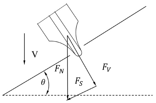
Figure 7.
Schematic diagram of force analysis on the hob.
As illustrated in Figure 8, the total normal force can be derived based on rock-fragmentation theory. Its magnitude equals the integral of the contact pressure over the contact area. The contact area between the hob and the rock can be approximated as a rectangle with a length equal to the contact chord length S, and a width equal to the hob’s edge width b.
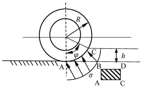
Figure 8.
Contact stress distribution during hob rock-breaking.
The contact pressure function is:
The depth of penetration into the rock is:
The chord length of the contact between the hob and the rock is:
The contact area between the hob and the rock is:
The contact angle is the angle between the contact point of the hob and the rock in the vertical direction, calculated as:
The rolling force FR can be calculated by multiplying the vertical force FV by the cutting coefficient C:
where R is the radius of the hob cutter; is the contact angle between the hob and the rock; is a correction factor related to the uniaxial compressive strength of the rock; b is the edge width of the hob; P is the penetration depth in the vertical direction; h is the depth of hob penetration into the rock; is the angle between the hob and the working plane; is the uniaxial compressive strength of the rock; C is the cutting coefficient of the hob.
3. Results and Discussion
The setting of rock-breaking parameters is crucial to the performance of hob cutters during the tunneling process. Three parameters that have the greatest impact on hob stress were selected for study. Accordingly, for the dual-hob rock-fragmentation problem, variations in cutter spacing, penetration depth, and rotational speed significantly influence rock-breaking efficiency. Based on the established rotary rock-breaking model of the dual-hob system, the rock-breaking load and specific energy under different cutter spacing, penetration depth, and rotational-speed conditions were calculated. An orthogonal experimental design was applied to analyze the variation pattern of specific rock-breaking energy under multi-factor interactions.
3.1. Influence of Penetration Depth on the Rock-Breaking Performance of the Hobs
Under the continuous thrust of the conical cutterhead, the hob cutters cause fracturing and fragmentation of the rock surface. The appropriate setting of the hob penetration depth is crucial to the rock-breaking performance of the shaft boring machine. When the penetration depth is too small, the amount of rock broken per unit time is reduced, leading to low excavation efficiency. Conversely, when the penetration depth is too large, the required thrust and torque of the cutterhead increase significantly, resulting in higher loads on the hob, reduced service life, and increased rock-breaking costs. Moreover, as the penetration depth increases while the cutter spacing remains fixed, over-crushing of the rock occurs, further reducing the efficiency of rock fragmentation. Therefore, the penetration depth not only affects rock-breaking efficiency but is also closely related to operational costs. To investigate the influence of hob penetration depth on rock-breaking performance, a simulation analysis of the rock-breaking process under different penetration depths was carried out based on the established dual-hob rotary rock-breaking model.
Under the conditions of a cutter spacing of S = 40 mm and V = 9 r/min, only the penetration depth parameter was varied. Considering that the penetration depth of hobs in practical engineering applications typically ranges from 1 to 14 mm, the penetration depth in this study was set within the interval P = 2–10 mm to evaluate the rock-breaking performance of the hob under allowable penetration conditions. On the flat cutterhead, the lateral force acting on the hob is generally negligible, as it is significantly smaller in magnitude compared to the vertical and rolling forces. In contrast, for the conical cutterhead used in this study, the average lateral force on the hob is considerably larger and acts parallel to the axis of the hob. Therefore, the influence of the lateral force on rock-breaking performance must be taken into account.
To validate the correctness of the hob rock-breaking load model established in this study, the relevant parameters were substituted into Equations (19)–(21) to calculate the normal force, lateral force, and rolling force during rock breaking. Based on numerical simulations of hob rock-breaking tests, the simulated values of the normal force and rolling force under different penetration depths were obtained. The simulation results were averaged arithmetically. As shown in Figure 9, the predicted and simulated loads of the hob under five different penetration depths are compared. It can be observed that the rock-breaking load of the hob increases with greater penetration depth. A comparison between the numerical test values and the theoretical model calculations shows minor errors in the hob’s rock-breaking load, with the curves exhibiting generally consistent trends and overall slopes. The average errors for the vertical force, lateral force, and rolling force are 3.7%, 4.3%, and 4.2%, respectively. These results demonstrate the rationality of the theoretical model for calculating hob rock-breaking forces proposed in this paper, and also verify the correctness of the numerical model for simulating rock-breaking tests.
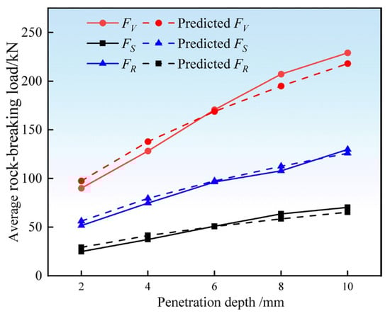
Figure 9.
Comparison of average rock-breaking loads of Hob cutters.
Xiao et al. [25] conducted full-scale linear cutting experiments on a conical cutterhead of a shaft boring machine. The rock used in their experiments was granite with a compressive strength of 102.45 MPa, while the rock in this study has a compressive strength of 97.84 MPa, and both used similar 17-inch hobs, ensuring good comparability. Due to differences between the full-scale linear cutting experiments and the rotary rock-breaking model established in this study, the rolling force and side force acting on the hob differ from the experimental loading conditions. However, the vertical force acting on the hob is consistent in direction with that in the experiments, allowing for comparison of vertical-force magnitudes to verify the accuracy of the simulation and theoretical equations. As shown in Figure 10, comparison of the vertical forces from the full-scale linear cutting experiments with the simulated and theoretically predicted values in this study reveals that both the simulated and predicted values exhibit a trend highly consistent with the experimental values—vertical force increases with penetration depth, and the numerical ranges are similar. The average error between simulation and experiment is 6%, while the average error between prediction and experiment is 10%. Therefore, the established simulation model and prediction model can be considered accurate. The above conclusions further validate the accuracy of the simulation model and theoretical prediction model presented in this paper.
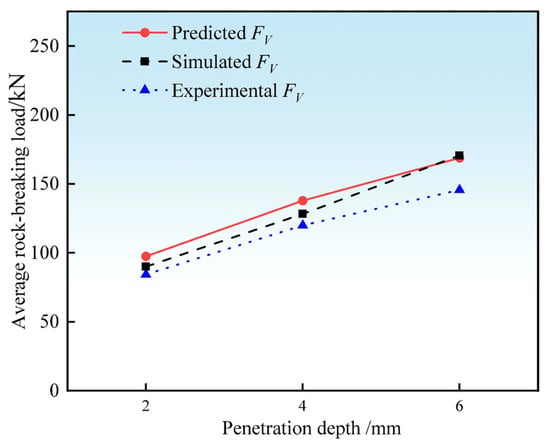
Figure 10.
Comparison of simulated, predicted, and experimental vertical forces.
The authors suggest that the discrepancies between the theoretical values derived from the hob rock-breaking force equation and the numerical simulation values may be attributed to the following reasons: the theoretical model assumes a uniform stress distribution in the contact area between the hob and the rock, while the numerical simulation accounts for contact nonlinearities and complex boundary conditions, leading to deviations between theoretical and simulated results. It is recommended that subsequent improvements to the theoretical model fully incorporate boundary condition effects. Future theoretical analyses could introduce a rock heterogeneity model to enhance the prediction accuracy of the theoretical model. Additionally, it should be noted that the current simplification neglects the friction-strengthening characteristics of the rock. Subsequent research could improve the model’s applicability by introducing correction coefficients.
As shown in Figure 11, the load on the hob exhibits significant fluctuations over time, with the amplitude of these oscillations increasing notably at greater penetration depths. This behavior is attributed to the nonlinear nature of the rock–hob interaction: when the force applied by the hob exceeds the yield strength of the rock, fracture occurs, and corresponding elements are deleted, resulting in the observed oscillatory load response. For the leading hob (Hob 1), which acts individually during initial rock cutting, the reaction force from the rock is substantially higher. As a result, both the peak load and the magnitude of fluctuations are greater for Hob 1 than for the trailing hob (Hob 2). As penetration depth increases, the lateral, vertical, and rolling forces, as well as their fluctuations, all show a noticeable increasing trend. In contrast, Hob 2 operates under cooperative rock-breaking conditions following the passage of Hob 1. Since the rock has already been pre-damaged and contains micro-cracks induced by Hob 1, the load required for Hob 2 to further fracture the rock is reduced, and its load fluctuation is comparatively smaller.
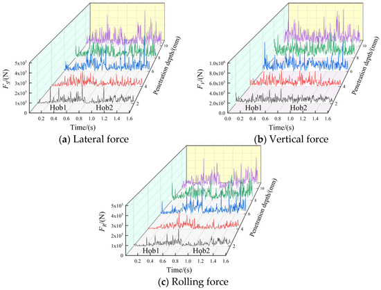
Figure 11.
Time-domain curves of rock-breaking loads for two hobs.
The specific energy of rock fragmentation under different penetration depths was calculated according to Equation (9), and the results are presented in Figure 12. This behavior can be attributed to the following mechanism: as the penetration depth gradually increases to the point where the rock ridge between adjacent hobs diminishes, the volume of rock fragmented by the hob increases, leading to a decreasing trend in the specific energy for rock fragmentation. However, when the penetration depth further increases, over-crushing of the rock occurs between the hobs. At this stage, the incremental growth in the volume of fragmented rock decreases, resulting in a higher energy consumption required to break per unit volume of rock. Consequently, the specific energy increases and the rock-breaking efficiency decreases. This observed rule is consistent with the rock-breaking behavior of hobs on flat cutterheads. When the cutter spacing is S = 40 mm, the specific energy reaches its minimum within the penetration depth range of P = 2–4 mm, indicating the highest rock-breaking efficiency under these conditions.
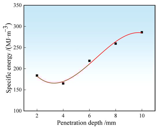
Figure 12.
Specific energy of a hob at different penetration depths.
3.2. Influence of Cutter Spacing on the Rock-Breaking Performance of the Hobs
The spacing between adjacent cutters significantly influences the rock-breaking performance, particularly that of the back hob. An excessively large cutter spacing weakens the synergistic interaction between the two hobs, leading to increased total load on the cutters and ineffective fracturing of the rock ridge formed between them. Conversely, an overly small cutter spacing causes over-crushing of the rock between the hobs, thereby reducing rock-breaking efficiency. Therefore, optimizing cutter spacing is essential for the rational design of conical cutterheads. To investigate the effect of cutter spacing on rock-breaking performance, a series of simulations was conducted using the established downward rotating dual-hob rock-breaking model under varying cutter spacing conditions.
Under the condition of P = 10 mm and V = 9 r/min for both hobs, and considering the typical hob cutter spacing range of 30–100 mm, only the cutter spacing was varied in this experiment. Simulations were performed for five different cutter spacings within the range of 40–80 mm. Given that the cutter spacing primarily influences the rock-breaking load of the back hob, only the average load of the dual-hob system was analyzed. The average rock-breaking loads are presented in Figure 13. The results indicate that the average lateral force, vertical force, and rolling force all increase with larger cutter spacing, though the rate of increase gradually decelerates. This behavior can be attributed to the fact that the leading hob induces internal damage and micro-cracking in the rock, thereby reducing the load required for the trailing hob to fracture the rock. As the cutter spacing increases, the influence of the leading hob on the trailing hob diminishes, weakening the synergistic rock-breaking effect. With a further increase in spacing, the trailing hob effectively functions as a single cutter, and the average rock-breaking load stabilizes with minimal variation.
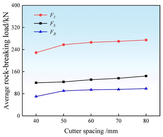
Figure 13.
Average load of the hob with different cutter spacing.
According to Equation (9), the specific energy of the hob breaking rock under different cutter spacing is calculated. The calculation result is shown in Figure 14, and the specific energy gradually increases with the increase in cutter spacing. With the increase in cutter spacing, the specific energy changes slightly. The reasons are analyzed as follows: when the cutter spacing continues to increase, the synergistic effect of adjacent hobs gradually weakens, making it difficult to form large rock blocks, while when the rolling force increases, the rock-breaking volume decreases, the rock-breaking specific energy continues to increase, and the rock-breaking efficiency decreases. When the cutter spacing continues to increase, both hobs are equivalent to single-cutter rock-breaking; the rock-breaking load and volume change little, and the rock-breaking specific energy is almost unchanged.
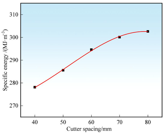
Figure 14.
Specific energy of hob with different cutter spacing.
3.3. The Influence of Cutterhead Speed on the Rock-Breaking Load of the Hobs
As the rotational speed of the cutterhead increases during the rock-breaking process, the interaction between the hob and the rock intensifies, requiring the hob to overcome greater reactive forces from the rock. Therefore, the selection of rotational speed is also crucial in studying the rock-breaking performance of the hob. To investigate the influence of cutterhead rotational speed on rock-breaking efficiency, a simulation analysis was conducted based on the established dual-hob rock-breaking model under various rotational speeds.
Under constant conditions of cutter spacing S = 40 mm and penetration depth P = 10 mm for the dual hobs, and considering that the rotational speed of the hob in practical engineering generally does not exceed 0.94 rad/s, only the rotational speed of the cutterhead was varied in this experiment. Five sets of simulations were conducted with rotational speeds ranging from 5 to 9 r/min, i.e., 0.52 to 0.94 rad/s. The computational results are shown in Figure 15. Under the condition of varying only the rotational speed, both the rolling force and vertical force increase with higher rotational speed, while the lateral force remains largely unchanged. This behavior can be attributed to the fact that, as rotational speed increases, the number of impacts per unit time between the hob and the rock rises. The superposition of impact forces leads to an increase in the rock-breaking load. Due to the heterogeneous nature of rock materials, the load experienced by the hob varies at different cutting positions. At higher rotational speeds, instantaneous load fluctuations become more frequent, resulting in more pronounced variations in amplitude and, consequently, higher rolling and vertical forces. In contrast, the lateral force, which originates from the reactive force of the rock against the side of the hob, exhibits minimal change with increasing rotational speed, as the extent of rock compression against the hob remains relatively consistent.
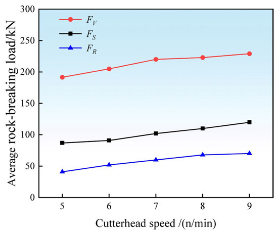
Figure 15.
Average load of double hobs at different cutterhead speeds.
According to Equation (9), the rock-breaking specific energy of the hob under different cutterhead speeds is calculated, and the calculation result is shown in Figure 16. With the increase in cutterhead speed, the rock-breaking specific energy of the hob shows a linear increase trend. The possible reason is that when the cutterhead speed is gradually increased, the movement between the hob and rock is not pure rolling, so the frequency of sliding friction between the hob and rock increases, and the average rock-breaking load of double hobs increases. Therefore, in the design stage of cutterheads of urban hard-rock shaft boring machine, the rotation speed of the cutterhead should be reasonably selected.
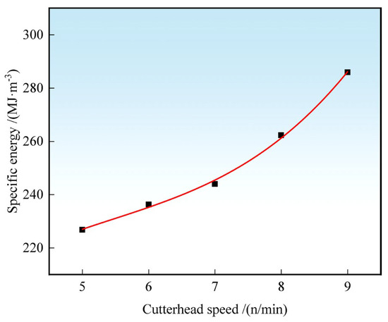
Figure 16.
Specific energy of hob with different cutterhead speeds.
3.4. Influence of Different Parameter Combinations on the Average Rock-Breaking Specific Energy of the Hobs
According to the orthogonal test method and the horizontal factor parameter table established above, the L9(33) orthogonal test table is designed, as shown in Table 3, and nine groups of simulations are carried out. The level of each group of independent variables is changed according to the test arrangement, and other conditions remain the same. The specific energy in the process of rock breaking with double hobs is selected as the test index. The orthogonal test results are shown in Table 4.
Table 4.
Orthogonal test results.
Range analysis is a data analysis method used to study the influence degree and influence law of various factors on test indicators. By comparing the cutter spacing, penetration, and the extreme difference in cutterhead speeds, the influence degree and law of each factor on the average specific energy of double hobs are determined. When the level of each factor is the same, the influence degree of each factor on the average specific energy of double hobs is completely determined by the magnitude of the extreme difference. In this orthogonal test, the level of each factor is 3, and the magnitude of the extreme difference can reflect the influence degree of each factor on the total rock-breaking load. In the table, K1j, K2j, and K3j, respectively, represent the average values of evaluation indexes corresponding to different factors at their levels, and Rj is the extreme value.
The results of the range analysis are shown in Table 5. The results are directly analyzed and compared under different conditions. The greater the range Rj, the greater the influence of this factor on the test results. From the results of the range analysis, it can be seen that the influence degree of each factor is different for different test indexes. According to the analysis results of the average specific energy of test indexes, Rj of factor P is the largest, followed by factor S, and factor V has the smallest influence; that is, the order of influence degree of each factor on average specific energy is penetration depth > cutter spacing > cutterhead speed. The smaller the specific energy of rock-breaking is, the higher the rock-breaking efficiency is. It is calculated that the best scheme in this orthogonal test is P = 2 mm, S = 60 mm, and V = 7 r/min.
Table 5.
Range analysis table.
According to the comprehensive range analysis table, the influence trend diagram of each factor level on the test index is shown in Figure 17. From Figure 17, it can be intuitively found that with the increase in penetration depth, the rock-breaking specific energy of the hob increases gradually, and the growth rate decreases gradually. With the increase in cutter spacing and cutterhead speed, the specific energy of rock breaking first decreases and then increases.
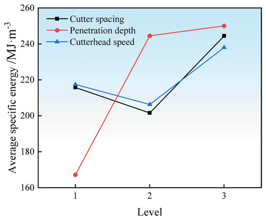
Figure 17.
Influence of cutter spacing, penetration depth, and cutterhead speed on indexes.
Analysis of variance is a data analysis method to test whether the influence of various factors on indicators is significant. Compared with the comparison of the influence degree of the range analysis method on the influencing factors, analysis of variance can quantitatively judge whether the influence of the factor on the test results is significant by comparing the single factor statistic f with the standard value of the statistic F at the specified significance level. When the factor statistic F is greater than the corresponding critical value, it indicates that the factor has a significant influence on the index.
In this paper, by calculating the F of cutter spacing, penetration depth, and cutterhead speed, it is analyzed whether each factor is significant to the average rock-breaking specific energy of double hobs under the condition of a significance level of 0.05. The calculation results are shown in Table 6. Taking the average specific energy as the index, the sum of squares of deviation SS and the degree of freedom are calculated in turn, and the F that affects each factor is obtained. It can be seen from Table 6 that, under the condition of significant level of 0.05, the influence of penetration depth on rock-breaking specific energy is significant, while the influence of cutter spacing and cutterhead rotation speed is not significant. Through variance analysis, it is determined that the primary and secondary order of each factor on rock-breaking specific energy is P > S > V, which is the same as the result of the range analysis. Based on the results of range and variance analyses, it can be concluded that penetration depth has the greatest influence on the rock-breaking specific energy of hobs.
Table 6.
Analysis of variance of rock-breaking factors.
4. Discussion
As the primary tool responsible for direct rock fragmentation during excavation, the layout and loading conditions of hob cutters significantly influence both the efficiency of rock breaking and the wear behavior and service life of the cutters during construction. The key parameters affecting the performance of urban shaft boring machines—penetration depth (P), cutterhead rotational speed (V), and cutter spacing (S)—collectively determine the machine’s excavation efficiency and advance rate. In this study, a rotary rock-breaking model of two adjacent hobs on the cutterhead was developed to simulate and analyze hob performance under various rock-breaking parameters. Using an orthogonal experimental design, range analysis and analysis of variance were applied to evaluate the influence and significance of each factor on the average specific energy of rock fragmentation. The main conclusions are as follows:
- (1)
- A theoretical model for the hob’s rock-breaking load was established based on the plastic-brittle characteristics of rock, with a verification error of less than 5%. As the penetration depth increases, the average rock-breaking load of the hob gradually increases, while the specific energy first decreases and then increases. With larger cutter spacing, the average load shows a modest increase, and the specific energy exhibits a gradually rising trend with a diminishing growth rate. As the rotational speed increases, the average load increases slightly, while the specific energy rises with an accelerating growth rate.
- (2)
- Orthogonal experiments were conducted to analyze the influence and significance of cutter spacing, penetration depth, and rotational speed on the average specific energy under multi-factor conditions. Range analysis clearly revealed the influence of each factor on specific energy, indicating that the order of significance is P > S > V. The optimal parameter combination was identified as P = 2 mm, S = 60 mm, and V = 7 r/min.
- (3)
- Analysis of variance was further employed to evaluate the significance of each factor on specific energy. The results show that, at a significance level of 0.05, penetration depth has a significant effect on specific energy, while cutter spacing and rotational speed do not exhibit a significant influence. The order of factor significance obtained from the analysis of variance (P > S > V) is consistent with the range analysis results. The above conclusions provide valuable data support for setting operational parameters and designing conical cutterhead hob layouts in urban hard-rock shaft boring machines. However, the current dual-hob rotary rock-breaking model has certain limitations. The results of this study are applicable for the comparative analysis of parameters and the understanding of underlying mechanisms, providing a theoretical reference for the design of conical cutterheads. For the quantitative prediction of on site tunneling performance, it is recommended to calibrate the model using specific rock-mechanic parameters or to introduce empirical correction coefficients. Future work will investigate the influence of multi-hob arrangement and phase angles on rock-breaking performance to further optimize the design of hob layouts on full-face conical cutterheads in urban shaft boring machines.
Author Contributions
G.L.: Writing—Review and Editing, Writing—Original Draft, Project Administration, Conceptualization. S.W.: Writing—Original Draft, Methodology, Formal Analysis, Data Curation. Y.C.: Writing—Original Draft, Visualization, Investigation. Z.Q.: Writing—Original Draft, Supervision, Resources. D.L.: Writing—Original Draft, Validation, Software. Z.D.: Writing—Review and Editing, Visualization. All authors have read and agreed to the published version of the manuscript.
Funding
The research was supported by the Henan Provincial Key Research and Development Special Project (251111220200) and the Natural Science Foundation of Henan Province Project (252300420446).
Institutional Review Board Statement
Not applicable.
Informed Consent Statement
Not applicable.
Data Availability Statement
The authors confirm that the data supporting the findings of this study are available within the article.
Acknowledgments
The authors would like to sincerely thank Henan University of Science and Technology for providing laboratory facility support and financial support. The scientific calculations in this paper were done on the HPC Cloud Platform of the Henan Collaborative Innovation Center for Advanced Manufacturing of Mechanical Equipment.
Conflicts of Interest
Authors Zhichong Qi and Dan Lyu were employed by the company China Railway Engineering Equipment Group Co., Ltd. The remaining authors declare that the research was conducted in the absence of any commercial or financial relationships that could be construed as a potential conflict of interest.
References
- Liu, Z. Analysis of key technology and research path of full section boring machine for 1000 m vertical shaft with hard rock strata. J. China Coal Soc. 2022, 47, 3163–3174. [Google Scholar] [CrossRef]
- Zhang, Z.; Cai, C.; Zhao, H. Research on cutterhead structural design of TBM. Heavy Mach. 2020, 13, 69–76. [Google Scholar] [CrossRef]
- Jin, G.; Han, B.; Liu, Z. Research onsinking technology of full-section shaft boring machine. Coal Eng. 2020, 52, 29–33. [Google Scholar]
- Zhang, Z.; Syed, N.; Wong, Z. Design and analysis of shield cutterhead structure. J. China Inst. Water Resour. Hydropower Res. 2021, 19, 342–349. [Google Scholar] [CrossRef]
- Jiang, M.; Fu, C.; Sun, R. Distinct element analysis of mechanism of rock fragmentation induced by TBM cutting in simply composite rock mass with multiple cutters. China Civ. Eng. J. 2023, 56, 1415–1436. [Google Scholar] [CrossRef][Green Version]
- Tan, Q.; Xu, Z.; Xia, Y.; Zhang, K. Numerical study on mode of breaking rock by TBM cutter in two cutting orders. J. Cent. South Univ. (Sci. Technol.) 2012, 43, 940–946. [Google Scholar]
- Huo, J.; Yang, J.; Sun, W. Simulation and optimization design of three-dimensional rotating cutting action of TBM cutter group with different modes. J. Harbin Eng. Univ. 2014, 35, 1403–1408. [Google Scholar] [CrossRef]
- Liu, J. Research on the Simulation of Cutting Rock Rotary by Hard Rock Tunnel Boring Machine Disc Cutters. J. Mech. Eng. 2015, 51, 199–205. [Google Scholar] [CrossRef]
- Zhou, P.; Guo, J.; Sun, J.; Zou, D. Theoretical Research and Simulation Analysis on the Cutter Spacing of Double Disc Cutters Breaking Rock. Ksce J. Civ. Eng. 2019, 23, 3218–3227. [Google Scholar] [CrossRef]
- Moon, T.; Oh, J. A Study of Optimal Rock-Cutting Conditions for Hard Rock TBM Using the Discrete Element Method. Rock Mech. Rock Eng. 2012, 45, 837–849. [Google Scholar] [CrossRef]
- Zhang, Y. Fragmentation characteristics of stressed rock with weak interlayers using double TBM cutters. Eng. Fract. Mech. 2025, 315, 110845. [Google Scholar] [CrossRef]
- Labra, C. Discrete/Finite Element Modelling of Rock Cutting with a TBM Disc Cutter. Rock Mech. Rock Eng. 2017, 50, 621–638. [Google Scholar] [CrossRef]
- Pan, Y.; Liu, Q.; Liu, J. Full-scale Linear Cutting Tests in Chongqing Sandstone to Study the Influence of Confining Stress on Rock Cutting Efficiency by TBM Disc Cutter. Tunn. Undergr. Space Technol. 2018, 80, 197–210. [Google Scholar] [CrossRef]
- Liu, H.; Kou, S. Numerical Simulation of the Rock Fragmentation Process Induced by Indenters. Int. J. Rock Mech. Min. Sci. 2002, 39, 491–505. [Google Scholar] [CrossRef]
- Kang, Y. Theoretical and numerical studies of rock breaking mechanism by double disc cutters. Int. J. Min. Sci. Technol. 2023, 33, 815–828. [Google Scholar] [CrossRef]
- Balci, C.; Bilgin, N. Correlative study of linear small and full-scale rock cutting tests to select mechanized excavation machines. Int. J. Rock Mech. Min. Sci. 2007, 44, 468–476. [Google Scholar] [CrossRef]
- Farrokh, E.; Rostamin, J.; Laughton, C. Study of various models for estimation of penetration rate of hard rock TBMs. Tunn. Undergr. Space Technol. Inc. Trenchless Technol. Res. 2012, 30, 110–123. [Google Scholar] [CrossRef]
- Schwartzkopff, A.K.; Sainoki, A.; Bruning, T.; Karakus, M. A conceptual three-dimensional frictional model to predict the effect of the intermediate principal stress based on the Mohr-Coulomb and Hoek-Brown failure criteria. Int. J. Rock Mech. Min. Sci. 2023, 172, 105605. [Google Scholar] [CrossRef]
- Guo, J.; Jiang, J.; Liu, X. Modification of Drucker-Prager strength criterion based on the elastic strain energy. China Civ. Eng. J. 2021, 54, 110–116. [Google Scholar] [CrossRef]
- Cho, J.W. Optimum spacing of TBM disc cutters: A numerical simulation using the three-dimensional dynamic breaking method. Tunn. Undergr. Space Technol. 2019, 25, 230–244. [Google Scholar] [CrossRef]
- Gong, Q.; Jiao, Y.; Zhao, J. Numerical modelling of the effects of joint spacing on rock fragment action by TBM cutters. Tunn. Undergr. Space Technol. 2006, 21, 46–55. [Google Scholar] [CrossRef]
- Han, M.; Cai, Z.; Qu, C. On the loads for strength design of cutterhead of full-face rock tunnel boring machine. J. Mech. Eng. 2019, 32, 99. [Google Scholar] [CrossRef]
- Rostami, J. Hard Rock TBM Cutterhead Modeling for Design and Performance Prediction. Geomech Tunnelbau 2018, 1, 18–28. [Google Scholar] [CrossRef]
- Gertsch, R.; Gertsch, L.; Rostami, J. Disc cutting tests in Colorado Red Granite: Implications for TBM performance prediction. Int. J. Rock Mech. Min. Sci. 2007, 44, 238–246. [Google Scholar] [CrossRef]
- Xiao, J.; Xia, Y.; Yang, M.; Ji, Z.; Ke, W.; Lin, L. Full-Scale Linear Cutting Experiment to Study the Rock Breaking Characteristics of the SBM Inclined-Mounted Cutter. Rock Mech. Rock Eng. 2026, 59, 617–633. [Google Scholar] [CrossRef]


Disclaimer/Publisher’s Note: The statements, opinions and data contained in all publications are solely those of the individual author(s) and contributor(s) and not of MDPI and/or the editor(s). MDPI and/or the editor(s) disclaim responsibility for any injury to people or property resulting from any ideas, methods, instructions or products referred to in the content. |
© 2026 by the authors. Licensee MDPI, Basel, Switzerland. This article is an open access article distributed under the terms and conditions of the Creative Commons Attribution (CC BY) license.