Abstract
Based on the analysis of grooves of regular and partially regular microreliefs formed on flat surfaces, the relationship between the geometric parameters of the grooves of their microreliefs, which ensures their regularity, was revealed. The functionality of the existing parameter for assessing the oil capacity of the surface of the relative area of the grooves of the microrelief was analyzed. It was proved that the parameter—the relative area of the grooves of the microrelief—is insensitive to their distribution on the plane. A new graph-analytical method for determining the planar heterogeneity of the distribution of the area of the grooves of the microreliefs was developed. A numerical parameter—the coefficient of planar heterogeneity, which determines the uniformity of the distribution of the area of the grooves on the plane, was also substantiated. The effectiveness of the new approach was demonstrated and proven. Graphs of longitudinal and transverse planar heterogeneity of the main forms of the grooves of the microreliefs were constructed, which will eliminate the need to obtain complex analytical dependencies to determine the area of these grooves. By analyzing the graphs of planar heterogeneity, numerical values of the heterogeneity coefficient were determined—a parameter that characterizes the homogeneity of microrelief grooves in the axial and interaxial directions. It is proposed to search for optimal placement schemes of adjacent microrelief grooves on the plane based on the analysis of their planar heterogeneity coefficients. This will ensure an increase in the plane heterogeneity coefficient from 0.69 to 0.97 for the triangular shape of the grooves, from 0.87 to 0.83 for the sinusoidal and from 0.46 to 0.69 for the groove shape in the form of a truncated cycloid, with the same relative areas of the microrelief.
1. Introduction
Modern mechanical engineering is focused on technologies that provide for an advanced performance of machine parts. Processing technologies and methods that ensure the improved geometrical, physical and mechanical parameters of load-bearing surfaces are being constantly improved. The technology that creates the periodically repeating self-organised surface structures commonly referred to as regular microreliefs is at the heart of surface engineering. Ensuring a periodic repetition of surface protrusions and depressions is key to a stable performance of the working surfaces of machine parts across their entire plane. When creating periodically repeating protrusions and depressions on the working surfaces of machine parts, care should be taken to provide for the microrelief’s regularity or the periodicity of microrelief’s elements, as this will ensure the surface quality [1,2].
The loss of regularity by microrelief grooves is due to a number of reasons. One of them is technological, that is, microrelief grooves are formed on machines with mechanical feed boxes. The stochastic nature and the accumulated error of such feed boxes, as well as the randomness of their feed, make the groove’s axial step constantly change by the same value. This results in the axial irregularity of the microrelief grooves.
Notwithstanding the above, partially regular and irregular microreliefs have found a broad application in modern machines. Regular microreliefs cannot be created on the end surfaces of rotary bodies. Therefore, partially regular microreliefs are created instead, as they have only one variable geometrical parameter (for example, the axial step), the rest of the geometrical parameters being identical. Owing to this, the microrelief acquires partial regularity [3,4]. As the surface approaches the center of rotation, the distance between the points of the grooves that are in the same phase decreases. Thus, it is impossible to create a completely regular microrelief on such surfaces. These articles do not specify the parameters for evaluating the unevenness of the change in the area of the grooves in the radial direction, so substantiating and recording such an evaluation parameter would allow us to show this unevenness.
Creating a hone on the inner cylindrical surface of a cylinder liner is the most common example of using irregular microreliefs. Such microrelief provides for a better performance of the sleeve surface, while its violation during operation changes the in-service properties of the surface [5,6]. The formed microrelief on the surface of the cylinder liners is not regular, but even a slight change in the angle of inclination of the grooves leads to a significant change in the operational properties of the surface. This confirms the likelihood that the uniformity of the distribution of the groove area will also have a significant impact on the operational properties of the surface. Therefore, the uniformity of the distribution of the groove area requires research to ensure stable operational properties of the surface. The confirmation that the shapes of the grooves of regular microreliefs in industry are becoming more and more diverse is the paper [7].
Optimal shapes of the regular microrelief’s grooves are described in many scientific papers. Thus, the paper presents the research findings dealing with the speed at which droplets roll down the surfaces with different microreliefs. Microrelief surfaces with nine different shapes of grooves were manufactured for this research. Surfaces with microreliefs containing longitudinal grooves were found to retain droplets longer than flat surfaces and those with other microrelief types. To evaluate various forms of grooves of complex shapes, it is necessary to develop a simple methodology that could evaluate using numerical parameters the uniformity of the distribution of the groove area and ensure stable operational properties of the surface properties. More complex groove shapes were investigated in [8]. In the paper, we describe various microrelief types created using a rotary tool. The authors developed a mathematical model that describes the tool’s motion and the microrelief profiles created depending on its service conditions. End milling was shown to be useful in creating partially regular microreliefs with different groove shapes and different mutual arrangements of the grooves. Thus, some grooves are arranged in parallel and some are offset by part of the pitch. A 2-degree-of-freedom (2-DOF) vibration platform was also developed to provide vibration along and across the feed during the micromilling process.
The importance of obtaining a parameter that will link the geometric parameters of the surface microrelief with its operational properties can be assessed by analyzing the article [9]. In this article, the authors try to find the optimal shape of the surface profile that will provide the minimum friction coefficient. For the results of the experiment to be reliable, the test specimens were designed in such a way that the relative area of the microrelief was the same. As we can see, scientists use the parameter relative area of the microrelief (Area ratio) as an important criterion that determines the operational properties of the surface. The results of the article show that although the value of the parameter relative area of the microrelief was the same for different surfaces, the friction coefficients differed significantly. However, the nature of this difference was not described. This proves once again that this parameter cannot continue to be considered as determining the operational properties of the surface, and it is necessary to search for a new, more sensitive parameter.
Surface engineering uses various forms of microrelief grooves, both discrete and continuous, which provide different in-service properties of the flat surface [10,11]. Regularity of microreliefs with discrete elements is ensured more easily, since such microreliefs have fewer geometric parameters. Based on the fact that there are different types of microreliefs, the shapes of their grooves and the connections between them, it would be advisable to investigate the relationships between the geometric parameters of the grooves, the shape of the grooves of microreliefs, with the criteria of regularity.
The relationship between surface performance and roughness parameters can be described by the Abbott-Firestone diagram. The paper in [12,13,14,15,16] describes this relationship. Here, the surface performance is evaluated by the Abbot-Firestone curve rather than the surface roughness. According to the authors, the three main parameters derived from the curve, in particular, Rpk, Rk and Rvk, may characterise the surface’s ability to resist sliding friction. The Abbott-Firestone curve is an example of a graphical–analytic analysis of microreliefs with reference to the operational properties of the surface. This method allows you to assess the properties of the surface both visually and using the numerical parameters of the Rk group. Analysis using the Abbott-Firestone curve is carried out at the microlevel. Analysis at the level of geometric dimensions of the groove has not been carried out before, since there was no corresponding method. This curve describes quite well the relationship between the surface profile at the microlevel and the wear ability. The algorithm for constructing graphs of the planar heterogeneity of microrelief grooves is similar to the algorithm for constructing the Abbott-Firestone curve and is based on the use of a set of secant segments, which, after alignment, form a plane of the curve or graph.
In the paper [17] considered surfaces with regular microreliefs and noted that they have different profile shapes. The shape and dimensions of the grooves of the microreliefs were analyzed to develop a general algorithm for their three-dimensional topographic representation based on their two-dimensional images. It was indicated that the developed algorithm works without errors when the evaluated microrelief has a high degree of regularity. The developed algorithm can be used to quickly obtain three-dimensional models of the topography of surfaces with regular microreliefs to train different types of neural networks.
In his monograph, Yu. G. Schneider [18] noted that for surfaces that perform relative movement in different directions, the optimal value of the relative area of the microrelief, which provides the most favorable friction conditions, is 28–57%. Such a large range of optimal values of this parameter indicates that the relative area of the microrelief does not provide an unambiguous assessment of the operational properties of surfaces with regular microrelief. The operational properties of surfaces with regular microreliefs and technological methods for their formation are also considered in detail in [19,20]. A significant number of experimental results summarized in these monographs confirmed the need to introduce a new, more informative parameter.
Thus, the authors of the article conducted an evaluation of surfaces with regular microreliefs, which takes into account the geometric parameters of the grooves of the microrelief. The importance of the regularity of the microrelief parameters was indicated. However, the analysis of the reasons for the loss of regularity and the phenomenon of uneven distribution of the area of these grooves on the plane was not considered. As a conclusion, it can be stated that many publications provide facts that confirm the need to develop a new approach to evaluating surfaces with regular microreliefs.
2. Regularity Parameters of a Regular Microrelief
The main goal of this article is to present a first-ever developed method for evaluating surfaces with regular and partially regular microreliefs, which takes into account the uneven distribution of the groove area over the surface plane of the samples. A numerical parameter calculated based on this method is also proposed—the coefficient of uneven distribution of the groove area.
Depending on the tools and methods used, as well as the sequence of processing operations, each mechanically treated surface has its own unique microstructure. In fact, the metal surface is a sequence of random-height protrusions and depressions, the values of which vary in a certain range. Mechanical treatment aims at a gradual levelling of the surface profile, that is, reducing the protrusions and depressions of the profile. In addition to improving the physical and mechanical properties of the surface, regular microreliefs formed on the working surfaces of machine parts also make their microstructure regular. Regular and partially regular microreliefs are designed to regularise the microrelief of machine parts’ working surfaces. In other words, they reduce the proportion of random protrusions and depressions and increase the proportion of protrusions and depressions that have an ordered microstructure. This ensures the stability of the geometrical, physical and mechanical properties of machine parts’ working surfaces.
The main geometrical parameters of microrelief grooves are the amplitude Ag, axial step Tg, interaxial distance So and groove width bg. The axial line’s shape of a continuous regular micro-roughness is also important. The axial line may have different shapes. For regular microreliefs, a sinusoidal shape or a periodically repeating triangular shape of the axial line is most common.
Different microrelief types have different numbers of regularity criteria. The regularity of microrelief grooves appears a bigger problem than it might seem.
Axial (pitch) regularity is the repeatability of the microrelief elements’ shapes (grooves, holes, etc.) in the axial direction with a pitch Tg.
Interaxial regularity is the repeatability of the microrelief elements’ shapes (grooves, holes, etc.) in the interaxial direction with a periodicity So.
The regularity of discrete elements shown in Figure 1b takes into account the elements’ shape, that is, holes with a diameter D; however, it does not take into account the amplitude, a parameter characteristic of elements with solid grooves.
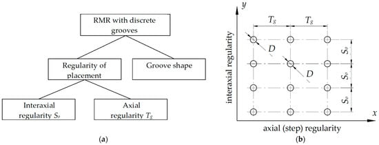
Figure 1.
Regularity parameters of a regular microrelief with discrete elements: (a) a scheme for ensuring regularity; (b) graphical display of parameters.
Thus, to provide for a complete regularity of regular microreliefs with discrete elements, we need to ensure the regularity of the microrelief elements’ shape and the regularity of their planar arrangement. In other words, the interaxial and axial (pitch) distances should be the same (Figure 1a).
As seen from Figure 1b, the regularity of this microrelief type requires the periodicity of repetition of only three parameters: the axial step Tg, the interaxial distance So and the microrelief element’s shape. The microrelief element’s shape is ensured by the stability of the conditions under which it is formed. When microrelief is formed mechanically, the element’s shape is ensured by the stability of the deformation force.
To provide for the regularity of microreliefs with continuous rectilinear grooves (Figure 1), we need to ensure both the regular arrangement of the microrelief grooves on the plane and the identical shape of the microrelief grooves.
Figure 2 shows the relationship between the geometrical parameters that ensure the regularity of microreliefs with continuous grooves. In the axial direction, regularity is provided by the groove’s shape, which includes such parameters as the axial step Tg, the amplitude Ag and the groove’s width bg. In the interaxial direction, the regularity of the microrelief with solid grooves is ensured by the uniformity of interaxial step So.
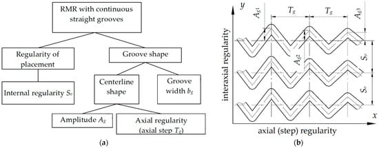
Figure 2.
Regularity parameters of a regular microrelief with continuous elements: (a) a scheme for ensuring regularity; (b) graphical display of parameters.
Partially regular microreliefs are characterised by the grooves that have one or several variable geometrical parameters, with the other geometrical parameters being identical. The identical geometrical parameter retains regularity. However, the unstable values, that is, the ones that vary, must have a repetition frequency which is usually equal to the microrelief groove’s pitch. Thus, partially regular microrelief’s grooves formed on the end surfaces of rotary bodies (Figure 3b) have the same amplitude Ag1 = Ag2. However, as the distance to the rotation center of the rotary body’s end surface increases, the axial step of the grooves increases Tg2 > Tg1. At the same time, if we represent the axial step in the polar coordinate system using angle φ, this parameter will be stable for the grooves located at any distance from the rotation center of the rotary body’s end surface.
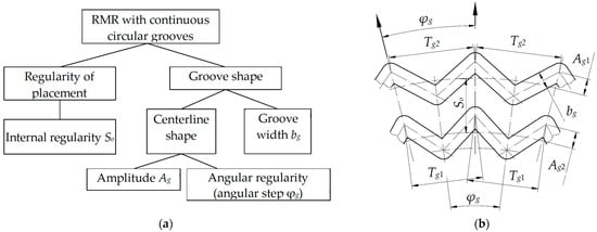
Figure 3.
Regularity parameters of a partially regular microrelief with continuous elements: (a) a scheme for ensuring regularity; (b) graphical display of parameters.
Figure 3 shows the regularity parameters of a partially regular microrelief with continuous circular grooves (elements) formed on a flat surface of a rotary body. Interaxial distance So between microrelief grooves is the same, which ensures microrelief’s regularity in the interaxial direction. The axial step Tg for the grooves, the centerlines of which are located at different distances from the center of rotation, will be different, that is, Tg1 ≠ Tg2 (Figure 3b). The concept of the groove’s angular pitch φg is introduced, which is the same for all the grooves, the centerline of which is located at different distances from the center of rotation.
Thus, the microrelief’s regularity preserves the law that describes changes in the argument of the continuous regular micro-roughness’ axial line, in which the step and amplitude of the microrelief’s groove remain constant, as well as the arrangement of the upper and lower equidistance relative to this line on the plane where the regular microrelief is formed. This parameter is ensured by a stable groove’s width.
The stages of microrelief grooves’ regularity can be depicted graphically using the diagram shown in Figure 4. An irregular microrelief results from the mechanical processing of surfaces and is characterised by the variability of parameters that account for the groove’s geometrical shape (amplitude Ag, step Tg, groove width bg) and the parameters that account for the arrangement of microrelief grooves on the plane (interaxial step So).
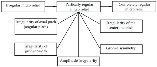
Figure 4.
Stages of microrelief’s regularity and irregularity criteria.
A complete regularity of microrelief grooves can be ensured if all of the above parameters are stable. The resulting microrelief will have grooves that touch (microrelief types IV and V according to [21]).
The largest group is represented by partially regular microreliefs. The presence of at least one feature shown in Figure 4, or their combination, allows classifying the microrelief as partially regular. A microrelief cannot be considered partially regular if its grooves are not similar in shape.
Microreliefs created by the rotational method can also be partially regular. They form an axial line of continuous regular micro-roughness in the form of a cycloid. The corresponding elements of the microrelief groove (protrusions, depressions, arcs, etc.) must repeat with an axial step Tg. Owing to this, the regularity of microrelief groove’s parameters will be ensured (Figure 5b). So, the microreliefs shown in Figure 5 have completely repetitive elements with a period Tg. However, the microrelief shown in Figure 5a is symmetrical with respect to the a-a and b-b axes, and the microrelief shown in Figure 5b is symmetrical only with respect to the b-b axis. Grooves of this shape will never add a complete regularity to a microrelief.

Figure 5.
Symmetry of microrelief grooves: (a) triangular profile (b) circular profile.
The numerical value of the groove’s area used to estimate the relative microrelief’s area allows evaluating the ratio of the microrelief’s area to the surface’s area on which it is formed. However, this parameter does not evaluate the arrangement of grooves on the plane, which is almost always non-uniform. That is why it is advisable to introduce a microrelief evaluation parameter that will depict the uniformity of the microrelief grooves’ arrangement, namely, the distribution of their area on the plane. This can be done using a graph that shows the groove area’s distribution in different planar directions.
To evaluate the uniformity of the grooves’ arrangement on a plane, we introduce an indicator of the planar non-uniformity of the microrelief grooves’ shapes. The following method is proposed for plotting planar non-uniformity graphs.
3. Planar Non-Uniformity of Microrelief Grooves’ Shapes
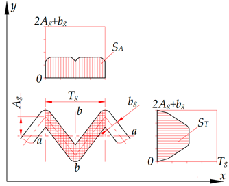
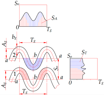
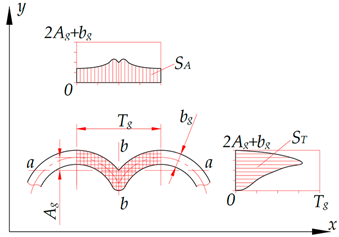
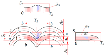
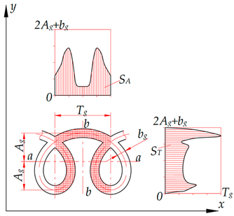
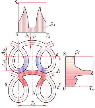
Planar non-uniformity of microrelief grooves’ shapes is a parameter that characterises the uniformity of the groove’s area’s distribution on a plane limited by axial step Tg in the axial (longitudinal) direction and by the value 2Ag + bg in the interaxial (transverse) direction (Figure 6). The planar non-uniformity is determined by the graph showing the groove’s area’s distribution within the axial step Tg in the longitudinal direction and within value 2Ag + bg in the transverse direction. Surface areas under the curve on the planar non-uniformity graphs are identical in the axial SA and interaxial ST directions. This parameter makes it possible to evaluate the microrelief’s relative area, which is one of the main parameters characterising the performance of surfaces with regular and partially regular microreliefs.
where Fn—relative surface area with regular microrelief, %;
SA—surface area under the curve of plane inhomogeneity of the groove in the axial direction, mm2;
Tg—axial pitch of the groove, mm;
Ag—groove amplitude, mm.
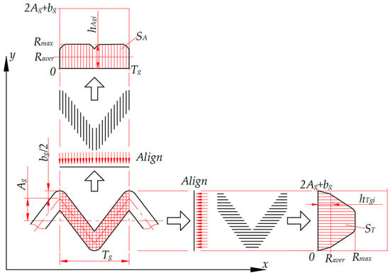
Figure 6.
Scheme for plotting the axial and interaxial planar non-uniformity of the microrelief grooves’ shapes.
A graphical-analytical method for determining the relative area of surfaces with regular microreliefs is proposed. The method determines the surface area occupied by a groove element as a set of segments parallel to one of the groove’s axes. These segments intersect the axe’s body and are aligned along the axis to which they are perpendicular (Figure 6). This method also determines the area of complex-shaped microrelief grooves and their intersections. It eliminates the need in deriving complex analytical dependencies and is quite simple to apply, especially using modern programs for processing graphic information.
The surface area formed this way can easily be determined using the graphics software, for instance, AutoCAD 2020. Thus, when determining the relative area of the microrelief, this method eliminates the need in deriving complex analytical relationships to determine the area of the grooves arranged on the surface plane.
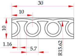
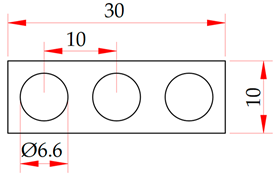
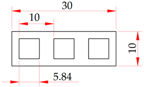
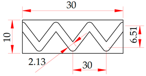
To confirm the effectiveness of the proposed method, it is proposed to compare the results of evaluating microreliefs with different shapes of elements/grooves formed on a plane of the same size according to the parameters “relative area of microrelief” and “coefficient of planar heterogeneity” and summarized in Table 1. The physical meaning of the coefficient of planar heterogeneity kg is that it shows the ratio between the average value of the groove cross-section and its maximum value on the graph of planar heterogeneity (Figure 6). Its value will increase if the lengths of the groove sections are the same; for example, if the groove has the shape of a rectangle, and vice versa, it will decrease if the lengths of the groove sections differ significantly.

Table 1.
Results of evaluation of microreliefs with different shapes of elements/grooves according to the parameters “relative area of microrelief” and “coefficient of planar heterogeneity”.
As can be seen from Table 1, the relative area of the microrelief Fn determined by Formula (1) for all samples is the same and is 34.1%. The coefficient of planar heterogeneity kg, which is determined for the same samples in the horizontal direction, has a value from 0.49 to 1.0. The maximum value of the coefficient of planar heterogeneity in a groove, in which its area is distributed absolutely evenly along the surface (the shape of the groove is a rectangle), is calculated.
Thus, the proposed numerical parameter of the estimate provides sensitivity to the uniformity of the distribution of the groove area in the selected direction, which cannot be provided by the coefficient of the relative area of the microrelief.
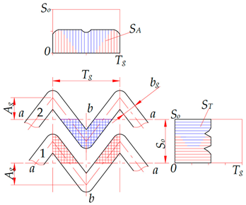
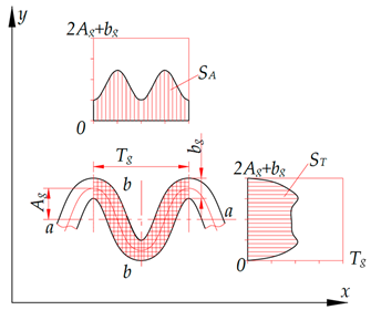
The axial direction is located along the groove’s axis. It coincides with the x axis of the coordinate system. The interaxial direction coincides with the y axis. The symmetry of the microrelief grooves’ planar non-uniformity graph for the triangular and sinusoidal grooves (Table 2) indicates their regularity in the axial direction relative to the b-b axis and in the interaxial direction relative to the a-a axis. In addition, the analysis of the planar non-uniformity graphs for triangular grooves suggests that the distribution of the SA groove’s area along the x axis is more uniform than that of the ST groove’s area along the y axis. In this case, the numerical value of the areas occupied by separately studied grooves is always the same, that is, SA = ST. However, when plotting the planar non-uniformity graphs for several adjacent grooves, their areas will overlap and will not be the same, that is, SA ≠ ST.

Table 2.
Graphs of longitudinal and transverse planar non-uniformity of groove shapes of microreliefs formed on flat surfaces.
In the axial direction, the planar non-uniformity of adjacent grooves is determined at a distance equal to the grooves’ axial step Tg. In the interaxial direction, it is determined at a distance equal to the interaxial distance So. In case of individual grooves, it is defined at a distance of 2Ag + bg. This is because the grooves’ shape is repeated periodically. If the interaxial distance between the grooves is less than or equal to 2Ag + bg, the adjacent grooves will affect the value of the determined area by increasing it.
When analysing the planar non-uniformity graphs for the grooves in the form of the truncated and elongated cycloid (Table 2), we observe a clearly pronounced planar non-uniformity in the axial and interaxial directions in the form of peak protrusions. These protrusions indicate that the groove’s surface area is significantly larger at certain locations along one of the axes. A non-uniform distribution of the groove’s area over the surface accounts for the different geometrical, physical and mechanical parameters of the surface and, accordingly, affects its performance [18,21,22,23].
The non-uniformity of the groove’s surface area distribution should be determined by the uniformity coefficient kg, a numerical parameter defined as the ratio of the maximum groove’s height Rmax to its average height Raver.
The value of this coefficient is determined either in the axial or interaxial direction. Under a completely uniform distribution of the groove’s area, the coefficient will be equal to 1. The level of approximation to this value reflects the degree of uniformity of the groove’s area distribution in the selected direction.
where hAgi (hTgi) is the height of the i-th segment on the corresponding planar non-uniformity graph, mm (Figure 6).
Height values hAgi are defined within the axial step Tg for the axial planar non-uniformity graphs, while height values hTgi are defined within the interaxial step So for the interaxial planar non-uniformity graphs.
The analysis of the planar non-uniformity graphs of the microrelief grooves’ shape allowed us to arrange the adjacent microrelief grooves in such a way (Table 2) that the distribution of their areas became more uniform. This is confirmed by the axial and interaxial coefficients of planar non-uniformity kg.
Table 3 and Table 4 indicate that the planar non-uniformity coefficient can be increased in the axial and interaxial directions by optimising the arrangement of microrelief grooves. Owing to this, the groove’s area will be more uniformly distributed along the plane on which the microrelief is formed. The tables also indicate that the rotational microrelief grooves, which have an asymmetric shape relative to the longitudinal axis, are hard to arrange in a better way.

Table 3.
Planar non-uniformity coefficients kg of microrelief grooves.

Table 4.
Planar non-uniformity coefficient kg after adjusting the position of microrelief grooves based on the analysis of the planar non-uniformity graphs.
Using the results of the proposed method will allow creating surfaces with regular microreliefs, the surface area of the grooves of which will be evenly distributed in the required directions. The uniformity of the distribution of the area of the grooves will ensure the same operational properties of the surface [21]. The friction coefficient will decrease due to the uniformity of the distribution of contact stresses in the friction pair. This, in turn, will increase the resistance of the surface to seizing of the second kind.
The proposed method and the coefficient calculated on its basis can be used for comparative analysis of surfaces with regular microreliefs, Table 5.

Table 5.
Comparative characteristics of the application of the coefficient of planar uniformity, kg and the relative area of microrelief, Fn.
Thus, it can be stated that the method of assessing the planar uniformity of grooves of regular and partially regular microreliefs proposed by the authors in this article and the numerical parameter calculated on its basis allow the following advantages to be provided (Table 5).
- -
- reduction in the surface ability to the onset of conditions for the onset of the second-order setting process, since the reduction in contact interaction locations [18];
- -
- uniform distribution of lubricant over the surface, since the grooves of the microrelief accumulate it when in contact with the lubricant [19,20];
- -
- uniform distribution of contact interaction locations of two surfaces of the friction pair, since the surfaces contact evenly spaced locations formed by the grooves of the microrelief [4,14].
4. Conclusions
The main shapes and geometric features of grooves of regular and partially regular microreliefs formed on flat surfaces have been analyzed. Schemes of the relationship between the geometric parameters of grooves of microreliefs, which ensure their regularity, have been constructed, and the criteria for their regularity have been established.
It has been established that the existing parameter for assessing the influence of the groove area—the relative area of the microrelief—is insensitive to the distribution of this area on the plane. A new graph-analytical method for determining the planar heterogeneity of the distribution of the area of grooves of microreliefs has been proposed for the first time. A numerical parameter—the coefficient of planar heterogeneity, which determines the uniformity of the distribution of the area of grooves on the plane, has also been proposed. Graphs of the longitudinal and transverse planar heterogeneity of the main forms of grooves of microreliefs have been constructed, which will eliminate the need to obtain complex analytical dependencies to determine the area of these grooves.
Analysis of the plane heterogeneity graphs allows us to determine the numerical values of the heterogeneity coefficient—a parameter that characterizes the homogeneity of the microrelief grooves in the axial and interaxial directions. It is recommended to search for the optimal layout of adjacent microrelief grooves on the plane based on the analysis of their plane heterogeneity coefficients, which allows us to increase the plane heterogeneity coefficient from 0.69 to 0.97 for the triangular shape of the grooves, from 0.87 to 0.83 for the sinusoidal shape, and from 0.46 to 0.69 for the shape of the groove in the form of a truncated cycloid.
Author Contributions
Investigation, V.D. and P.M.; writing—original draft, R.B. and I.Z.; writing—review and editing, V.D., P.M., R.B. and I.Z.; visualization, V.D.; supervision, V.D. and P.M. All authors have read and agreed to the published version of the manuscript.
Funding
This research received no external funding.
Institutional Review Board Statement
Not applicable.
Informed Consent Statement
Not applicable.
Data Availability Statement
Data are contained within the article.
Conflicts of Interest
The authors declare no conflicts of interest.
References
- ISO 21920-2:2022; Geometrical Product Specifications (GPS)—Surface Texture: Profile—Part 2: Terms, Definitions and Surface Texture Parameters. ISO: Geneva, Switzerland, 2022. Available online: https://www.iso.org/standard/72226.html (accessed on 16 April 2023).
- ISO 25178-2:2021; Geometrical Product Specifications (GPS)—Surface Texture: Areal—Part 2: Terms, Definitions and Surface Texture Parameters. ISO: Geneva, Switzerland, 2021. Available online: https://www.iso.org/standard/74591.html (accessed on 16 April 2023).
- Chen, S.; Yang, S.; Liao, Z.; Cheung, C.F.; Jiang, Z.; Zhang, F. Study of deterministic surface micro-texture generation in ultra-precision grinding considering wheel oscillation. Opt. Express 2022, 30, 5329–5346. [Google Scholar] [CrossRef] [PubMed]
- Dzyura, V.; Maruschak, P.; Slavov, S.; Dimitrov, D.; Semehen, V.; Markov, O. Evaluating Some Functional Properties of Surfaces with Partially Regular Microreliefs Formed by Ball-Burnishing. Machines 2023, 11, 633. [Google Scholar] [CrossRef]
- Mezghani, S.; Demirci, I.; Zahouani, H.; El Mansori, M. The effect of groove texture patterns on piston-ring pack friction. Precis. Eng. 2012, 36, 210–217. [Google Scholar] [CrossRef]
- Pawlus, P.; Koszela, W.; Reizer, R. Surface Texturing of Cylinder Liners: A Review. Materials 2022, 15, 8629. [Google Scholar] [CrossRef] [PubMed]
- Zhao, M.; Li, W.; Wu, Y.; Zhao, X.; Tan, M.; Xing, J. Performance Investigation on Different Designs of Superhydrophobic Surface Texture for Composite Insulator. Materials 2019, 12, 1164. [Google Scholar] [CrossRef] [PubMed]
- Song, B.; Zhang, D.; Jing, X.; Ren, Y.; Chen, Y.; Li, H. Theoretical and Experimental Investigation of Surface Textures in Vibration-Assisted Micro Milling. Micromachines 2024, 15, 139. [Google Scholar] [CrossRef] [PubMed]
- Zhan, X.; Yi, P.; Liu, Y.; Xiao, P.; Zhu, X.; Ma, J. Effects of single- and multi-shape laser-textured surfaces on tribological properties under dry friction. Proc. Inst. Mech. Eng. Part C 2019, 234, 1382–1392. [Google Scholar] [CrossRef]
- Wang, J.; Xue, W.; Gao, S.; Li, S.; Duan, D. Effect of groove surface texture on the fretting wear of Ti–6Al–4V alloy. Wear 2021, 486–487, 204079. [Google Scholar] [CrossRef]
- Ge, Z.; Hu, Q.; Wang, R.; Fei, H.; Zhu, Y.; Wang, Z. Machine Learning-Driven Optimization of Micro-Textured Surfaces for Enhanced Tribological Performance: A Comparative Analysis of Predictive Models. Coatings 2024, 14, 1539. [Google Scholar] [CrossRef]
- Amine, H. Effect of cutting variables on bearing area curve parameters (BAC-P) during hard turning process. Arch. Mech. Eng. 2020, 67, 73–95. [Google Scholar] [CrossRef]
- Milton, C.-S.; Irene, C.; Guillermo, V. Characterization of surface topography with Abbott Firestone curve. Contemp. Eng. Sci. 2018, 11, 3397–3407. [Google Scholar] [CrossRef]
- Pawlus, P.; Reizer, R.; Wieczorowski, M.; Krolczyk, G. Material ratio curve as information on the state of surface topography—A review. Precis. Eng. 2020, 65, 240–258. [Google Scholar] [CrossRef]
- Kubatova, D.; Melichar, M. Roughness Evaluation Using Abbott-Firestone Curve Parameters. In Proceedings of the 30th DAAAM International Symposium, Vienna, Austria, 20–27 October 2019; pp. 0467–0475. [Google Scholar] [CrossRef]
- Raynald, L.; Philippe, D.; Nathalie, D.; Olivier, C.; Jérôme, N. Subsurface damage distribution characterization of ground surfaces using Abbott–Firestone curves. Opt. Express 2012, 20, 13551–13559. [Google Scholar] [CrossRef] [PubMed]
- Slavov, S.; Van, L.S.B.; Dimitrov, D.; Nikolov, B. An Approach for 3D Modeling of the Regular Relief Surface Topography Formed by a Ball Burnishing Process Using 2D Images and Measured Profilograms. Sensors 2023, 23, 5801. [Google Scholar] [CrossRef] [PubMed]
- Scheider, Y.G. Service Properties of Parts with Regular Microrelief, 2nd ed.; revised and augmented; Mashinostroenie: Leningrad, Russia, 1982; 248p. (In Russian) [Google Scholar]
- Dzyura, V.O.; Maruschak, P.O. Technological Methods for Ensuring the Quality Parameters of Surfaces of Bodies of Revolution and Their Profilometric Control; Palanytsia, V.A.: Ternopil, Ukraine, 2021; 170p. (In Ukrainian) [Google Scholar]
- Dzyura, V.O.; Maruschak, P.O. Features of the Formation of Partially Regular Microreliefs on the End Surfaces of Parts of the “Body of Revolution” Type; Palanytsia, V.A.: Ternopil, Ukraine, 2022; 162p. (In Ukrainian) [Google Scholar]
- Grochała, D.; Grzejda, R.; Józwik, J.; Siemiatkowski, Z. Improving the Degree of Surface Isotropy of Parts Manufactured Using Hybrid Machining Processes. Coatings 2025, 15, 461. [Google Scholar] [CrossRef]
- Dzyura, V.; Maruschak, P.; Bytsa, R.; Zinchenko, I. Partially Regular Microreliefs Formed by Rotation. Constr. Mater. 2025, 5, 2. [Google Scholar] [CrossRef]
- Dzyura, V.; Maruschak, P.; Slavov, S.; Dimitrov, D. Applying regular relief onto conical surfaces of continuously variable transmission to enhance its wear resistance. Transport 2023, 38, 178–189. [Google Scholar] [CrossRef]
Disclaimer/Publisher’s Note: The statements, opinions and data contained in all publications are solely those of the individual author(s) and contributor(s) and not of MDPI and/or the editor(s). MDPI and/or the editor(s) disclaim responsibility for any injury to people or property resulting from any ideas, methods, instructions or products referred to in the content. |
© 2025 by the authors. Licensee MDPI, Basel, Switzerland. This article is an open access article distributed under the terms and conditions of the Creative Commons Attribution (CC BY) license (https://creativecommons.org/licenses/by/4.0/).
