Article

Enhancing Dry-Sliding Wear Performance of a Powder-Metallurgy-Processed “Metal Matrix–Carbide” Composite via Laser Surface Modification

1
Institute of Materials Research, Slovak Academy of Sciences, 04001 Kosice, Slovakia
2
Physics Department, Pryazovskyi State Technical University, 49044 Dnipro, Ukraine
3
Department of Materials Science and Engineering, Lviv Polytechnic National University, 79000 Lviv, Ukraine
*
Author to whom correspondence should be addressed.
Eng 2025, 6(11), 313; https://doi.org/10.3390/eng6110313
Submission received: 29 September 2025 / Revised: 3 November 2025 / Accepted: 3 November 2025 / Published: 5 November 2025
(This article belongs to the Special Issue Advances in Precision Machining and Surface Engineering of Materials)

Abstract

The increasing demand for enhanced wear resistance and mechanical integrity in tooling applications has driven the development of advanced surface engineering strategies for high-alloy steels. Böhler K390 MICROCLEAN, a powder-metallurgical V–Cr–Mo–W cold work tool steel with high vanadium content, features a composite metal matrix–carbide microstructure, consisting of uniformly distributed coarse vanadium carbides and finer carbides (M7C3, M6C/MC) embedded in a ferritic matrix. This study investigated the effects of non-melting laser surface treatment (LST) applied to both as-received and bulk heat-treated K390 specimens. Microstructural characterization using SEM, EBSD, XRD, and EDX revealed the formation of a hardened surface layer comprising a structureless mixture of ultrafine-grained martensite and retained austenite, localized around vanadium carbides. Lattice parameter analysis and Williamson–Hall evaluation demonstrated increased carbon content, lattice distortion, and crystallite size reduction, contributing to high dislocation density (6.4 × 10¹⁴ to 2.6 × 10¹⁵ m−2) and enhanced hardness. Microhardness was increased by up to 160% compared to the initial state (reaching 835–887 HV20), and dry-sliding testing showed up to 3.94 times reduced volume loss and decreased friction coefficients. Wear occurred via the formation and delamination of thin oxide tribo-layers, which enhanced the wear behavior. The combined approach of bulk heat treatment followed by LST produced a graded microstructure with superior mechanical stability, offering clear advantages for extending tool life under severe contact loads in stamping and forming operations.

1. Introduction

Increasing requirements for improved durability and performance in tool steels for high-wear industrial environments have driven significant progress in surface engineering, employing innovative approaches to enhance high-alloyed tool steels such as K390, AISI D2, AISI O1, and H13. These steels remain critical for applications that require exceptional hardness, wear resistance, and toughness, including cutting tools, dies, and moulds for metal forming and plastics processing. Böhler K390 MicroClean (hereafter K390), a powder metallurgy (PM) process V–Cr–Mo–W–Co cold work tool steel, is notable for its high vanadium content (9 wt.%), which ensures advanced wear resistance [1]. K390 exhibits a metal matrix–carbide composite microstructure formed through the PM process [2,3] enabling uniform distribution of its dissimilar powder constituents. The microstructure of K390 comprises grainy carbides evenly dispersed within a metallic (Fe-BCC) matrix, providing a clear advantage in the toughness–wear resistance balance compared to the analogous cast or wrought tools steels [4,5]. K390 exhibits exceptional operational durability, primarily due to the presence of hard globular vanadium carbides within its microstructure [6,7,8].
According to the conventional technological route, cold work tool steels are subjected to multistep heat treatment combining high-temperature austenitization, quenching, and repeated tempering, which enables the transformation of the matrix from ferrite to martensite, achieving a hardness of up to 64 HRC [1]. Bulk cryotreatment is able to further improve wear resistance by transforming retained austenite (RA) into martensite, as demonstrated by Surekha and Els-Botes for PM K390 and wrought AISI H13 steel [9]. However, the need for extended tool life and durability under extreme wear conditions has continued to motivate research into advanced surface modification techniques (coating deposition [10,11], thermochemical pack treatment [12], glow-discharge plasma nitriding [8], ultrasonic impact treatment [13], pulsed-plasma coating deposition [14], severe plastic deformation [15], etc). Among these techniques, laser surface treatment (LST) stands out as a precise, non-contact method to enhance surface properties through phase transformations, which improve hardness, wear resistance, and fatigue strength while maintaining the bulk properties of the material [16,17]. LST has been reported to improve the performance of tool steels [18,19] and structural steels [20,21,22]. Non-melting laser surface treatment employed rapid heating and cooling cycles induced by a laser beam to drive phase transformations, such as the formation of fine-grained martensite, without melting the surface [23]. This approach minimised thermal distortion and defects like cracks or porosity, which are common in melt-based processes such as laser cladding or welding [24]. The localised energy input enabled precise control over the heat-affected zone (HAZ), producing a functionally graded, complex microstructure resistant to surface cracking. For instance, Telasang et al. [25] demonstrated that laser surface hardening of AISI H13 tool steel significantly enhanced hardness and wear resistance by forming a martensitic surface layer with minimal impact on the substrate’s toughness. Similarly, El-Batahgy [26] reported improved wear and corrosion resistance in laser-hardened tool steels, highlighting the potential of laser processing for tailoring surface properties for specific applications. Additionally, laser treatment (including laser shock processing [27,28]) introduced compressive residual stresses, enhancing fatigue resistance, thermal-crack resistance, and durability in high-wear environments, as demonstrated in studies on laser-hardened AISI D2 tool steel [28] and P20 structural steel [29]. The use of laser beams for surface polishing of tool die steels has been reported elsewhere [30,31,32].
The primary objective of laser surface treatment on tool steels was to enhance surface hardness and wear resistance through phase transformations, such as the conversion of austenite to martensite or the refinement of carbide structures [33]. Studies on laser hardening of structural steels, such as 4340 and En24 [34,35,36], showed that rapid cooling rates (often exceeding 103 °C/s) promoted the formation of a hardened martensitic layer, significantly improving wear performance. The unique microstructure of powder metallurgical tool steels like K390 [37], characterised by fine, evenly distributed vanadium carbides, presented both opportunities and challenges for laser surface treatment. However, the high alloying element content in K390 was found to alter phase transformation kinetics, potentially leading to microstructural behaviour that differs from conventionally produced tool steels like AISI M2 and D2 [38]. The presence of highly alloyed carbides and their thermal stability was shown to amplify these effects, as demonstrated by Mahmoudi et al. [39], who investigated laser hardening of AISI 420 steel. Therefore, LST of powder metallurgy composites like K390 required the careful optimization of laser parameters—pulse duration, energy density, and scanning speed—to achieve the desired phase transformations without causing carbide coarsening or surface cracking.
The tribological benefits of laser surface treatment were critical for tools used in abrasive or adhesive wear conditions, such as cutting or forming applications [40]. Yang et al. [41] investigated laser surface texturing of tool steels, including AISI D2, and reported that controlled laser processing enhanced tribological performance, reduced friction, increased anti-adhesive properties, and improved wettability and lubrication applications. Conversely, Moravčíková et al. [42] observed that laser texturing did not influence the tribological performance of K390. When LST proceeded through surface melting, the microstructure changed significantly from PM uniform carbide distribution to a fine cellular-dendritic structure resulting from carbide eutectic crystallization, accompanied by an increase in RA volume fraction [43,44]. Thus, LST of carbide-matrix alloys often exhibited a tendency for crack formation due to thermal stresses [45]. The authors of [46] recommended pre-heating to 350 °C to prevent cracking in K390 during laser treatment involving surface melting. Surface laser melting of Cr-containing tool steels has been shown to improve their corrosion resistance [44,47].
Despite these advances, several unresolved challenges have remained in the laser surface treatment of high-alloyed tool steels, particularly powder-metallurgical grades like K390. The complex interplay between laser parameters, phase transformation kinetics, and the role of high vanadium content in controlling carbide stability and surface integrity has not been fully understood. Currently, limited information exists regarding laser processing of K390 steel in a non-melting mode and its impact on microstructural evolution and tribological performance, given its composite nature. The present study aims to addresses these challenges by investigating the laser surface treatment of Böhler MicroClean K390 without melting, aiming to elucidate the mechanisms governing phase transformations and their impact on hardness and wear resistance. By exploring the relationships between microstructural evolution and tribological performance, this work seeks to advance the understanding of laser processing for powder-metallurgical produced tool steels with the goal of optimising surface treatment approaches and contributing to improved tool performance and longevity.

2. Materials and Methods

The material used in this study was Böhler K390 MICROCLEAN steel supplied by Voestalpine BÖHLER (Düsseldorf, Germany). The chemical composition of the steel was as follows: 2.30 wt.% C, 0.59 wt.% Si, 0.30 wt.% Mn; 9.88 wt.% V, 3.78 wt.% Mo, 4.31 wt.% Cr, 1.53 wt.% W, and 1.3 wt.% Co, Fe—balance. The steel had been produced using powder metallurgy and was delivered as the form of a round billet with a diameter of 25 mm, from which specimens of the same diameter and a thickness of 6 mm were machined.
The steel density was determined using the Archimedes method with a high-precision electronic balance (Kern ABT 120-4M) equipped with the ABT-A01 adapter for density measurements (KERN & SOHN GmbH, Balingen, Germany).
Bulk heat treatment of the specimens was performed in a laboratory muffle furnace following the manufacturer’s recommended regime to achieve maximum hardness: oil quenching from 1180 °C (with austenitization holding for 1 h), followed by triple tempering at 500 °C. Surface laser processing was carried out using a TruFiber 400 fiber infrared laser (TRUMPF, Ditzingen, Germany) with a wavelength of 1064 nm and maximum power of 400 W. Computer modelling of laser heating on the K390 steel surface followed the method [48], using the physical parameters of K390 steel [49]: (a) density: 7.6 kg/dm3; (b) thermal conductivity: 21.5 W/(m K); (c) specific heat: 464 J/(kg K). The simulation focused on selecting processing parameters to ensure maximum heating depth without surface melting. Accordingly, the following laser surface modification parameters were applied: (a) laser beam power of 400 W; (b) scanning speed of 30 mm/s; (c) laser beam spot size of 0.6 m; and (d) scan overlapping of 30%. Specimens were designated by treatment mode as follows: AR (as-received); HT (bulk heat-treated); AR+L (as-received with laser processing); and HT+L (bulk heat-treated with laser processing).
Micro-specimens for microstructural analysis were prepared following standard polishing procedures. Mirror-polished specimens were chemically etched using a 5% nital solution. The phase-structural state of the alloys was analysed using the following equipment: (a) optical microscope (OM) GX71 (Olympus, Tokyo, Japan), (b) scanning electron microscope (SEM) JSM-7000F (JEOL, Tokyo, Japan); equipped with an energy-dispersive X-ray (EDX) analyser INCAx-sight (Oxford Instruments, High Wycombe, UK); and (c) X-ray diffractometer X’Pert PRO (PANalytical, Worcestershire, UK) with Cu-Kα radiation (operating parameters: voltage—40 kV, cathode current—50 mA, scan step—0.03342°, scanning speed—0.0689°/s). The volume fraction of retained austenite (RA) was calculated from XRD patterns, as described elsewhere [50].
Electron backscatter diffraction (EBSD) measurements were carried out with the Symmetry S3 system detector (Oxford Instruments, High Wycombe, UK) integrated into an Apreo S Hivac field-emission scanning electron microscope (Thermo Fisher Scientific, Waltham, MA, USA), operating at an accelerating voltage of 20 kV with a step size of 1.0 µm. A two-step preparation procedure was used to ensure surface quality suitable for EBSD analysis. First, electropolishing was carried out with an electrolyte composed of 5 vol.% perchloric acid in ethanol. Then, argon ion beam polishing was performed with the PECS II system (Gatan Ametek, Berwyn, IL, USA) to remove any remaining deformed surface layer and achieve nanometer-scale refinement.
The carbide volumetric fraction was measured using the Rozival linear method, based on optical images of the microstructure. Microhardness measurements were conducted with the WILSON Tukon 1102 (Buehler, Lake Bluff, IL, USA) hardness tester with a load of 0.196 N. Tribological properties were assessed with the ball-on-disc tribometer (CSM Instruments, Peseux, Switzerland) under the following parameters: counter-body: (a) SiC ball with a diameter of 6 mm; (b) load: 10 N; (c) track radius: 5 mm; (d) friction path: 500 m; and (e) linear friction speed: 0.10 m/s. Before wear testing, specimen surfaces were ground to a depth of approximately 50 µm to remove the oxide layer caused by bulk heat treatment and laser processing, then mirror-polished. Wear tracks were analysed with a Micron-alpha non-contact optical profilometer (Micron-System, Kyiv, Ukraine) [51]. A 3D wear track model was used to calculate volume loss (ΔV) [52]. Wear tests were repeated three times, and ΔV values were averaged. Wear behaviour of the alloy was assessed using the wear resistance coefficient (Wres.), calculated as:
W r e s . = Δ V A R Δ V i ,
where ΔVAR and ΔVi are the volume loss values of the reference alloy (K390 steel in as-received state) and i-specimen, respectively.

3. Results

3.1. Phase-Structural State of As-Received and Bulk Heat-Treated Specimens

The microstructure of K390 steel in its initial (as-received) condition is shown in Figure 1. The microstructure was dense, with no metallurgical porosity present; only dispersed non-metallic inclusions were detected on the non-etched surface, as indicated by the arrows in Figure 1a. K390 steel consisted of granular carbides of various sizes, with a total volumetric fraction of 36.2 vol.%, uniformly distributed within the matrix. The matrix comprised polygonal grains of 3–7 µm in size. Three distinct types of carbides were identified: (a) coarse, slightly elongated inclusions (marked as 1 in Figure 1b), appearing dark in backscattered electron (BSE) images, ranging from 0.4 µm to 1.5 µm in size, and contribute 25.2 vol.% to the total volume; (b) medium-sized carbides (marked as 2), with diameters between 0.2 µm and 0.5 µm, appearing lighter in BSE images, and accounting for 6.1 vol.% of the volume; and (c) fine carbides (marked as 3) ranging 0.05 µm to 0.35 µm in size and displaying a predominantly white contrast in BSE images, with a volumetric fraction of 4.9 vol.%. The density of steel in the as-received state was 7.5323 ± 0.002 g/cm3.
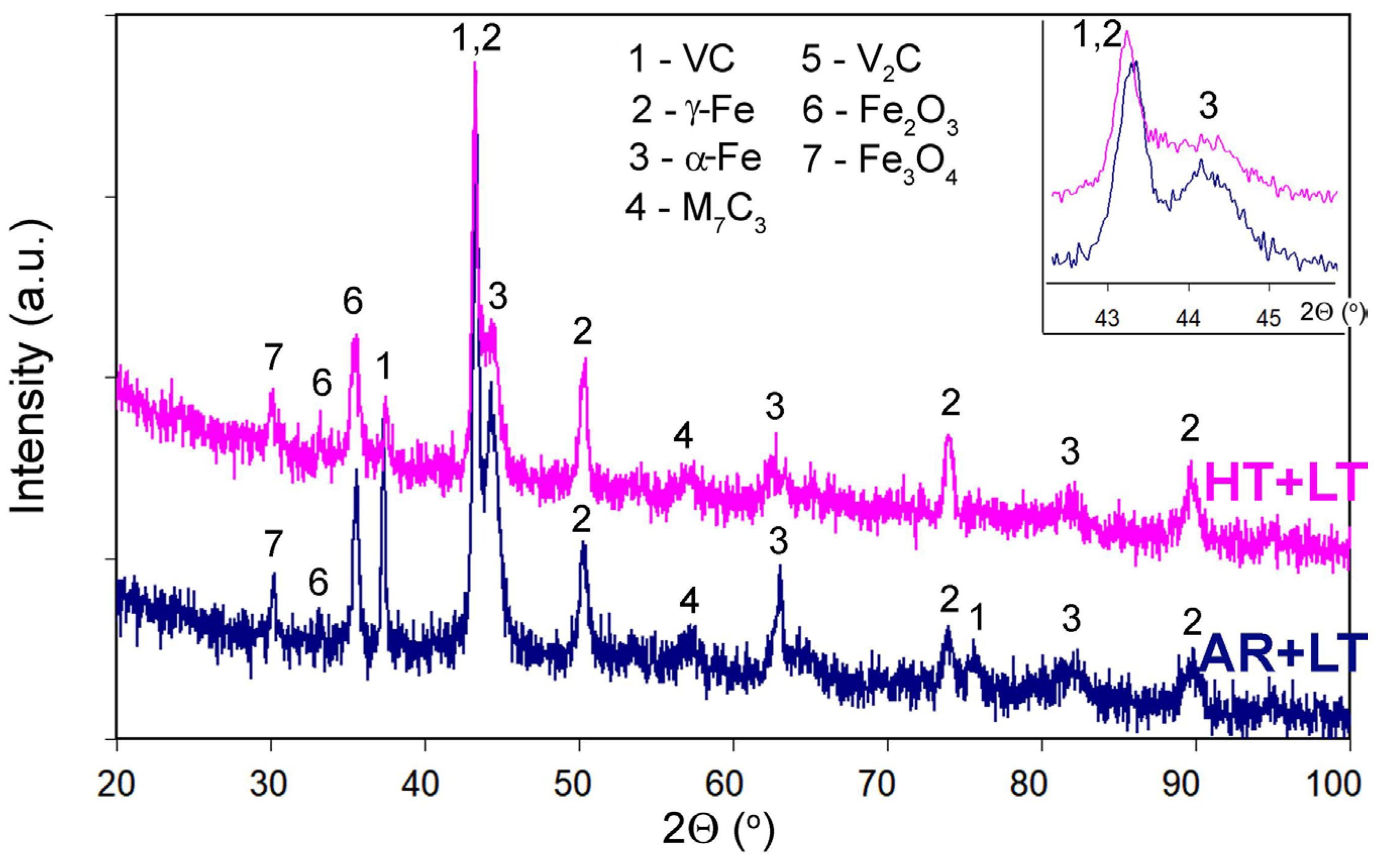
X-ray diffraction analysis of the as-received specimen (Figure 2) revealed distinct peaks corresponding to three phases: (a) α-Fe (the primary phase, with the highest intensity), (b) austenite (γ-Fe), and (c) vanadium carbide (as VC or V2C). Additionally, low-intensity diffraction maxima attributed to M7C3 carbide were observed, with characteristic peaks at (401), (422), and (731). Based on the XRD pattern, the volume fraction of retained austenite in the matrix was 7.1 vol.%.
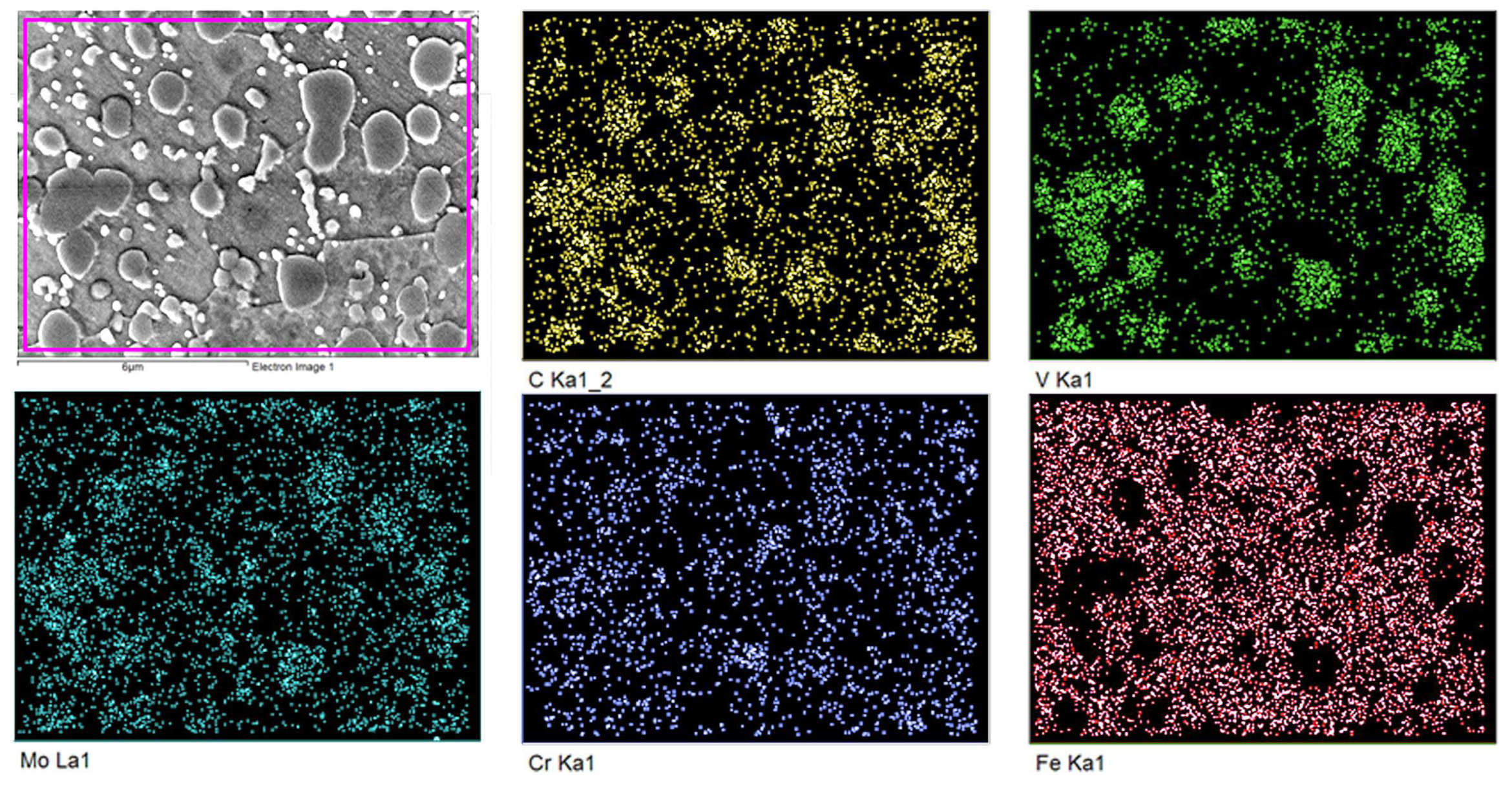
Energy-dispersive X-ray (EDX) spectroscopy was used to further identify the carbides through both mapping (Figure 3) and the point analysis modes. Coarse carbides contained approximately 58.0 at.% V, 11.01 at.% Mo, 5.5 at.% Cr and 1.5 at.% W. Medium-sized carbides (No. 2 in Figure 1a) were rich in chromium (25.8 at.%) and exhibited lower concentrations of other carbide-forming elements (3.5 at.% V, 2.0 at.% Mo, and 0.3 at.% W). Fine inclusions (No 3 in Figure 1b) were enriched in molybdenum (24.9 at.%) and tungsten (4.6 at.%), but depleted in chromium (4.8 at.%). The matrix, primarily iron-based, contained on average 2.7 at.% Cr, 1.0 at.% Si, 1.1 at.% V, 0.6 at.% Mo, and 0.3 at.% W. Based on the results of XRD and EDX analyses, the carbides were classified as follows:—Coarse carbides: MC-type (vanadium-based);—Medium-sized carbides: M7C3-type (chromium-based);—Fine carbides: M6C or MC-type (molybdenum/tungsten-based). This set of reinforcing carbide phases corresponded to a multi-component alloying principle [7,53,54], which is beneficial for enhancing the tribological performance of composite-structured alloys.
Secondary electron images (SEI) of the microstructure of the bulk heat-treated specimen are shown in Figure 1c,d. A reduction in carbide content was observed due to the partial dissolution of medium-sized and fine inclusions. The matrix transformed into an acicular martensitic structure, with fine precipitates located along the former grain boundaries. In the XRD pattern of the HT sample, (Figure 2), multiple peaks of varying intensity were observed, corresponding to the oxide phases Fe2O3 and Fe3O4, which formed at the surface during heat treatment [55]. The volume fraction of retained austenite increased compared to the as-received condition, reaching 24.8 vol.%. The density of the steel in a bulk heat-treated state was measured as 7.5081 ± 0.001 g/cm3.

3.2. Laser-Modified Structure

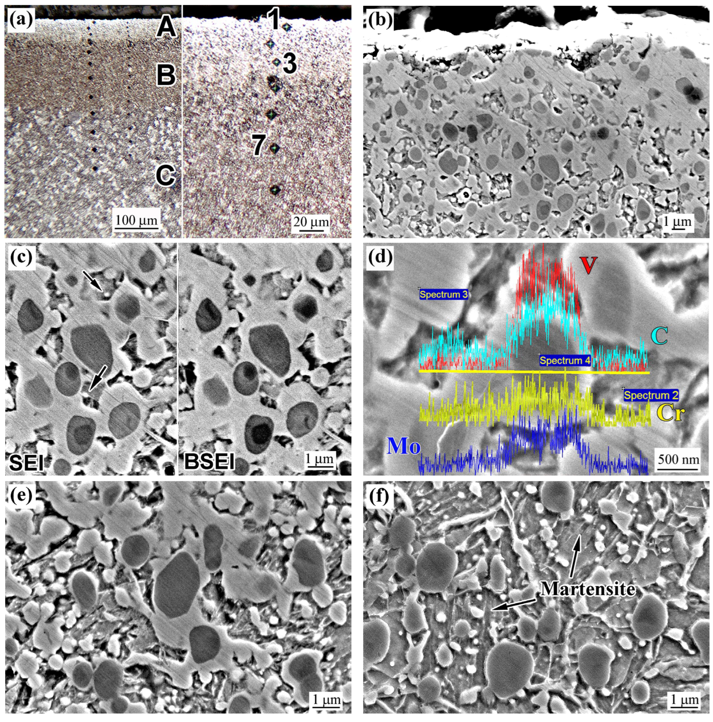
Figure 4 depicts the microstructure of as-received K390 steel after laser surface modification (AR+L specimen). Following laser processing, a modified surface layer was formed, with a total thickness of 200–220 µm (Figure 4a). This layer consisted of two distinct sub-layers: a finely dispersed subsurface layer A, approximately 50 µm thick, exhibiting brighter contrast; and a threefold thicker layer B with darker contrast. Beneath layer B, a coarse-grained base structure was observed, denoted as region C.
An oxide layer up to 1.5 µm thick was present on the top surface (Figure 4b). Beneath the surface, down to a depth of approximately 20 µm (at point 1 in Figure 4b), layer A exhibited distinctive structural features characterized by coarse granular carbides enveloped by a wide “shell” with a structureless, homogeneous pattern. This shell formed a continuous coarse network; within the gaps of this network, occasional matrix regions were visible, containing a few grainy carbides (indicated by the arrows in Figure 4c). In the BSE image, the shell displayed a brighter contrast compared to the carbides, suggesting enrichment with elements of higher atomic numbers. According to the elemental line distributions (Figure 4d), the shell was enriched in C, Cr, and Mo. Point EDX analysis revealed that the shell contained 8.2 at.% Cr and 2.0 at.% Mo (Spectrum 3, Figure 4d), which were 2–7 times higher than the concentrations found in the matrix (3.4 at.% and 0.3 at.%, respectively; Spectrum 2). Additionally, the shell was enriched in vanadium (2.3 at.%), cobalt (4.3 at.%), and tungsten (0.2 wt.%), exceeding the corresponding matrix values of 0.8 at.%, 2.9 at.%, and 0 at.%, respectively.
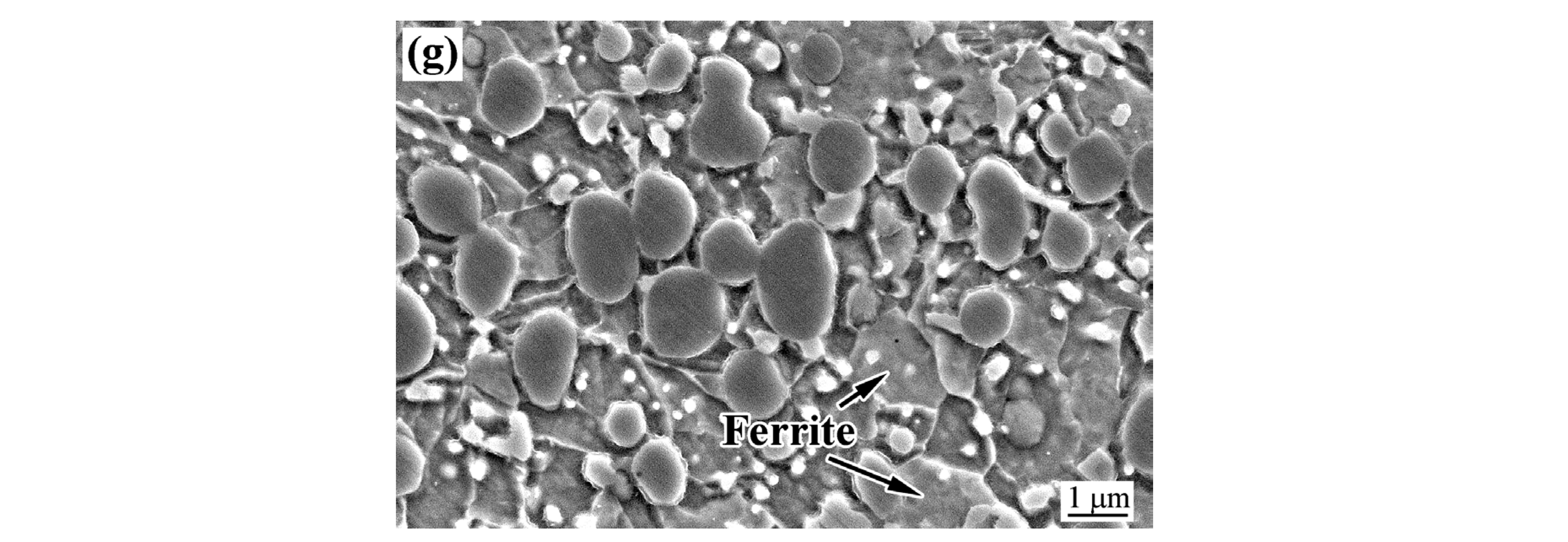
With increasing depth beyond 20 µm, the volume fraction of the shell structure notably decreased (as seen in Figure 4e, showing the microstructure at point 3). Deeper in layer B (at point 7), the presence of the shell was minimal; instead, numerous fine carbides were observed within the matrix, which consisted of acicular martensite (Figure 4f). Beyond layer B, the microstructure resembled that of the as-received condition, featuring coarse and fine carbides embedded in a ferritic matrix (Figure 4g).
Figure 5 presents the XRD pattern of the AR+L specimen. Compared to the as-received condition (Figure 2), a greater number of peaks were observed, attributed to the diffraction maxima of iron oxides (Fe2O3 and Fe3O4) and M7C3 carbide. The most significant changes were associated with variations in the intensity of the α-Fe and γ-Fe phase peaks, indicating a substantial increase in the retained austenite content within the steel matrix—up to 38.4 vol.% (see α-Fe and γ-Fe peaks in the inset of Figure 5).
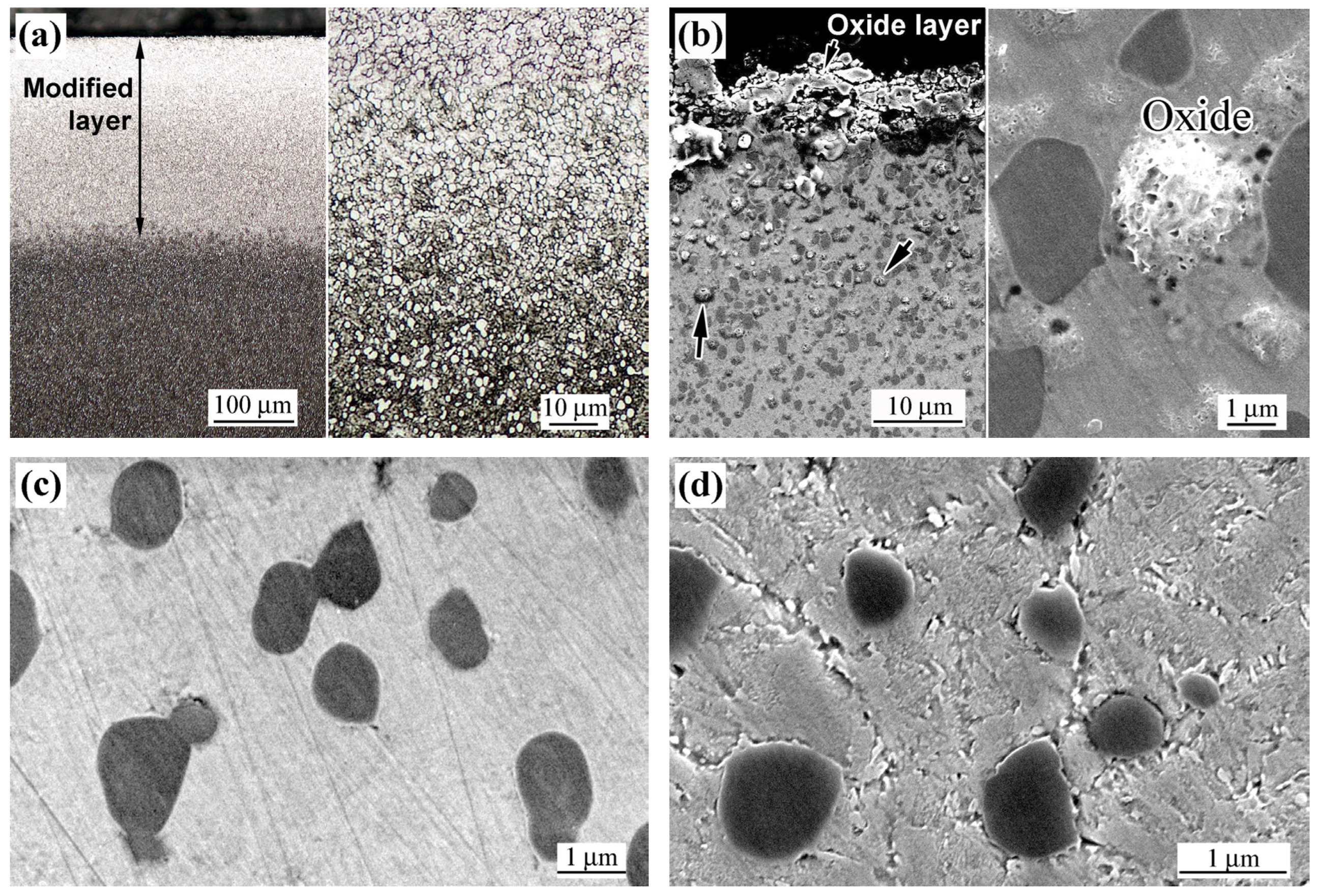
The microstructure of the bulk heat-treated, laser-modified specimen (HT+L) is shown in Figure 6. Laser processing produced a modified surface layer with a thickness of 240–250 µm, which exhibited significantly lower etching susceptibility than the underlying base structure (Figure 6a, left side). At the top of this layer, a loose oxide film measuring 5–10 µm in thickness was present. Beneath it, granular oxide inclusions ranging from 0.2 to 1.5 µm in diameter were observed to a depth of approximately 20 µm (indicated by arrows in Figure 6b). The oxide nature of these inclusions was confirmed by EDX analysis, which detected oxygen concentrations of 7–10 wt.%. Starting from the very surface, the microstructure consisted of coarse vanadium-based carbide inclusions embedded in a homogeneous, structureless matrix—similar to the “shell” observed in the AR+L specimen—where structural features were barely discernible (Figure 6c). With increasing depth beyond approximately 30–40 µm, the matrix gradually loses its “structureless” character: grain boundaries became discernible, accompanied by the appearance of fine precipitates along these boundaries (Figure 6a, right side; Figure 6d). Near the boundary of the modified layer and untreated base material, the matrix exhibited a distinct acicular martensitic structure (Figure 6e).
Figure 6f illustrates the depth-dependent distribution of the structureless matrix. In the AR+L specimen, this constituent occupied approximately 63% of the alloy volume near the surface (at a depth of 7–8 µm); however, its fraction decreased sharply with increasing depth and is no longer detectable beyond about 100 µm. In HT+L, the HT+L specimen exhibits a fully “structureless” matrix up to a depth of 30–40 µm. Quantitative assessment of this structural constituent in deeper regions was complicated since the matrix gradually evolved from the structureless pattern to the acicular martensite pattern (Figure 6c–e).
The XRD pattern of the HT+L specimen closely resembled that of the AR+L specimen, showing diffraction peaks corresponding to Fe2O3, Fe3O4, the (α-Fe + γ-Fe) matrix, and various carbide phases. Unlike the AR, HT, and AR+L specimens, austenite was predominant in the matrix, with a volume fraction of 54.7 vol.%. The density values of the AR+L and HT+L specimens were 7.5288 ± 0.002 g/cm3 and 7.5177 ± 0.002 g/cm3, respectively, closely matching those of the AR and HT states.

3.3. Microhardness Distribution

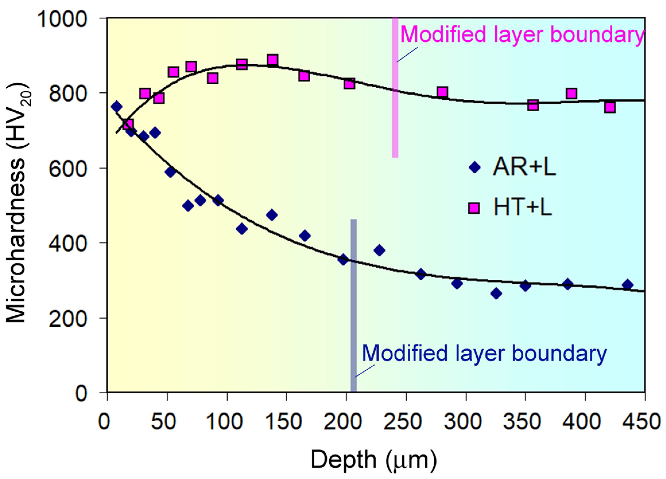
The microhardness distribution across the laser-modified layer is presented in Figure 7. In the AR+L specimen, the microhardness at a depth of 10 µm was 763 HV, gradually decreasing inward to about 700 HV at 20 µm, approximately 600 HV at 50 µm, and further to 360 HV at the boundary of the laser-modified layer. In the unaffected structure, the microhardness fluctuated within a range of 324–335 HV (average value of 331.5 ± 4.1 HV). Consequently, laser processing resulted in an approximately 160% increase in the microhardness of K390 steel compared to the as-received state.
Following combined treatment (HT+L), the microhardness near the surface (at a depth of about 20 µm) was 710 HV20. This lower value was attributed to the subsurface zone with an increased amount of retained austenite and granular oxides (Figure 6b). Inward from the surface, the hardness increased to 855 HV at a depth of approximately 550 µm and stabilised within 835–887 HV (mean value of 860.7 ± 53 HV20) up to a depth of 160–170 µm. In deeper zones, the microhardness gradually decreased to 800 HV20 at the boundary of the laser-modified layer, further stabilising at a level of 760–800 HV20 within the non-modified base structure (mean value of 777.8 ± 48 HV20). These data indicated that laser processing increased the hardness of K390 steel by 84 HV (a 10% increase) compared to the bulk heat-treated structure.

3.4. EBSD Characterisation

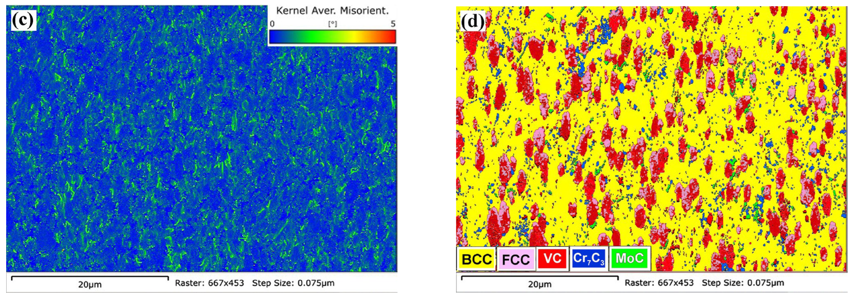
Figure 8 and Figure 9 present the results of EBSD studies of AR+L and HT+L samples, respectively. The images were taken in the plane of the cross-sectional plane of the samples, within the laser-modified layer, at a depth of approximately 50 µm from the surface. From the inverse pole figure (IPF) map (Figure 8a), it was inferred that the grains in the modified layer had an anisotropic shape, elongated perpendicular to the surface, i.e., parallel to the heat dissipation direction during laser processing. However, there was no pronounced texture, as the IPF map showed various crystallographic orientations in different grains. The EBSD-calculated average grain size is 2.26 µm, where grain referred to all structural elements distinguished by crystallographic orientation, including carbide particles. Figure 8b, showing band contrast (BC) and grain boundary (GB) maps, indicated that high-angle grain boundaries (HAGBs) (>10°) predominated over low-angle grain boundaries (LAGBs), accounting for 70.8% of the total. According to the kernel average misorientation (KAM) map, zones of local lattice distortions were relatively uniformly distributed within the analysed area; the average KAM value was 0.53°, indicating a moderate level of microstrains. Figure 8d shows the results of phase constituent identification in the AR+L sample. The matrix was predominantly composed of α-Fe (BCC lattice), while among the carbides, vanadium carbide (VC) prevailed; (molybdenum carbide MoC and chromium carbide Cr7C3 were also detected). Austenite (FCC lattice) regions were spatially associated with VC carbides, as austenite appeared to envelop the vanadium carbides.
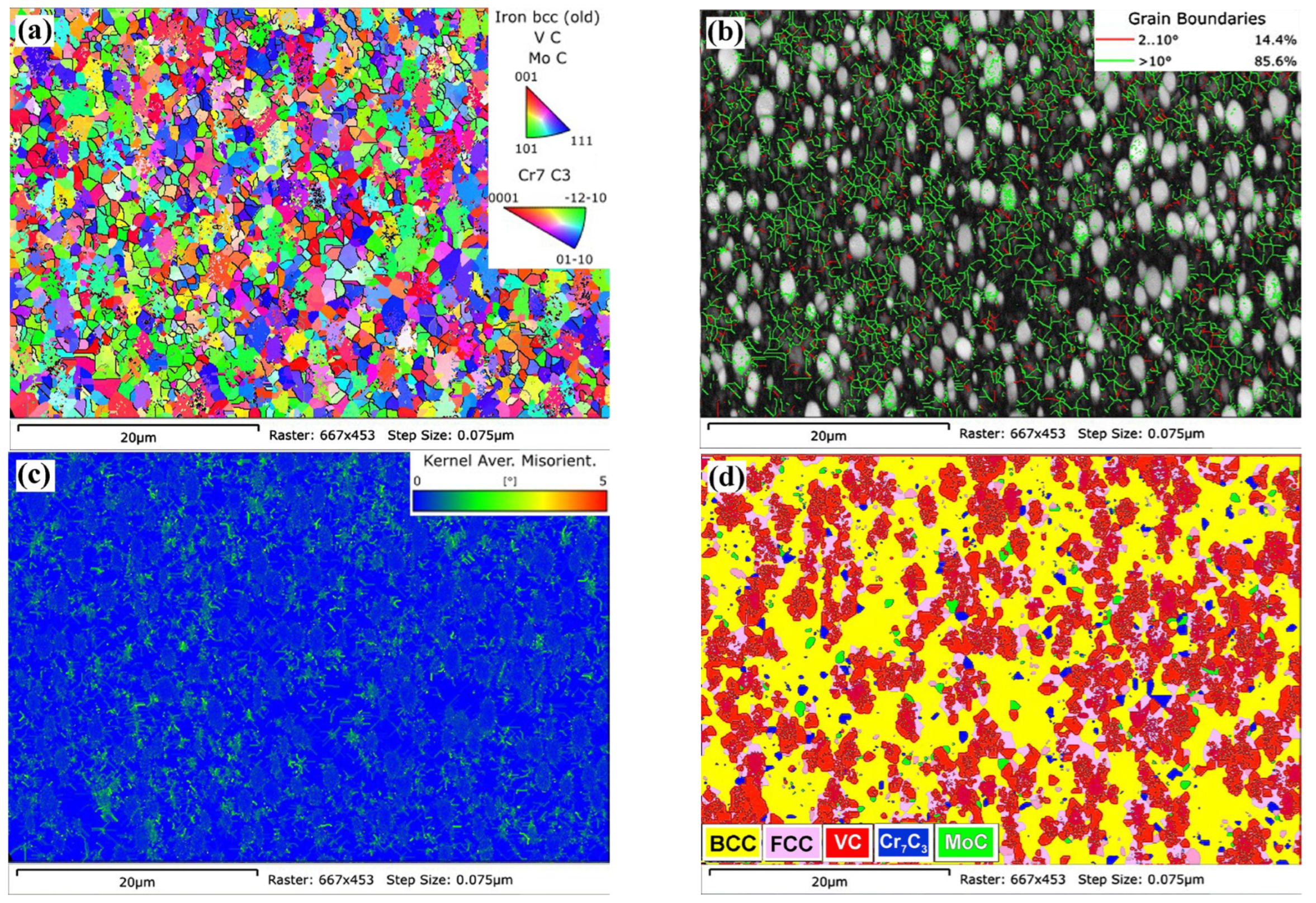
The results of the EBSD analysis of the HT+L sample differed from those of the AR+L sample showing a finer grain size (approximately half), measured at 0.98 µm (Figure 9a). This difference was associated with a twofold reduction in the fraction of low-angle grain boundaries (Figure 9b), which leads to a decreased intensity in the KAM map (the average KAM value was 0.25°, indicating a lower density of geometrically necessary dislocations formed as a result of laser processing) (Figure 9c). The qualitative phase composition (set of phases) of the HT+L alloy (Figure 9d) was similar to that of the AR+L sample. Notable features included slightly larger sizes of regions identified by EBSD as VC, MoC, and Cr7C3.

3.5. Wear Properties

Figure 10a–d present 3D views of wear tracks, revealing notable variations in track dimensions depending on the alloy’s state, as supported by the wear track profiles in Figure 10e. The as-received steel exhibited the largest average track width and maximum depth, measuring 210 μm and 1.31 μm, respectively (Figure 10a). In contrast, the bulk heat-treated state showed reduced wear track dimensions of 180 μm in width and 0.55 μm in depth, reflecting enhanced resistance to sliding wear. Laser modification further enhanced the alloy’s wear properties: in AR+L specimens, the wear track parameters decreased to 162 μm and 0.32 μm, respectively, indicating better wear resistance compared to the bulk heat-treated state. The HT+L specimen showed the highest wear resistance, with the smallest track width and depth of 148 μm and 0.28 μm, respectively. Additionally, the friction tracks of all samples were characterized by the absence of lateral ridges, which typically appear on ductile materials during sliding tests [52,56].
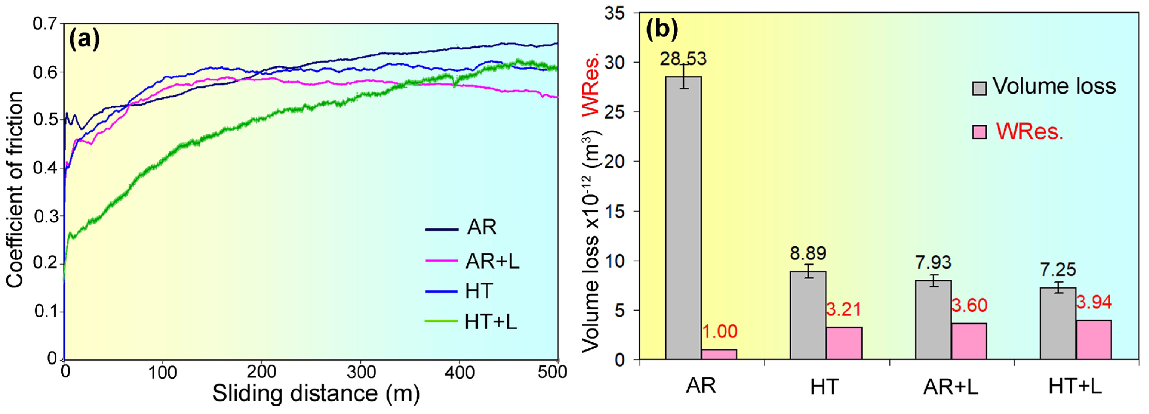
Figure 11a illustrates the variation in the coefficient of friction (CoF) during testing. Most samples showed a similar CoF trend, with a sharp increase over the first 100–150 metres of sliding, followed by either stabilisation or slight changes in CoF values. The AR sample had the highest friction forces, with the CoF rising steadily to 0.66 by the test’s completion. In the AR+L sample, the CoF peaked at 0.59 after 100 metres and then gradually declined to 0.54–0.55. Heat-treated samples (HT and HT+L) reached a CoF of 0.60–0.62; the HT+L sample showed the slowest CoF increase at the beginning of testing among all samples, while in the HT sample, the CoF stabilised after approximately 150 metres of sliding. Based on the CoF values from the final 100 metres, the samples were ranked by increasing CoF as follows: AR+L < (HT, HT+L) < AR.
Figure 11b shows the volume loss values (ΔV) derived from the wear track profiling. The as-received (AR) sample exhibited the highest volume loss (28.53 × 10⁻¹² m3), serving as the reference for the wear resistance coefficient calculation (WRes. = 1.0). In contrast, the HT, AR+L, and HT+L samples showed substantially lower volume loss ((3.21–3.94) × 10−12 m3), indicating 3–4 times higher wear resistance than the AR sample. Laser-treated samples achieved the highest wear resistance coefficients: WRes. = 3.60 for AR+L and WRes. = 3.94 for HT+L. According to these findings, the samples were ranked by wear resistance in the following order: AR < HT < AR+L < HT+L.

3.6. Worn Surface Characterisation

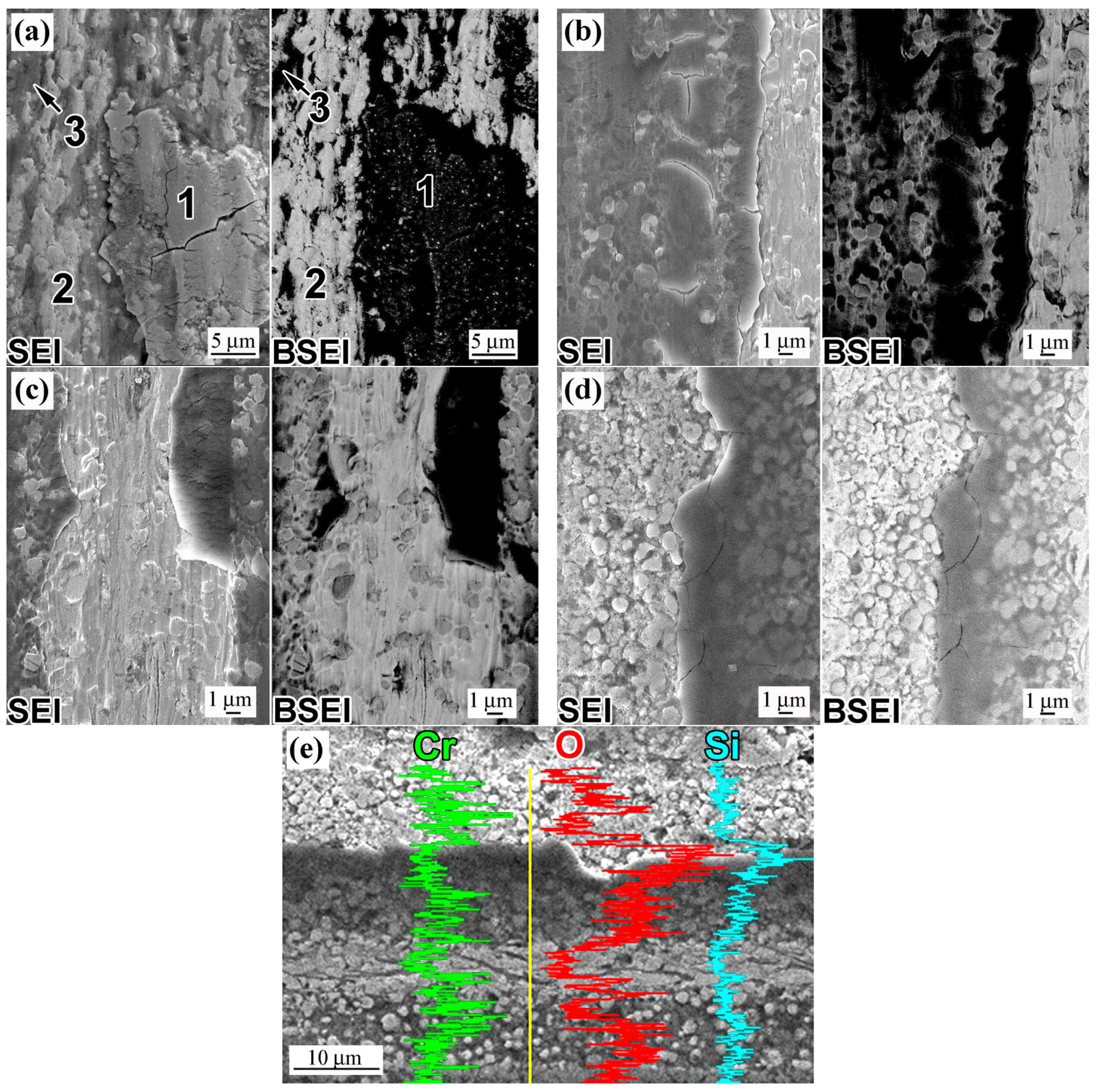
SEM examination of the wear track surface (Figure 12) revealed the presence of tribo-layers (oxide films), whose thickness varied depending on the processing applied to the specimen. The wear track of the as-received specimen was characterised by thick tribo-layers (denoted by number 1 in Figure 12a), exhibiting cracks and delamination. Beneath the detached oxide films, fresh (undeformed) surface areas were exposed (indicated by number 2 in Figure 12a). In backscattered electron images, the thick tribo-layers appeared dark due to enrichment with light elements—primarily oxygen (Figure 12a, right side). In contrast, the fresh areas where film detachment occurred exhibited brighter BSE contrast. In addition to thick tribo-layers and fresh regions, deformed areas were also observed (denoted as 3 in Figure 12a) covered by a thin oxide scale, representing the initial stage of thick film formation.
The wear tracks of specimens subjected to bulk heat treatment and/or laser processing exhibited much thinner tribo-layers with fewer cracks (Figure 12b–d). A distinctive feature of the oxide tribo-layers on the HT, AR+L, and HT+L specimens—indicating their reduced thickness—was their transparency to the electron beam, which allowed visualisation of the underlying microstructure of the base metal in secondary electron images (SEI), specifically the coarse vanadium carbides. In contrast, the thick films on the AR specimen were opaque to the electron beam.
The oxide origin of the tribo-layers was confirmed by EDX analysis, the results of which are presented in Table 1. The analysis was performed on the oxide scale (at its thickest location), as well as in the deformed and fresh areas. In the AR specimen, the thick oxide film contained 56.8 at.% oxygen and showed some enrichment in vanadium (4.3 at.%) and molybdenum (1.0 at.%). In the deformed and fresh regions, the oxygen content was significantly lower at 10.6 at.% and 4.7 at.%, respectively; the concentrations of V and Mo also decreased in these areas compared to the thick oxide film. In the AR+L specimen, the oxide film contained 5.7 at.% less oxygen and slightly higher concentrations of Cr, V, and Mo compared to the AR specimen. The HT+L specimen exhibited the lowest oxygen concentration in the tribo-layer (32.9 at.%). For both AR+L and HT+L specimens, the concentrations of the above-mentioned elements decreased from the thick oxide region toward the fresh area. In all specimens, the thick oxide region showed elevated silicon content (5.1–8.0 at.%), suggesting that these films were complex Fe–O–Si spinel-type compounds ((Fe,Si)2O4) [55]. In all specimens, the silicon content at the analysed points decreased from the thick oxide to the fresh area, approaching 1.0–1.4 at.%, which was the Si baseline concentration in the alloy. Unlike silicon, chromium played a negligible role in oxide formation during wear. These trends were illustrated by the elemental distribution across the wear track (Figure 12e), which showed pronounced spikes in oxygen and silicon attributed to the thicker regions of the oxide films. No significant carbide fracture or spalling was observed within the wear tracks.

4. Discussion

Microstructure Evolution

The presented results clearly demonstrate that laser surface treatment significantly enhanced the hardness and tribological performance of K390 tool steel, potentially extending the operational lifespan of tooling in cold-forming applications, including those involving high-strength, strain-hardened steels. Metallographic studies attributed these improvements to the formation of a distinct modified microstructural state in the surface layers, induced by laser processing. Briefly, this state was characterised by the appearance of homogeneous matrix regions surrounding large carbide inclusions, where no discernible structural features were observed under OM and SEM examination—even at high magnifications (30–40 kX). This state was accompanied by the partial dissolution of carbides, particularly their fine fraction. Insights into this microstructure were further supported by XRD analysis, which revealed a pronounced displacement of α- and γ-phase peaks toward lower 2θ angles caused by laser treatment. This shift in peak positions was consistent with lattice parameter changes described by Equation (2):
a = h 2 + k 2 + l 2 λ 2 sin θ ,
where h, k, and l refer to the indices of the crystallographic plane involved in diffraction, and λ stands for the wavelength of the X-ray beam.
Based on Equation (2), the lattice parameters of the α-Fe and γ-Fe phases were determined from the positions of their respective (110)BCC and (111)FCC diffraction peaks (Figure 2 and Figure 5), with the calculated values shown in Figure 13b. The data clearly indicated that laser processing significantly increased the lattice parameter of the α-phase—from 2.866–2.867 Å (AR, HT) to 2.887 Å in the AR+L sample and to 2.897 Å in the HT+L sample. A similar trend was observed for the γ-phase, where the lattice parameter increased from 3.596 Å (HT) to 3.611 Å (AR+L) and to 3.622 Å (HT+L). The observed increase in the lattice parameter was associated with a higher carbon content resulting from the dissolution of fine carbides during laser heating [57]. It was well established that the lattice parameter of steel was directly related to the concentration of dissolved carbon [58]. For martensite (in steels containing more than 0.6 wt.% C) and austenite, these relationships were governed by the Honda–Nishiyama model (Equation (3)) [57] and Equation (4) [59], respectively:
cM/aM = 1 + 0.045xC,
aγ = 0.3556 + 0.0453xC + 0.000095xMn,
where aM and cM denotes the lattice parameters of tetragonal martensite (in angstroms); aγ denotes the lattice parameter (in angstroms), while xC and xMn represent the weight percentages of carbon and manganese in retained austenite, respectively.
Equation (3) was used to estimate carbon concentrations in retained austenite following laser modification, which measured 1.20% (AR+L) and 1.44% (HT+L), representing a 1.5–1.8-fold increase compared to the retained austenite in the HT alloy. This carbon enrichment stabilised the austenite, increasing RA volume fraction to 38.4% and 54.7%, respectively. Increased carbon content also induced pronounced lattice distortion in α-Fe, which likely contributed to the enhanced hardness of martensite. This effect was indirectly supported by the high hardness values (700–763 HV20) measured in the subsurface region of the AR+L sample (Figure 7), despite the notable presence of the softer retained austenite phase. The HT+L sample showed comparable hardness at the same depth, even with a higher retained austenite content. In deeper layers (50–150 µm), where the retained austenite fraction was lower, hardness exceeded that of conventional bulk heat treatment. Carbon enrichment primarily resulted from the dissolution of fine chromium and molybdenum carbides, along with partial dissolution of coarse vanadium carbides during laser heating. The latter was evidenced by the austenitic envelope surrounding coarse VC carbides, as observed in EBSD analysis (Figure 8d and Figure 9d).
Beyond carbon enrichment in the α- and γ-phases, the high hardness of the modified layer was partially attributed to lattice micro-distortions induced by laser quenching. This was evidenced by the pronounced broadening of diffraction peaks observed in the XRD patterns of laser-modified samples, resembling those of amorphous alloys (Figure 13a). Peak broadening was evaluated using the full width at half maximum (FWHM) parameter. The variation in FWHM for α-phase reflections depending on sample treatment is shown in Figure 13c. A clear trend was observed: peak broadening increased significantly from the HT sample to AR+L and further to HT+L. As per [60], the XRD peak broadening primarily resulted from reduced crystallite size and microstrains, including the lattice defects. To unravel these effects, the Williamson–Hall method was employed, enabling separate quantification of crystallite size reduction and lattice strain contributions [61]:
β h k l cos θ = K λ D + 4 ε sin θ .
In Equation (5), βhkl denotes the FWHM, D is the size of the coherent scattering domains (crystallite size), K is the shape factor (taken as 0.891), λ represents the wavelength of X-radiation, θ is the Bragg angle, and ε corresponds to the crystal microstrain, calculated by Equation (6):
ε = β h k l 4 tan θ .
The average size of crystalline domains was estimated by Debye-Scherrer’s formula (Equation (7)) [62]:
D = K λ β h k l cos θ .
Williamson–Hall plots, using “4sin(θ)” as the horizontal axis and “βhklcos(θ)” as the vertical axis (Figure 13d), were employed to derive the experimental values of D and ε. The Y-intercept of the fitted line provided the crystallite size, while its slope to the X-axis indicated the microstrain. Using the obtained values of D and ε, the dislocation density (ρ) was estimated via the Williamson–Smallman approach (Equation (8)) [63]:
ρ = 3 k ε D b ,
where b is the Burgers vector magnitude (taken as 2.58 × 10⁻¹⁰ m [64]), and k is a parameter reflecting the elastic properties of the alloy and the dislocation configuration (taken as 1.2 [63]).
The results of D and ρXRD evaluations are presented in Figure 13e. They indicate a progressive decrease in crystallite size from the AR specimen to the HT+L specimen, ultimately reaching an ultra-fine value of 8.3 nm. These findings align with EBSD results, which revealed a 2.3-fold decrease in grain size in HT+L compared to AR+L sample. Overall, laser modification reduced crystallite size by a factor of 4 to 7 relative to the initial (untreated) state. The fine-grained structure of the laser-modified specimens is primarily attributed to the high heating and cooling rates inherent to the laser treatment process. Upon heating, K390 steel underwent an α-Fe → γ-Fe phase transformation. The resulting austenite grain size was determined by the critical radius of γ-phase nuclei (R*γ), which can be expressed by Equation (9) [65,66]:
R γ * = 2 γ T o Δ H Δ T ,
where ΔH is the latent heat released during the phase transition, γ is the surface energy at the interface, T0 is equilibrium phase transition temperature, and ΔT is the amount of overheating above T0.
From Equation (9), the critical radius of the γ-phase was inversely proportional to ΔT. As reported in [67], laser heating rates could reach 103–104 K/s, causing a shift of the critical transformation points to higher temperatures and increasing the degree of overheating (ΔT). Consequently, the critical nucleus size of austenite decreased, suggesting the formation of ultra-fine grains at the completion of the phase transformation. These grains remained small due to the rapid transition from heating to cooling, driven by heat conduction into the bulk of the specimen. As per [67,68], the cooling rate was comparable to the heating rate and significantly exceeded the critical cooling rate required for martensitic transformation via the shear mechanism in the steels [69]. As such, within these ultra-fine austenite grains, cooling produced the structureless fine-needle martensite [70], which could not be resolved by optical or scanning electron microscopy. Such martensite was characterized by elevated hardness and fracture toughness, which enhanced the tribological properties of the laser-modified surface. The high thermal gradients (stresses) induced by rapid cooling promoted accommodating shear strains, leading to a high density of lattice defects. As shown in Figure 13e, in laser-treated samples, the dislocation density reached high values: 6.4 × 10¹⁴ m−2 (AR+L) and 2.6 × 10¹⁵ m−2 (HT+L), characteristic for the martensite transformation [71]. The contribution of dislocations (Δσρ) to the overall yield strength of the modified layer which was estimated by the Taylor law (Equation (10)) [72]:
Δ σ ρ = α M G b ρ 1 / 2
where, α is a coefficient reflecting the nature of the dislocation interaction during strain hardening, set as 0.25 [73]. M is the Taylor factor, taken as 2.73 for α-Fe [74]. G denotes the shear modulus, equal to 81.6 GPa for α-Fe. b is the magnitude of the Burgers vector. ρ is the dislocations density.
The dislocation strengthening contributions for the laser modified specimens AR+L and HT+L were calculated to be 363 MPa and 728 MPa, respectively. According to Pavlina and van Tyne [75], the yield tensile strength (YTS) of steel with martensitic microstructure correlates linearly with its hardness (HV):
YTS = 110.9 + 2.507 · HV.
Based on Equation (11), the dislocation-related contribution to the hardness of the laser-modified samples can be roughly estimated as 100.7 HV (AR+L) and 246.3 HV (HT+L), representing a substantial addition that accounted for 14% and 34% of the total microhardness, respectively.
In the initial state, the matrix consisted of a low-carbon phase (ferrite) while nearly all carbon was concentrated within carbide precipitates. To achieve high hardness in the quenched condition, the solid solution had to be enriched with carbon. This enrichment occurred in K390 through partial dissolution of carbides during heating into the austenitic domain, either via bulk heat treatment or laser-induced heating. Upon cooling, the carbon-saturated austenite transformed into high-carbon martensite, which imparted elevated hardness to the steel in its quenched state. A portion of the carbon- and alloy-enriched γ-phase remained in the microstructure as retained austenite. The carbide-forming alloying elements (Mo, W, V, Cr), dissolved during carbide dissolution, also contributed to the retained austenite content as well as to the steel’s hardenability [76]. Since the austenite was in an ultrafine-grain state prior to martensitic transformation, quenching resulted in the formation of a nanoscale conglomerate of martensite and retained austenite, appearing as homogeneous, structureless zones (Figure 4c and Figure 6c). These martensite–austenite (M–A) regions were located adjacent to carbide inclusions—areas where local carbide dissolution and matrix carbon enrichment occurred. In regions distant from carbides, the lack of carbon enrichment led to predominant martensite formation upon cooling. The volumetric fraction of M–A structure decreased with increasing depth from the surface (Figure 6e). This trend was clearly observed in the AR+L specimen, where the M–A/martensite interface was distinctly defined. In contrast, in HT+L specimens, the matrix gradually transitioned from a structureless morphology into a fully martensitic one, thereby hindering accurate quantification of the M–A volume fraction evolution. At greater depths within the laser-modified layer of HT+L, dispersed carbide particles were observed along prior austenitic grain boundaries (Figure 6d,e). Their precipitation was presumably facilitated by grain boundary diffusion, which promoted the migration of alloying elements along grain interfaces [77]. The observed structural gradient in the matrix (M-A → (M–A + martensite) → martensite) corresponded to the thermal gradient across the specimen’s cross-section during laser heating. In near-surface regions, elevated temperatures intensified carbide dissolution, thus leading to pronounced austenite enrichment with carbon and alloying elements resulting in higher M–A volume fraction.
The hardness profile across the laser-modified layer was primarily influenced by the ratio of acicular martensite to M–A regions within the matrix, as well as the inherent hardness of these structural components and the hardness of ceramic particles [78]. Although the near-surface hardness (up to ~20 µm depth) of the AR+L and HT+L specimens was comparable (710–763 HV20), their microstructures differed significantly, particularly in terms of the volume fraction of the M–A agglomerate: in the AR+L specimen, the M–A phase occupied up to 63% of the matrix, whereas in the HT+L specimen, this fraction reached 100%. The equivalence in hardness indirectly suggested that martensite within the M–A mixture in HT+L was harder, likely due to the higher carbon content in the crystal lattice. This assumption was supported by XRD data on lattice parameters and carbon concentration in retained austenite (Figure 13b). Notably, at deeper layers (~100 µm), the modified layer of the HT+L specimen exhibited a significant hardness advantage over AR+L (860 HV20 vs. 510 HV20, respectively). These differences were attributed to the distinct pre-treatment histories of the specimens, specifically the application of bulk heat treatment prior to laser modification. It was hypothesised that the bulk treatment facilitated deeper carbon enrichment of the solid solution through more complete carbide dissolution during prolonged (1 h) austenitization at 1180 °C, thereby effectively preparing the microstructure for subsequent laser quenching. In contrast, carbide dissolution in the AR+L specimen occurred over a much shorter duration during laser heating, resulting in a lower degree of carbon enrichment in the matrix.
With an identical surface hardness, the HT+L specimen demonstrated superior wear resistance compared to the AR+L specimen. This improved wear resistance was attributed to: (a) a higher volumetric fraction of the M–A constituent, featuring a nanoscale structure with enhanced resistance to fracture [79,80]; (b) increased martensite hardness within the M–A regions; (c) potential susceptibility of retained austenite to strain-induced martensitic transformation, which could have enhanced surface hardness and durability [81,82]. Beneath the subsurface layers, the HT+L sample contained layers with even greater hardness (850–890 HV20), offering a robust reserve of mechanical integrity for prolonged tool operation under severe wear conditions.
Laser-induced modification of K390 steel resulted in a composite structure that integrated carbides within a nanostructured matrix. This configuration enabled wear to proceed via the most favourable mechanism—through the formation and detachment of oxide tribo-layers, without large-scale carbide damage or intense matrix deformation. This wear behaviour significantly extended tool life [83], particularly considering that oxide films acted as solid lubricants under dry sliding conditions, reducing the coefficient of friction and protecting the surface from adhesion and galling processes [84] (Figure 11).
In conclusion, the combined approach, integrating bulk heat treatment and non-melting laser hardening, offered clear advantages over laser hardening of the as-received base structure. This improvement was due not only to the enhanced hardness of the modified layer, but also to the presence of a hardened substrate throughout the entire cross-section of the sample, formed during pre-laser bulk heat treatment, which effectively prevented punch-through of the hardened surface under the high contact loads typical of stamping tool applications.

5. Conclusions

This study investigated the effects of non-melting laser surface treatment on the microstructure, phase composition, hardness, and tribological performance of powder-metallurgical K390 tool steel of composite metal matrix–carbides structure, and the following conclusions were drawn.
  • In the as-received condition, K390 steel exhibited a ferritic matrix containing a uniform dispersion of coarse VC carbides and finer M7C3 and M6C/MC carbides, with a total carbide volume fraction of 36.2%, and a retained austenite content of 7.1%. After bulk heat treatment (1 h at 1180 °C followed by quenching and triple 500 °C tempering), the matrix transformed into a fully martensitic structure with a lower amount of carbides and increased retained austenite content (up to 18.3%).
  • Non-melting laser surface treatment produced a modified surface layer up to 250 µm thick, composed of acicular martensite, retained austenite, and carbides. In regions where carbides partially dissolved and enriched the matrix with carbon, a homogeneous, structureless phase mixture of nanosized constituents (martensite and retained austenite) formed around the carbides, contributing to enhanced mechanical performance.
  • Laser heating induced partial dissolution of fine carbides, resulting in matrix saturation with carbon and alloying elements, which in turn led to an increase in lattice parameters and the volume fraction of retained austenite. Preceding bulk heat treatment promoted more extensive carbide dissolution, enabling deeper carbon enrichment of the matrix. As a result, the retained austenite fraction increased from 7.1% in the as-received state to 38.4% in AR+L and 54.7% in HT+L specimens, with corresponding carbon contents of 1.20 wt.% and 1.44 wt.%, respectively.
  • Laser modification led to a substantial microhardness improvement: up to 700–763 HV20 near the surface in AR+L and 855–890 HV20 in deeper zones of HT+L, compared to an average 331.5 HV20 in the as-received state and 777.8 HV20 in the bulk heat-treated condition. This enhancement was attributed to the formation of carbon-enriched martensite, elevated dislocation density (up to 2.6 × 10¹⁵ m−2), and ultrafine-crystallite size (as small as 8.3 nm).
  • Tribological testing confirmed superior wear resistance in laser-modified specimens, particularly HT+L, which exhibited a 3.94-fold reduction in volume loss and a lower friction coefficient compared to the untreated state. This improvement was attributed to the most favourable wear mechanism—formation and gradual detachment of oxide tribo-layers—occurring without extensive carbide degradation or severe matrix deformation.
  • The combined approach of bulk heat treatment followed by non-melting laser surface modification offered clear advantages over laser hardening of the as-received base structure. This method produced a robust, graded microstructure, making it well-suited for demanding tooling applications involving extreme contact loads during cold stamping and forming.

Author Contributions

Conceptualization, Y.C. and V.E.; methodology, Y.C., V.E., I.P. and F.K.; validation, I.S. and I.P.; formal analysis, T.K. and I.S.; investigation, Y.B., B.E., I.S., F.K. and T.K.; resources, Y.C., V.E., I.P. and B.E.; data curation, T.K.; writing—original draft preparation, Y.C., V.E. and Y.B.; writing—review and editing, Y.C., V.E. and Y.B.; visualization, B.E., I.S.; supervision, Y.C. and V.E.; project administration, B.E.; funding acquisition, Y.C. and B.E. All authors have read and agreed to the published version of the manuscript.

Funding

This research was financially supported by the Slovak Research and Development Agency (within the project APVV-24-0074).

Institutional Review Board Statement

Not applicable.

Informed Consent Statement

Not applicable.

Data Availability Statement

The original contributions presented in this study are included in the article. Further inquiries can be directed to the corresponding author.

Acknowledgments

Bohdan Efremenko, Ivan Sili, and Taras Kovbasiuk acknowledge the financial support within the project funded by the Ministry of Education and Science of Ukraine (project 0125U001980).

Conflicts of Interest

The authors declare no conflicts of interest.

Abbreviations

The following abbreviations are used in this manuscript:
ARAs-received
AR+LAs-received with laser processing
BSEIBackscattered electron image
EBSDElectron backscatter diffraction
EDXEnergy-dispersive X-ray analysis
HAGBHigh-angle grain boundary
HAZHeat-affected zone
HTBulk heat-treated
HT+LBulk heat-treated with laser processing
KAMKernel average misorientation
LAGBLow-angle grain boundary
LSTSurface laser treatment
OMOptical microscopy
PMPowder metallurgy
RARetained austenite
SEISecondary electron image
SEMScanning electron microscopy
XRDX-ray diffraction

References

  1. Böhler K390 MICROCLEAN. 2024. Available online: https://www.us.bohler.com/en-us/products/k390-microclean/ (accessed on 28 September 2025).
  2. Czupryński, A. Microstructure and Abrasive Wear Resistance of Metal Matrix Composite Coatings Deposited on Steel Grade AISI 4715 by Powder Plasma Transferred Arc Welding Part 2. Mechanical and Structural Properties of a Nickel-Based Alloy Surface Layer Reinforced with Particles of Tungsten Carbide and Synthetic Metal–Diamond Composite. Materials 2021, 14, 2805. [Google Scholar] [CrossRef]
  3. Duriagina, Z.A.; Romanyshyn, M.R.; Kulyk, V.V.; Kovbasiuk, T.M.; Trostianchyn, A.M.; Lemishka, I.A. The character of the structure formation of model alloys of the Fe-Cr-(Zr, Zr-B) system synthesized by powder metallurgy. J. Achiev. Mater. Manuf. Eng. 2020, 100, 49. [Google Scholar] [CrossRef]
  4. Nemec, M.; Jurci, P.; Kosnacova, P.; Kucerova, M. Evaluation of structural isotropy of Cr-V ledeburitic steel made by powder metallurgy of rapidly solidified particles. Kov. Mater. Met. Mater. 2016, 54, 453. [Google Scholar] [CrossRef]
  5. Tóth, L.; Fábián, R.E.; Pinke, P.; Kovács, T.A.; Nabiałek, M.; Sandu, A.V.; Vizureanu, P. Comparison of the Properties of Cold Work Tool Steels with the Same Hardness but Different Manufacturing Processes The required important properties. Arch. Metall. Mater. 2024, 69, 809. [Google Scholar] [CrossRef]
  6. Efremenko, V.G.; Shimizu, K.; Cheiliakh, A.P.; Kozarevs’ka, T.V.; Chabak, Y.G.; Hara, H.; Kusumoto, K. Abrasive wear resistance of spheroidal vanadium carbide cast irons. J. Frict. Wear 2013, 34, 466. [Google Scholar] [CrossRef]
  7. Efremenko, V.G.; Shimizu, K.; Cheiliakh, A.P.; Pastukhova, T.V.; Chabak, Y.G.; Kusumoto, K. Abrasive resistance of metastable V–Cr–Mn–Ni spheroidal carbide cast irons using the factorial design method. Int. J. Miner. Metall. Mater. 2016, 23, 645. [Google Scholar] [CrossRef]
  8. González-Pociño, A.; Alvarez-Antolin, F.; Peral-Martinez, L.B. Effects of Nitriding and Thermal Processing on Wear and Corrosion Resistance of Vanadis 8 Steel. Coatings 2024, 14, 1066. [Google Scholar] [CrossRef]
  9. Surekha, K.; Els-Botes, A. Effect of Cryotreatment on Tool Wear Behaviour of Bohler K390 and AISI H13 Tool Steel During Friction Stir Welding of Copper. Trans. Indian. Inst. Met. 2012, 65, 259. [Google Scholar] [CrossRef]
  10. Trembach, B.; Silchenko, Y.; Balenko, O.; Hlachev, D.; Kulahin, K.; Heiko, H.; Bellorin-Herrera, O.; Khabosha, S.; Zakovorotnyi, O.; Trembach, I. Study of the hardfacing process using self-shielding flux-cored wire with an exothermic addition with a combined oxidizer of the Al-(CuO/Fe2O3) system. Int. J. Adv. Manuf. Technol. 2024, 134, 309. [Google Scholar] [CrossRef]
  11. Efremenko, B.V.; Shimizu, K.; Espallargas, N.; Efremenko, V.G.; Kusumoto, K.; Chabak, Y.G.; Belik, A.G.; Chigarev, V.V.; Zurnadzhy, V.I. High-temperature solid particle erosion of Cr-Ni-Fe-C arc cladded coatings. Wear 2020, 460–461, 203439. [Google Scholar] [CrossRef]
  12. Loskutova, T.; Hatala, M.; Pogrebova, I.; Nikitina, N.; Bobina, M.; Radchenko, S.; Kharchenko, N.; Kotlyar, S.; Pavlenko, I.; Ivanov, V. Composition, Structure, and Properties of Ti, Al, Cr, N, C Multilayer Coatings on AISI W1-7 Alloyed Tool Steel. Coatings 2022, 12, 616. [Google Scholar] [CrossRef]
  13. Lesyk, D.A.; Mordyuk, B.N.; Dzhemelinskyi, V.V.; Voloshko, S.M.; Burmak, A.P. Optimization of Ultrasonic Impact Treatment for Surface Finishing and Hardening of AISI O2 Tool Steel by Experimental Design. J. Mater. Eng. Perform. 2022, 31, 8567. [Google Scholar] [CrossRef]
  14. Chabak, Y.G.; Fedun, V.I.; Efremenko, V.G.; Pastukhova, T.V.; Efremenko, B.V. Plasma coating formation by the deposition of cathode material eroded through high-current pulsed discharge. Probl. At. Sci. Technol. 2019, 5, 167. [Google Scholar] [CrossRef]
  15. Vasylyev, M.O.; Mordyuk, B.N.; Voloshko, S.M.; Lesyk, D.A. Microstructure Evolution of the Carbon Steels During Surface Severe Plastic Deformation. Prog. Phys. Met. 2021, 22, 562. [Google Scholar] [CrossRef]
  16. Łach, Ł. Recent Advances in Laser Surface Hardening: Techniques, Modeling Approaches, and Industrial Applications. Crystals 2024, 14, 726. [Google Scholar] [CrossRef]
  17. Steen, W.M.; Mazumder, J. Laser Material Processing, 4th ed.; Springer: Berlin/Heidelberg, Germany, 2010. [Google Scholar] [CrossRef]
  18. Ameri, M.H.; Malek Ghaini, F.; Torkamany, M.J. Investigation into the efficiency of a fiber laser in surface hardening of ICD-5 tool steel. Opt. Laser Technol. 2018, 107, 150. [Google Scholar] [CrossRef]
  19. Šebek, M.; Falat, L.; Kováč, F.; Petryshynets, I.; Horňak, P.; Girman, V. The Effects of Laser Surface Hardening on Microstructural Characteristics and Wear Resistance of AISI H11 Hot Work Tool Steel. Arch. Metall. Mater. 2017, 62, 1721. [Google Scholar] [CrossRef]
  20. Zhang, H.; Zhu, M.; Ji, S.; Zhang, J.; Fan, H. Numerical simulation and experimental study on laser hardening process of the 42CrMo4 steel. Adv. Mech. Eng. 2021, 13, 16878140211044649. [Google Scholar] [CrossRef]
  21. Basu, A.; Chakraborty, J.; Shariff, S.M.; Padmanabham, G.; Joshi, S.V.; Sundararajan, G.; Dutta Majumdar, J.; Manna, I. Laser surface hardening of austempered (bainitic) ball bearing steel. Scr. Mater. 2007, 56, 887. [Google Scholar] [CrossRef]
  22. Maharjan, N.; Zhou, W.; Zhou, Y.; Guan, Y.; Wu, N. Comparative study of laser surface hardening of 50CrMo4 steel using continuous-wave laser and pulsed lasers with ms, ns, ps and fs pulse duration. Surf. Coat. Technol. 2019, 366, 311. [Google Scholar] [CrossRef]
  23. Dutta Majumdar, J.; Manna, I. Laser processing of materials. Sadhana 2003, 28, 495–562. [Google Scholar] [CrossRef]
  24. Dinesh Babu, P.; Marimuthu, P. Status of laser transformation hardening of steel and its alloys: A review. Emerg. Mater. Res. 2019, 8, 188. [Google Scholar] [CrossRef]
  25. Telasang, G.; Majumdar, J.D.; Padmanabham, G.; Tak, M. Wear and corrosion behavior of laser surface engineered AISI H13 hot working tool steel. Surf. Coat. Technol. 2015, 261, 69. [Google Scholar] [CrossRef]
  26. El-Batahgy, A.; Ahmed, R.; Moussa, A.-R. Laser Surface Hardening of Tool Steels—Experimental and Numerical Analysis. J. Surf. Eng. Mater. Adv. Technol. 2013, 03, 146. [Google Scholar] [CrossRef]
  27. Wu, J.; Zhou, Z.; Lin, X.; Qiao, H.; Zhao, J.; Ding, W. Improving the wear and corrosion resistance of aeronautical component material by laser shock processing: A Review. Materials 2023, 16, 4124. [Google Scholar] [CrossRef]
  28. Azevedo, L.; Kashaev, N.; Horstmann, C.; Ventzke, V.; Furtado, C.; Moreira, P.M.G.P.; Tavares, P.J. Fatigue behaviour of laser shock peened AISI D2 tool steel. Int. J. Fatigue 2022, 165, 107226. [Google Scholar] [CrossRef]
  29. Zhao, K.; Yan, G.; Li, J.; Guo, W.; Gu, J.; Li, C. The Resistance to Wear and Thermal Cracking of Laser Surface Engineered P20 Steel. Coatings 2023, 13, 97. [Google Scholar] [CrossRef]
  30. Senthil Kumar, P.; Jegadheesan, C.; Somasundaram, P.; Praveen Kumar, S.; Vivek Anand, A.; Singh, A.P.; Jeyaprakash, N. State of art: Review on laser surface hardening of alloy metals. Mater. Today Proc. 2023, in press. [Google Scholar] [CrossRef]
  31. Zhou, H.; Zhou, H.; Zhao, Z.; Li, K.; Yin, J. Numerical Simulation and Verification of Laser-Polishing Free Surface of S136D Die Steel. Metals 2021, 11, 400. [Google Scholar] [CrossRef]
  32. Mohajerani, S.; Miller, J.D.; Tutunea-Fatan, O.R.; Bordatchev, E.V. Thermo-physical modelling of track width during laser polishing of H13 tool steel. Procedia Manuf. 2017, 10, 708. [Google Scholar] [CrossRef]
  33. Dobrzański, L.A.; Piec, M.; Klimpel, A.; Trojanowa, Z. Surface modification of hot work tool steel by high-power diode laser. Int. J. Mach. Tools Manuf. 2007, 47, 773. [Google Scholar] [CrossRef]
  34. Barka, N.; Amamou, A.; Fakir, R.; Thibeault, P.; Blériot, V.; Feujofack Kemda, B.V. Effects of Laser Hardening Process Parameters on Hardness Profile of 4340 Steel Spline-An Experimental Approach. Coatings 2020, 10, 342. [Google Scholar] [CrossRef]
  35. Barka, N.; El Ouafi, A. Effects of Laser Hardening Process Parameters on Case Depth of 4340 Steel Cylindrical Specimen—A Statistical Analysis. J. Surf. Eng. Mater. Adv. Technol. 2015, 5, 124. [Google Scholar] [CrossRef]
  36. Wagh, S.; Bhatt, D.; Menghani, J.; Pardeshi, S.; Deshmukh, B. Experimental investigation and effects of laser hardening process parameters on microhardness of En24 steel. IOP Conf. Ser. Mater. Sci. Eng. 2020, 814, 012003. [Google Scholar] [CrossRef]
  37. Jurci, P.; Domankova, M.; Hudakova, M.; Ptacinova, J.; Pasak, M.; Palcek, P. Characterization of microstructure and tempering response of conventionally quenched, short- and long-time sub-zero treated PM Vanadis 6 ledeburitic tool steel. Mater. Charact. 2017, 134, 398–415. [Google Scholar] [CrossRef]
  38. Mussa, A.; Krakhmalev, P.; Selte, A.; Bergström, J. Development of a New PM Tool Steel for Optimization of Cold Working of Advanced High-Strength Steels. Metals 2020, 10, 1326. [Google Scholar] [CrossRef]
  39. Mahmoudi, B.; Torkamany, M.J.; Sabour Rouh Aghdam, A.; Sabbaghzade, J. Laser surface hardening of AISI 420 stainless steel treated by pulsed Nd:YAG laser. Mater. Des. 2010, 31, 2553. [Google Scholar] [CrossRef]
  40. Pacella, M.; Butler-Smith, P.W.; Axinte, D.A.; Fay, M.W. The allotropic transformation of polycrystalline cubic boron nitride structures resulting from the thermal effects of pulsed laser ablation. Diam. Relat. Mater. 2015, 59, 62. [Google Scholar] [CrossRef]
  41. Yang, L.; Deng, Z.; He, B.; Özel, T. An Experimental Investigation on Laser Surface Texturing of AISI D2 Tool Steel using Nanosecond Fiber Laser. Lasers Manuf. Mater. Process. 2021, 8, 140–156. [Google Scholar] [CrossRef]
  42. Moravčíková, J.; Moravčík, R.; Sahul, M.; Necpal, M. Influence of Laser Texturing and Coating on the Tribological Properties of the Tool Steels Properties. Machines 2024, 12, 311. [Google Scholar] [CrossRef]
  43. Yasavol, N.; Abdollah-zadeh, A.; Ganjali, M.; Alidokht, S.A. Microstructure and mechanical behavior of pulsed laser surface melted AISI D2 cold work tool steel. Appl. Surf. Sci. 2013, 265, 653. [Google Scholar] [CrossRef]
  44. Moradiani, A.; Beiranvand, Z.M.; Chandima Ratnayake, R.M.; Aliabadi, A.; Rasoulinia, M. The effect of laser surface melting on the retained austenite and wear properties of AISI D2 tool steel. Optik 2022, 252, 168469. [Google Scholar] [CrossRef]
  45. Chen, C.; Feng, A.; Liu, B.; Wei, Y.; Song, X. Effect of quench-tempering and laser quenching on the microstructure and properties of high-chromium cast iron. J. Mater. Res. Technol. 2022, 19, 2759. [Google Scholar] [CrossRef]
  46. Šturm, R.; Štefanikova, M.; Steiner Petrovic, D. Influence of pre-heating on the surface modification of powder-metallurgy processed cold-work tool steel during laser surface melting. Appl. Surf. Sci. 2015, 325, 203. [Google Scholar] [CrossRef]
  47. Kwok, C.T.; Cheng, F.; Man, H.C. Microstructure and corrosion behavior of laser surface-melted high-speed steels. Surf. Coat. Technol. 2007, 202, 336. [Google Scholar] [CrossRef]
  48. Efremenko, V.G.; Lekatou, A.G.; Efremenko, B.V.; Chabak, Y.G.; Petryshynets, I.; Margariti, D.; Emmanouilidou, S.; Puchy, V. Laser beam surface modification of additively manufactured Ni-based superalloy: Correlations of microstructure and tribological/corrosion properties. J. Mater. Res. Technol. 2025, 35, 4390. [Google Scholar] [CrossRef]
  49. Cold Work Tool Steels. Available online: https://www.bohler-edelstahl.com/app/uploads/sites/248/productdb/api/k390-microclean_en_gb.pdf (accessed on 28 September 2025).
  50. Sun, J.; Yu, H. Microstructure development and mechanical properties of quenching and partitioning (Q&P) steel and an incorporation of hot-dipping galvanization during Q&P process. Mater. Sci. Eng. A 2013, 586, 100–107. [Google Scholar] [CrossRef]
  51. Zakiev, I.M.; Gogotsi, G.A.; Storchak, M.; Zakiev, V.I. Glass Fracture during Micro-Scratching. Surfaces 2020, 3, 211. [Google Scholar] [CrossRef]
  52. Efremenko, V.G.; Chabak, Y.G.; Fedun, V.I.; Shimizu, K.; Pastukhova, T.V.; Petryshynets, I.; Zusin, A.M.; Kudinova, E.V.; Efremenko, B.V. Formation mechanism, microstructural features and dry-sliding behaviour of “Bronze/WC carbide” composite synthesised by atmospheric pulsed-plasma deposition. Vacuum 2021, 185, 110031. [Google Scholar] [CrossRef]
  53. Efremenko, V.G.; Chabak, Y.G.; Shimizu, K.; Golinskyi, M.A.; Lekatou, A.G.; Petryshynets, I.; Efremenko, B.V.; Halfa, H.; Kusumoto, K.; Zurnadzhy, V.I. The novel hybrid concept on designing advanced multi-component cast irons: Effect of boron and titanium (Thermodynamic modelling, microstructure and mechanical property evaluation). Mater. Charact. 2023, 197, 112691. [Google Scholar] [CrossRef]
  54. Sukhova, O.V. Structure and properties of fe-b-c powders alloyed with cr, v, mo or nb for plasma-sprayed coatings. Probl. At. Sci. Technol. 2020, 128, 77–83. [Google Scholar] [CrossRef]
  55. Chernega, S.; Loskutova, T.; Yantsevych, K. Influence of Corrosion Component on the Process of a Cavitation-Corrosive Wear of Complex Carbide Coatings on a Base of a Chromium. Metallofiz. Noveishie Tekhnol. 2003, 25, 519. [Google Scholar]
  56. Efremenko, V.G.; Lekatou, A.G.; Chabak, Y.G.; Efremenko, B.V.; Petryshynets, I.; Zurnadzhy, V.I.; Emmanouilidou, S.; Vojtko, M. Micromechanical, corrosion and wet sliding wear behaviours of Co-28Cr-6Mo alloy: Wrought vs. LPBF. Mater. Today Commun. 2023, 35, 105936. [Google Scholar] [CrossRef]
  57. Lu, Y.; Yu, H.; Sisson, D.R. The effect of carbon content on the c/a ratio of as-quenched martensite in Fe-C alloys. Mater. Sci. Eng. A 2017, 700, 592–597. [Google Scholar] [CrossRef]
  58. Hutchinson, B.; Lynch, P.; Kada, S.; Wang, J. The Crystal Structure of As-quenched Fe–C Martensite. ISIJ Int. 2024, 64, 176–183. [Google Scholar] [CrossRef]
  59. Van Dijk, N.H.; Butt, A.M.; Zhao, L.; Sietsma, J.; Offerman, S.E.; Wright, J.P.; van der Zwaag, S. Thermal stability of retained austenite in TRIP steels studied by synchrotron X-ray diffraction during cooling. Acta Mater. 2005, 53, 5439. [Google Scholar] [CrossRef]
  60. Mostafa, M.; Mostafa, A.; Abdel-Rahman, M.; Assem, E.E.; Ashour, A.; Badawi, E. XRD peak broadening modelling for Al-alloys characterization compared with Rietveld profile analysis. Mater. Today Proc. 2023, in press. [Google Scholar] [CrossRef]
  61. Mote, V.; Purushotham, Y.; Dole, B. Williamson-Hall Analysis in Estimation of Lattice Strain in Nanometer-Sized ZnO Particles. J. Theor. Appl. Phys. 2012, 6, 6. [Google Scholar] [CrossRef]
  62. Sivagami, M.; Asharani, I.V. Phyto-Mediated Ni/NiO NPs and Their Catalytic Applications—A Short Review. Inorg. Chem. Commun. 2022, 145, 110054. [Google Scholar] [CrossRef]
  63. Gubicza, J. Reliability and Interpretation of the Microstructural Parameters Determined by X-ray Line Profile Analysis for Nanostructured Materials. Eur. Phys. J. Spec. Top. 2022, 231, 4153. [Google Scholar] [CrossRef]
  64. Dong, Y.; Sun, Z.; Xia, H.; Feng, J.; Du, J.; Fang, W.; Liu, B.; Wang, G.; Li, L.; Zhang, X.; et al. The Influence of Warm Rolling Reduction on Microstructure Evolution, Tensile Deformation Mechanism and Mechanical Properties of an Fe-30Mn-4Si-2Al TRIP/TWIP Steel. Metals 2018, 8, 742. [Google Scholar] [CrossRef]
  65. Alexiades, V.; Solomon, A.D.; Critical Radius for Nucleation. Oak Ridge National Laboratory Report. ORNL/TM-9931 1986. Available online: https://www.osti.gov/biblio/5762299 (accessed on 28 September 2025).
  66. Na, S.-J.; Yang, Y.-S. Influence of heating rate on the laser surface hardening of a medium carbon steel. Surf. Coat. Technol. 1988, 34, 319. [Google Scholar] [CrossRef]
  67. Billaud, G.; El Ouafi, A.; Barka, N.; Omidi, N. Thermal analysis of laser surface hardening of gears—3D simulation and experimental validation. Int. J. Adv. Manuf. Technol. 2025, 137, 2355. [Google Scholar] [CrossRef]
  68. Senthil Selvan, J.; Subramanian, K.; Nath, A.K. Effect of laser surface hardening on En18 (AISI 5135) steel. J. Mater. Process. Technol 1999, 91, 29. [Google Scholar] [CrossRef]
  69. Canale, L.C.F.; Albano, L.; Totten, G.E.; Meekisho, L. 12.03—Hardenability of Steel. Compr. Mater. Process. 2014, 12, 39. [Google Scholar] [CrossRef]
  70. Kozechko, V.A.; Kozechko, V.I. Combined Ultrasonic–Mechanical Treatment. Metallofiz. Noveishie Tekhnol. 2024, 46, 851. [Google Scholar] [CrossRef]
  71. Macchi, J.; Gaudez, S.; Geandier, G.; Teixeira, J.; Denis, S.; Bonnet, F.; Allain, S.Y.P. Dislocation densities in a low-carbon steel during martensite transformation determined by in situ high energy X-Ray diffraction. Mater. Sci. Eng. A 2021, 800, 140249. [Google Scholar] [CrossRef]
  72. Kostryzhev, A.; Marenych, O.; Killmore, C.; Pereloma, E. Strengthening mechanisms in thermomechanically processed NbTi-microalloyed steel. Metall. Mater. Trans. A 2015, 46, 3470. [Google Scholar] [CrossRef]
  73. Huang, M.; Rivera-Díaz-del-Castillo, P.E.J.; Bouaziz, O.; Van der Zwaag, S. Modelling strength and ductility of ultrafine grained BCC and FCC alloys using in reversible thermodynamics. Mater. Sci. Technol. 2009, 25, 833. [Google Scholar] [CrossRef]
  74. Guo, B.; Fan, L.; Wang, Q.; Fu, Z.; Wang, Q.; Zhang, F. Effect of finish rolling temperature on the microstructure and tensile properties of Nb-Ti microalloyed X90 pipeline steel. Metals 2016, 6, 323. [Google Scholar] [CrossRef]
  75. Pavlina, E.; Van Tyne, C. Correlation of Yield Strength and Tensile Strength with Hardness for Steels. J. Mater. Eng. Perform. 2008, 17, 888. [Google Scholar] [CrossRef]
  76. Krbata, M.; Kohutiar, M.; Escherova, J.; Klučiar, P.; Studeny, Z.; Trembach, B.; Beronská, N.; Breznická, A.; Timárová, Ľ. Continuous Cooling Transformation of Tool Steels X153CrMoV12 and 100MnCrW4: Analysis of Microstructure and Hardness Changes. Appl. Mech. 2025, 6, 16. [Google Scholar] [CrossRef]
  77. Chabak, Y.G.; Efremenko, V.G. Change of Secondary-Carbides’ Nanostate in 14.5% Cr Cast Iron at High-Temperature Heating. Metallofiz. Noveishie Tekhnol. 2012, 34, 1205. [Google Scholar]
  78. Kulyk, V.; Izonin, I.; Vavrukh, V.; Tkachenko, R.; Duriagina, Z.; Vasyliv, B.; Kováčová, M. Prediction of Hardness, Flexural Strength, and Fracture Toughness of ZrO2 Based Ceramics Using Ensemble Learning Algorithms. Acta Metall. Slovaca 2023, 29, 93. [Google Scholar] [CrossRef]
  79. Lai, Q.; Chen, Z.; Wei, Y.; Lu, Q.; Ma, Y.; Wang, J.; Fan, G. Towards the understanding of fracture resistance of an ultrahigh-strength martensitic press-hardened steel. J. Mater. Res. Technol. 2023, 27, 1996. [Google Scholar] [CrossRef]
  80. Niu, Z.M.; Lei, Y.B.; Gao, B.; Sun, Y.T.; Wang, Z.B. Architecting an ultrahard surface layer on maraging steel by a surface thermomechanical approach. J. Mater. Res. Technol. 2025, 36, 2243. [Google Scholar] [CrossRef]
  81. Efremenko, V.; Shimizu, K.; Pastukhova, T.; Chabak, Y.; Brykov, M.; Kusumoto, K.; Efremenko, A. Three-body abrasive wear behaviour of metastable spheroidal carbide cast irons with different chromium contents. Int. J. Mater. Res. 2018, 109, 147. [Google Scholar] [CrossRef]
  82. Malinov, L.S.; Malinov, V.L.; Malysheva, I.E.; Burova, D.V. Principle Universality of Obtaining Metastable Austenite in the Alloy and Cast Iron Structure to Increase the Abrasive Wear Resistance. J. Frict. Wear 2022, 43, 185. [Google Scholar] [CrossRef]
  83. Efremenko, V.G.; Shimizu, K.; Pastukhova, T.V.; Chabak, Y.G.; Kusumoto, K.; Efremenko, A.V. Effect of bulk heat treatment and plasma surface hardening on the microstructure and erosion wear resistance of complex-alloyed cast irons with spheroidal vanadium carbides. J. Frict. Wear 2017, 38, 58. [Google Scholar] [CrossRef]
  84. Tong, Y.; Zhang, T.; Zhang, S. Influence of oxides on the formation of self-lubricating layer and anti-wear performance during sliding. Tribol. Int. 2023, 179, 108188. [Google Scholar] [CrossRef]
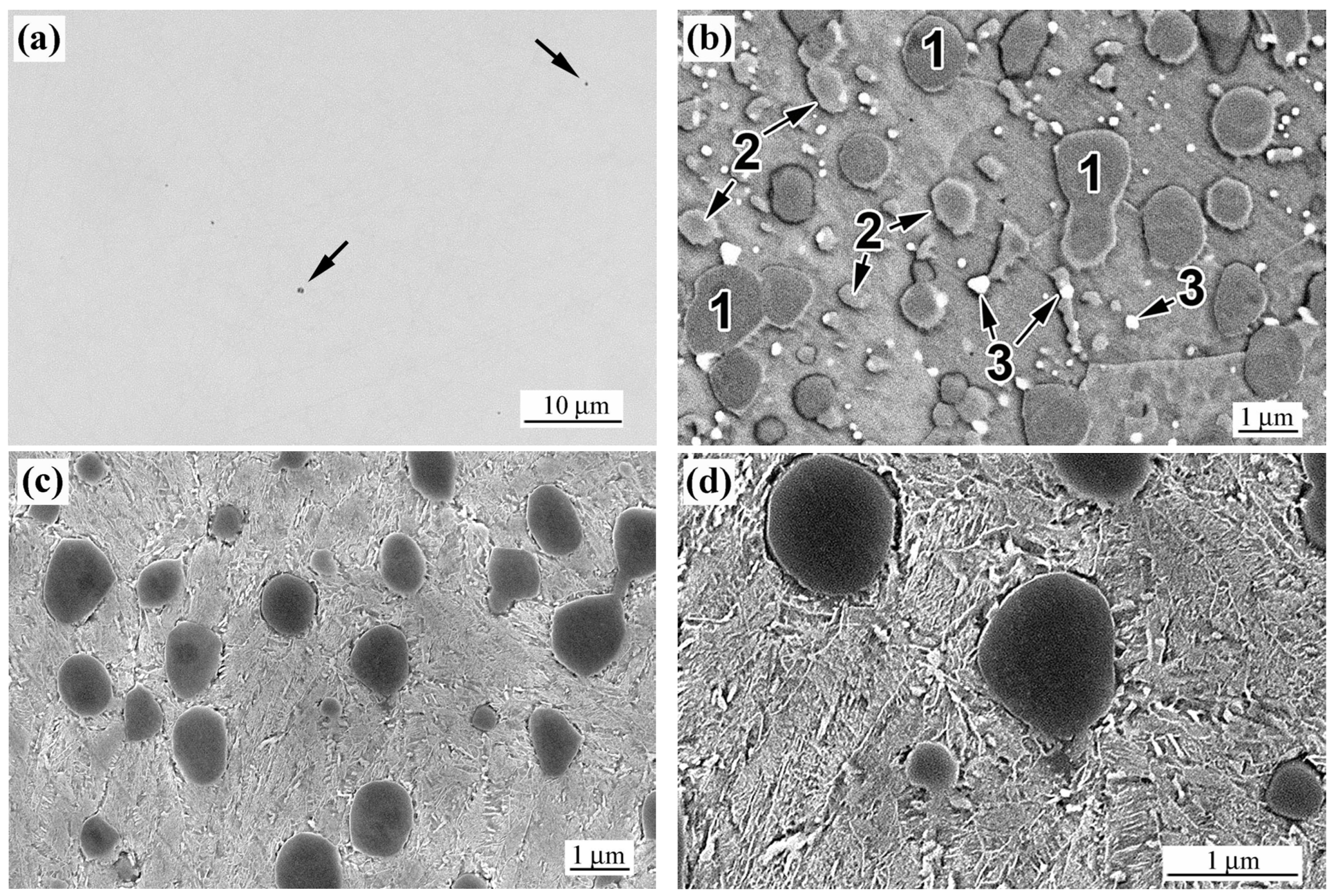
Figure 1. Microstructure of K390 steel: (a,b) in the as-received condition, and (c,d) after bulk heat treatment. ((a)—OM; (b)—SEM/BSE; (c,d)—SEM/SEI; (a)—non-etched; (bd)—etched).
Eng 06 00313 g001
Figure 2. XRD patterns of K390 steel in the as-received (AR) and bulk heat-treated (HT) conditions.
Eng 06 00313 g002
Figure 3. EDX elemental maps showing the distribution of C, V, Mo, Cr, and Fe in the as-received (AR) specimen.
Eng 06 00313 g003
Figure 4. Microstructure of the AR+L specimen. (a) Cross-sectional view with the structural layers A, B and C. (b,c) Microstructure at point 1. (d) EDX distribution of C, V, Cr and Mo at point 1. Microstructure at the points (e) 2, (f) 7, and (g) in layer C. ((a)—OM; (b,eg)—SEM/SEI; (c)—SEM/SEI/BSE; (d)—SEM/SEI/EDX).
Eng 06 00313 g004aEng 06 00313 g004b
Figure 5. XRD patterns of the AR+L and HT+L specimens.
Eng 06 00313 g005
Figure 6. Microstructure of the HT+L specimen: (a) general view of the laser-modified layer; (b) subsurface region containing oxide inclusions; (c) structureless matrix in the near-surface zone; (d) microstructure at a depth of 150 µm; (e) microstructure of the laser-modified layer at the boundary with untreated basement, featuring a martensitic matrix; (f) inward gradient of the volume fraction of the structureless matrix in AR+L and HT+L specimens. ((a)—OM; (be)—SEM/SEI).
Eng 06 00313 g006aEng 06 00313 g006b
Figure 7. Microhardness distribution across the laser-modified layer in the AR+L and HT+L specimens.
Eng 06 00313 g007
Figure 8. The results of the EBSD analysis of the specimens AR+L: (a) IPF map; (b) BC + GB maps (green lines are the HAGBs, red lines are LAGBs); (c) KAM map; (d) Phase maps.
Eng 06 00313 g008aEng 06 00313 g008b
Figure 9. The results of the EBSD analysis of the specimens HT+L: (a) IPF map; (b) BC + GB maps (green lines are the HAGBs, red lines are LAGBs); (c) KAM map; (d) Phase maps.
Eng 06 00313 g009
Figure 10. 3D views of the wear tracks on the specimens are presented for: (a) AR, (b) HT, (c) AR+L, and (d) HT+L. (e) Corresponding wear track profiles.
Eng 06 00313 g010
Figure 11. (a) Evolution of the coefficient of friction during sliding tests. (b) Volume loss and wear resistance coefficient (WRes.) of the tested alloys.
Eng 06 00313 g011
Figure 12. SEM (SE/BSE) images of the worn surfaces of the specimens: (a) AR, (b) HT, (c) AR+L, and (d) HT+L. (e) Elemental distribution of Cr, O, and Si across the tribo-layer in the HT+L specimen.
Eng 06 00313 g012
Figure 13. (a) Detailed XRD patterns of (111)FCC and (110)BCC lines. (b) Variations of the lattice parameters of α-Fe and γ-Fe, along with the carbon content in retained austenite (Cγ). (c) Variations in FWHM of the (110)BCC, (200)BCC and (211)BCC reflections. (d) Williamson–Hall plots for the studied specimens. (e) Variations in crystallite size (D) and dislocation density.
Eng 06 00313 g013
Table 1. Chemical compositions (at.%) detected by EDX in different areas of the wear tracks on AR, AR+L, and HT+L specimens. Iron was considered the balance element; carbon was excluded from the calculation.
ElementsARAR+LHT+L
Oxide FilmDeformed Area“Fresh”
Area
Oxide FilmDeformed Area“Fresh”
Area
Oxide FilmDeformed Area“Fresh”
Area
O56.810.64.750.14.15.032.927.23.4
Si5.11.11.06.21.51.18.06.81.4
V4.35.24.45.11.81.51.71.53.4
Cr1.82.33.03.34.84.12.32.93.8
Mn0.30.90.20.20.20.20.60.60.4
Mo1.01.20.81.31.00.30.70.81.2
W0.00.10.30.30.20.20.10.20.2
Fe30.778.685.633.586.487.653.760.086.2
Disclaimer/Publisher’s Note: The statements, opinions and data contained in all publications are solely those of the individual author(s) and contributor(s) and not of MDPI and/or the editor(s). MDPI and/or the editor(s) disclaim responsibility for any injury to people or property resulting from any ideas, methods, instructions or products referred to in the content.