Abstract
Carbon capture and utilization (CCU) has emerged in recent years as a promising decarbonization solution for hard-to-abate industries. Compared to carbon capture and storage (CCS), CCU aims not for the storage of carbon dioxide (CO2) but for its use in the production of synthetic fuels, such as synthetic methanol (MeOH). Synthetic MeOH is produced through CO2 hydrogenation, utilizing green hydrogen (H2). Efficient use of CO2 and H2 feedstocks is essential to maximize the carbon reduction potential and energy efficiency of the process. This study performed an optimization analysis on a small-scale, containerized, and portable CO2 hydrogenation unit with a 5 kg MeOH/h production capacity goal, focusing on carbon conversion efficiency (CCE), MeOH yield, H2 consumption, and MeOH purity. The analysis was conducted using Aspen Plus V12. A single-pass model was used first to evaluate an initial reactor design. The reactor was then re-designed according to the results of the gas hourly space velocity (GHSV). The model was then expanded to include a recycling loop and the final reactor design was validated, aiming to maximize overall efficiency. The effects of the operational parameters including the reactor inlet temperature, reactor pressure, thermal fluid temperature, and condensation temperature were examined. The model was then further expanded to include the MeOH distillation process, and the effect of the distillation temperature was examined. The final product of the analysis was a fully-defined and optimized unit, achieving an 87.97% CCE and an 84.99% MeOH yield, consuming 1.11 kg H2/h for the production of 5.01 kg MeOH/h of 99.86 wt% purity. This study can provide valuable information and guidelines for designing small-scale, containerized, and portable CO2 hydrogenation units, which can serve as alternative solutions to address issues of H2 production and transportation related to large-scale installations.
1. Introduction
In 2023, energy-related carbon dioxide (CO2) emissions reached a new high record of 37.4 Gt [1]. A significant amount of these emissions is attributed to the industrial sector. To tackle the challenge of global warming and achieve the European goals of climate neutrality by 2050, the mitigation of these emissions is essential. In that line, industries focus on adopting low CO2 solutions for their energy demands. These solutions can either focus on CO2 generation prevention, through electrification and the use of alternative green fuels such as hydrogen (H2), or the prevention of generated CO2 being released into the atmosphere.
In this second approach, carbon capture, utilization, and storage (CCUS) has gained much ground in recent years, especially for hard-to-abate industries, and is constantly promoted through new legislations and projects. In 2021, R&D investments in CCUS reached a record high, attracting 39% of funds in the EU [2]. In 2022, the CCUS industry showed an unprecedented 44% growth in capacity.
In both carbon capture and utilization (CCU) and carbon capture and storage (CCS), CO2 is captured pre-combustion, post-combustion, or during an oxy-combustion [3]. In the case of CCS, the captured CO2 is then injected into deep underground formations such as depleted oil and gas reservoirs or saline aquifers. CCU on the other hand sees the use of captured CO2 for the production of synthetic fuels such as synthetic methanol (MeOH).
CCU presents some significant benefits over CCS. For one, available storage capacity, while ample, is expendable, and as CCS continues to grow, it can be expected to drop exponentially. A more immediate challenge, however, is that storage sites can be very distant from the CO2 source, therefore requiring extensive transportation infrastructure, increasing energy requirements, costs, and the possibility of CO2 leakages. CCU has no such spatial limitations, as the production of synthetic fuels can be performed on the same site as carbon capture.
CCU is also supported by the promotion of synthetic fuels. The MeOH market is especially driven by the automotive sector, used in internal combustion in gasoline blends, hybrid fuel/electricity systems, as well as fuel cells [4]. In 2021, 11.7 Mt of MeOH was used for gasoline blending and combustion [5]. MeOH also gains ground as an alternative marine fuel abiding by the International Maritime Organization (IMO)-imposed limits of 0.5% sulfur content on marine fuels, and the overall mitigation of emissions [6]. Synthetic MeOH accounts for reductions of almost 100% in sulfur oxides, 100% in particulate matter reduction, 95% in CO2, and 80% in nitrogen oxides. In 2021, more than 20 MeOH-powered large ships were sailing the seas. In 2022, a major player of the marine sector in Denmark increased the order of 16,000 TEU MeOH-powered containerships from 8 to 12. In aviation, synthetic MeOH is gaining ground as an alternative feedstock for kerosene production.
CCU has significant CO2 reduction potential and a substantial market for its fuel products. Nevertheless, the technology faces many challenges raising questions of feasibility slowing down its promotion, especially compared to its CCS counterpart. One drawback is the lesser CO2 reduction potential. After capture, CCS direct CO2 emissions are attributed to leakages during transportation, injection, and long-term storage. These emissions are generally negligible. During CCU, however, a much higher volume of unconverted CO2 is emitted.
Another important challenge is that of high H2 consumption. Production of H2 through electrolysis requires approximately 55 kWh/kg [7]. Production through grid electricity (yellow H2) is simply unviable, both environmentally and economically, and would make CCU more of a problem than a solution. When produced through electricity from renewable energy sources (RES), production emissions are almost nullified; however, the issue of the economic feasibility of steel remains. To tackle these issues, CCU technologies aim to maximize carbon conversion efficiencies (CCE) while keeping H2 consumption at a minimum. High H2 consumption is also associated with issues of safe storage, transportation, and overall handling, supporting the idea of developing and commercializing small-scale, containerized, and portable units that can be transported to H2 production sites.
Research interest in the production of MeOH from CO2 and H2 has grown in the past decade.
VanDal and Bouallou performed simulations of a MeOH production plant from CO2 hydrogenation that utilized 88 tons of CO2/h with a yield of 0.67 tons of MeOH per ton of CO2 supplied [8]. The catalyst utilized was a commercial Cu/ZnO/Al2O3 catalyst. The results showed that it is possible to abate 1.6 tons of CO2 per ton of MeOH produced if a by-product is sold. Their work also included information about H2 production and CO2 capture.
Kiss et al. developed a novel process for MeOH synthesis by CO2 hydrogenation utilizing wet H2 from brine electrolysis and Cu/Zn/Al/Zr fibrous catalysts [9]. The process was targeted to produce 100 kton MeOH/a and was simulated in Aspen Plus software. Their investigation of several operational parameters concluded that it is possible to achieve over 95% carbon conversion overall and that higher MeOH yield is observed at higher pressures and lower GHSV.
Belloti et al. performed a feasibility study of MeOH production from H2 and CO2 considering three different capacities for MeOH production (4000, 10,000, and 50,000 ton/year) [10]. The results obtained from their analysis show a significant potential for innovative low-carbon footprint MeOH production.
Pérez-Fortes et al. designed a MeOH-CCU plant in CHEMCAD software with a production capacity of 1320 tons MeOH/day and assessed its techno-economic metrics [11]. Their analysis revealed an overall carbon conversion of 94%, while the project could become financially attractive if H2 prices decrease, if MeOH prices increase, or if there is a generous revenue from CO2 utilization.
Atsonios et al. investigated the production of MeOH through CO2 hydrogenation in large-scale applications, focusing on CO2 derived from intensive carbon emission industries such as power plants, cement plants, and steel industries [12]. H2 was produced by water electrolysis. Their study provided insights into H2 production and included a techno-economic evaluation highlighting the critical importance of H2 cost.
Therefore, several studies have been conducted assessing the production of MeOH through CO2 hydrogenation, and evaluating various reactor types and catalysts. However, the majority of the studies focus on large-scale or laboratory-scale MeOH production, disregarding the possibilities of small-scale, decentralized MeOH production.
CO2 hydrogenation units typically have a standard structure and layout, regardless of the scale. The operational parameters (pressures and temperatures) are also generally in the same ranges. Therefore, when designing a unit and examining its performance, normalized, size-independent parameters such as the gas hourly space velocity (GHSV) and the H2:CO2 ratio in the feed are considered. While the realization of the designed units may be significantly affected by the scale, mostly in terms of auxiliary components and handling of larger volumes of reactants, in the scope of an optimization process and simulations, a study’s framework/methodology is relatively the same, differing only on the initial dimensioning and specifications of the components. Therefore, an optimization analysis can be easily modified for an up-scaled or down-scaled unit, keeping the normalized parameters within the same ranges and re-examining the effect of operational parameters, which should be relatively scale-independent.
This study performs an optimization analysis on a CO2 hydrogenation unit of a 5 kg MeOH/h production capacity goal, developed for such applications. CO2 captured and bottled in existing carbon capture infrastructure and H2 produced from existing water electrolysis units are supplied to the CO2 hydrogenation unit. The analysis focused on CCE, MeOH yield, H2 consumption, and MeOH purity. Simulations were conducted using Aspen Plus V12. An initial reactor design was hypothesized and evaluated based on the GHSV, through a simplified single-pass model. The reactor was re-designed accordingly and validated through an expanded model which included a recycling loop to increase the overall efficiency. After concluding the reactor design, the effect of operational parameters including reactor temperature and pressure, thermal fluid temperature, and condensation temperature were examined. The model was then expanded to include MeOH distillation and the effect of distillation temperature was examined. The final product of the analysis was a well-defined and optimized unit of 5 kg/h MeOH production. This study can provide valuable information and guidelines for designing small-scale, containerized, and portable CO2 hydrogenation units, which can serve as alternative solutions to address the H2 handling issues of large-scale installations.
2. The CO2 Hydrogenation Unit
2.1. System Layout
CO2 hydrogenation was performed as follows. Bottled CO2 and H2 from water electrolysis were introduced to the unit, pressurized to a designated reaction pressure, and then mixed. The unified flow was then pre-heated and entered the reactor where CO2 hydrogenation to MeOH occurs, typically at temperatures of 210–270 °C and high pressures, 50–100 bar [8].
The flow exiting the reactor, consisting of produced MeOH, by-product carbon monoxide (CO) and water, and unreacted CO2 and H2, passed through a condenser where only MeOH and water were condensed. Condensation typically takes place at ~35 °C to allow for the condensation of only MeOH and water.
The bi-phasic mixture was then introduced to a flash separator where liquids were separated from the gases. The gases were recompressed to the reaction pressure, mixed with the fresh CO2 and H2 feeds, and recycled to the reactor, to minimize the release of CO2 and valuable but also hazardous H2 in the atmosphere, increasing the overall efficiency. Before recompression, a small percentage of the gases exiting the flash separator was purged or flared to prevent the accumulation of byproducts.
The MeOH/water liquid stream exiting the separator was decompressed to near atmospheric pressure and could then pass through a second flash separator to further remove gaseous residues and increase MeOH purity (fuel-grade purity requirement was 99.85 wt%, with water impurities lower than 0.1 wt%) [13]. The gases exiting the second flash tank were rejected, as their recycling would entail high recompression costs.
The liquid stream (crude MeOH) was then pre-heated and introduced to the distillation column where MeOH was separated from water and the remaining light components. The distillate product was pure MeOH (99.85 wt%), while the bottom product was mainly water (~99 wt%). The small overhead vapor stream was rejected or flared. MeOH distillation took place at 70–100 °C, while the reflux drum temperature was set at 60 °C. The distiller was also equipped with a reboiler with a base temperature of 50 °C. The CO2 hydrogenation unit is presented in Figure 1.
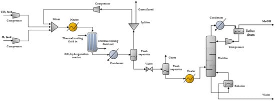
Figure 1.
CO2 hydrogenation unit flowsheet.
2.2. Reactor Design
CO2 hydrogenation is a highly exothermic reaction; thus, heat removal is a necessary feature for CO2 hydrogenation reactors. Multi-tubular packed bed catalytic reactors are commonly used for these applications. These reactors consist of multiple parallel tubes where the catalyst is placed and the reaction occurs. Commonly used catalysts are mixes of Cu or CuO, ZnO, and Al2O3. Water or diathermic oil flows between the tubes (reactor shell) to absorb excess heat and can then be utilized in the pre-heating of the reactants, before being cooled and reintroduced to the reactor’s shell. The same fluid can also operate as a thermal fluid, especially during the system’s startup, to bring the reactor to the desired reaction temperature. After startup, heat will begin to produce from the reactions and the fluid must shift to its cooling function. The design of a conventional multi-tubular catalytic reactor is shown in Figure 2.
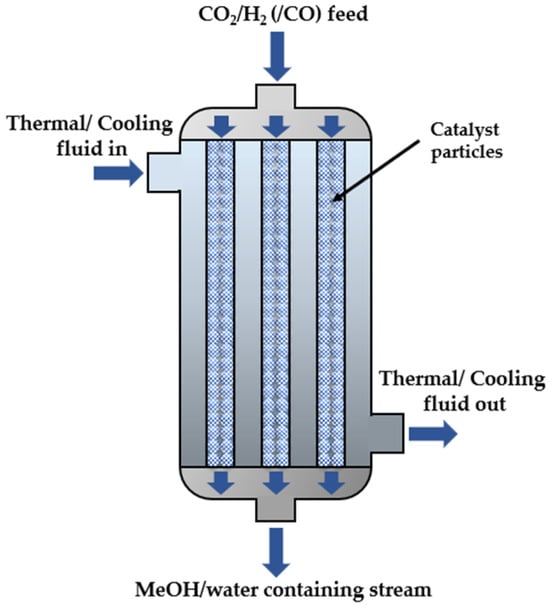
Figure 2.
Design of multi-tubular catalytic reactor.
3. Modeling Framework
3.1. Optimization Analysis Methodology
The optimization analysis was conducted through simulations performed with Aspen Plus V12. A MeOH production capacity of 5 kg/h was set for all simulations, around which the optimization was performed. The analysis was conducted through seven steps:
Step 1: The multi-tubular reactor and occurring reactions are modeled in the Aspen Plus environment.
Step 2: An initial reactor design is hypothesized and evaluated based on the GHSV, through a simplified single-pass model, for typical operational parameters.
Step 3: The reactor is re-designed and evaluated with the same single-pass model and operational parameters, according to the results on GHSV. The results are also used to approximate the required volume of reactants in the reactor’s inlet, which is used to estimate the fresh CO2 and H2 feed when incorporating a recycling loop.
Step 4: The model is expanded to include a recycling loop to improve overall efficiency and the re-designed reactor is validated by examining the CCE, MeOH yield, and H2 consumption compared to other designs.
Step 5: The effect of operational parameters on the CCE, MeOH yield, and H2 consumption is examined with the expanded model. The examined parameters include reactor inlet temperature and reactor pressure, thermal fluid temperature, and condensation temperature.
Step 6: After defining the optimal operational parameters, the model is further expanded to include the distillation process, and the effect of distillation temperature to the MeOH purity and overall performance is examined.
Step 7: The optimized design and operational parameters of the overall unit are defined, as the final product of the analysis.
CCEReactor refers to the CCE of the reactor itself while CCEUnit refers to the CCE of the overall unit, and are defined as follows:
where
is the CO2 mole flow at the reactor’s inlet;
is the CO2 mole flow at the reactor’s outlet;
is the fresh CO2 mole flow; and
is the total CO2 mole flow exiting the unit.
The MeOH yield is defined as follows:
The MeOH yield can be defined for both the reactor and the unit, the two differing due to the fraction of produced MeOH that cannot be collected in the end of the process. This, however, is typically a very small percentage due to unavoidable inefficiencies in condensation, separation, and distillation processes. The difference among the two is negligible and does not provide significant information for the unit’s performance. For the purposes of this study, the reactor’s MeOH yield will not be examined, and MeOH yield will henceforth always refer to overall unit.
3.2. Reactor and Reactions Modeling
3.2.1. Catalytic Reactor Modeling
The reactor was simulated through the Aspen Plus RPlug module for catalytic reactors. Reaction rates are significantly affected by the catalyst of choice. For the particular analysis, the commercial MK-121 catalyst was considered, the specifications for which are summarized in Table 1.

Table 1.
Specifications of commercial MK-121 catalyst [14].
Catalyst geometry is essential for calculating the pressure drop in the reactor through the Ergun Equation:
where ΔP is the pressure drop (Pa); L is the bed height (reactor’s active height) (m); μ is the fluid viscosity, (kg/ms); ρ is the density of the fluid, (kg/m3); ε is the mean voidage; U is the fluid superficial velocity (m/s); and dp is the particle diameter (m).
3.2.2. Reactions Modeling Kinetics
During the CO2 hydrogenation process, mainly three reversible reactions take place, listed in Table 2. The system is described through the reactions of CO2 hydrogenation, where CO2 reacts with H2 to produce MeOH and water, reverse water gas shift (RWGS) reaction, where CO2 reacts with H2 for the production of CO and water, and CO hydrogenation, where CO reacts with H2 to produce MeOH. The overall process is exothermic. All three reactions are not independent, and the conversion can be described based on reactions 1 and 2 according to Van-Dal and Bouallou [8].

Table 2.
Reactions during CO2 hydrogenation process.
The reacting phase is vapor, and the basis of reaction rate is calculated according to the catalyst weight for all reactions. The kinetic model applied in this paper is based on the work of Vanden Bussche and Froment, while the thermodynamic equilibrium constants are taken from Graaf et al. [15,16]. Reaction kinetics were introduced to ASPEN Plus software through the generalized Langmuir–Hinshelwood–Hougen–Watson (LHHW) kinetic model by which the rate of reaction i (ri) is expressed as follows:
The rates of reaction,
with respect to component
are given in the following equations:
In the above equations,
represents the partial pressure of component
. The kinetic factor is calculated by the Arrhenius equation:
When the reference temperature (T0) is unspecified, pre-exponential factor Ai is calculated as:
The thermodynamic equilibrium constants are given in the following equations:
3.3. Single-Pass Model
Simulations began with a simplified, single-pass model focusing on the optimization of the reactor’s design. Specifically, the single-pass model was used to evaluate the GHSV of a hypothesized initial design and re-design the reactor accordingly. Therefore, the single-pass model did not include a recycling loop or the components after the first flash separator, namely the second flash separator and the distiller. The model developed in Aspen Plus is shown in Figure 3.
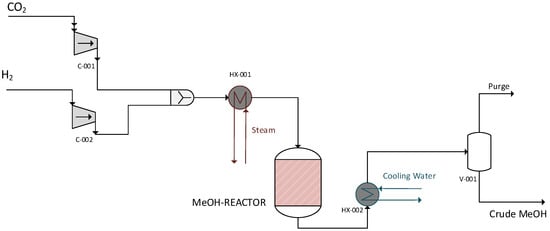
Figure 3.
Single-pass model.
3.4. Model with Recycling Loop
After re-designing the reactor, the model was expanded to include a recycling loop. This model was used to (1) validate the reactor’ design and (2) evaluate the effect of operational parameters, i.e., reactor temperature and pressure, thermal fluid temperature, and condensation temperature on the CCE, MeOH yield, and H2 consumption. For this, unreacted gas, instead of being flared, is recycled back to the reactor after being compressed up to the operating pressure of the reactor. This expanded model is presented in Figure 4.
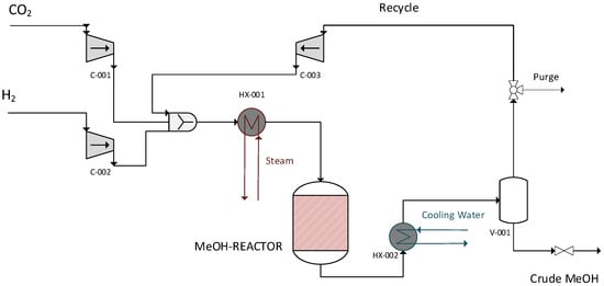
Figure 4.
Model with recycling loop.
3.5. Model with Distillation—Complete Model
After defining the optimal operational parameters, the model was expanded to include the second separator and the distillation column, in order to evaluate the effect of distillation temperature on the MeOH purity and the overall performance. The final complete model is presented in Figure 5.
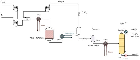
Figure 5.
Model with distillation—complete model.
4. Results
4.1. Simulations with Single-Pass Model—Optimizing Reactor Design
In the first step, an initial reactor design is hypothesized, based on information from the literature for the MeOH yield and GHSV. The dimensions of this initial design are shown in Table 3.

Table 3.
Initial reaction design.
Simulations were conducted for the operational parameters summarized in Table 4, and the reactor’s design was evaluated based on the GHSV. The heat transfer between the reactants in the tubes and the boiling water flowing between the tubes was estimated by correlating heat transfer coefficients found in the literature [17].

Table 4.
Initial operational parameters.
The key results of the single-pass simulations with the initial reactor design are summarized in Table 5. For the single-pass simulations
is the MeOH mole flow in the crude stream exiting the separator.

Table 5.
Key results of single-pass simulations for the initial reactor design.
Simulations showed that the GHSV for the initial design was significantly lower than the typical values for the industrial operation of MeOH production reactors of 9000–15,000 h−1 [14]. The velocity in the reactor was as low as 0.011 m/s, resulting in a very high residence time. To achieve more optimal velocity and residence time, the reactor’s active volume should be reduced. The easiest modification was reducing the number of tubes. The number of tubes was reduced to 14. In addition, the bed height was slightly reduced, from 1.2 m to 1 m. The re-designed reactor’s dimensions are summarized in Table 6.

Table 6.
Re-designed reactor.
Simulations were conducted for the re-designed reactor for the same operational parameters (Table 4). The key results for the re-designed reactor are summarized in Table 7.

Table 7.
Key results of single-pass simulations for the re-designed reactor.
GHSV was significantly improved for the new design. However, the reduced residence time resulted in lower CCE. At the same time, the energy requirements for the entire system increased. Nevertheless, even in the case of very high residence times, such as for the initial design, CCEUnit is lower than 29%, which is significantly lower compared to the respective literature [8,18,19].
Generally, for the single-pass model, CO2 and H2 consumption for the set production capacity was considerably high. Additionally, a large volume of gases is flared, containing approximately 75 mol% H2. Notably, 75–81 wt.% of the gases introduced to the unit are flared rather than utilized, resulting in system losses.
4.2. Simulations with Recycling Loop—Validating Reactor Design
A recycling loop was added to the unit to increase efficiency by lowering the quantity of CO2 and H2 lost and the amount of feedstock that is required. To determine the optimal quantity of unreacted gases to be recycled back to the reactor, an investigation was conducted on the effect of the percentage of unreacted gases recycled on carbon conversion, MeOH yield, and H2 consumption for the given production (5 kg MeOH/h).
The operational parameters were kept the same (Table 4). The results of the effect of the percentage of unreacted gases recycled on the CCEUnit are shown in Figure 6.
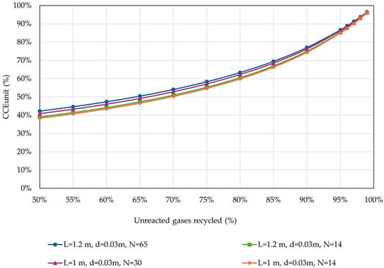
Figure 6.
CCEUnit in relation to the percentage of unreacted gases recycled back to the reactor, for different reactor designs (operational parameters as listed in Table 4).
CCEUnit is significantly affected by the percentage of unreacted gases recycled. The results showed that the CCEUnit is significantly improved at a higher percentage of recycled gases for all investigated reactor configurations. Moreover, in the presence of a recycling loop, the reactor’s dimensions do not significantly affect the CCEUnit, especially for higher percentages of gases recycled.
Figure 7 presents the results of the effect of the percentage of unreacted gases recycled on MeOH yield.
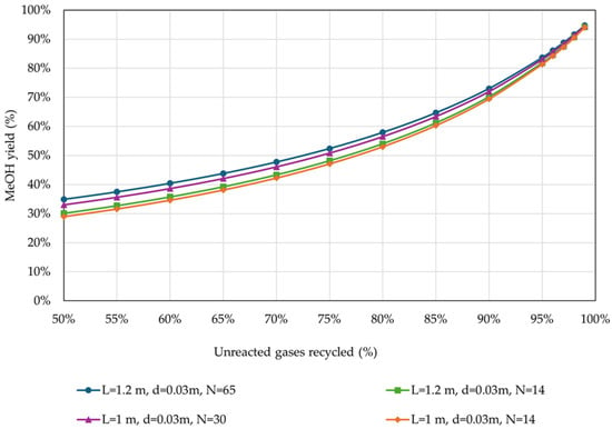
Figure 7.
MeOH yield in relation to the percentage of unreacted gases recycled back to the reactor, for different reactor designs (operational parameters as listed in Table 4).
As expected, MeOH yield presented similar trends to CCEUnit. Figure 8 presents the effect of the percentage of unreacted gases recycled on H2 consumption, for the examined reactor designs.
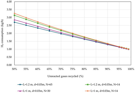
Figure 8.
H2 consumption in relation to the percentage of unreacted gases recycled back to the reactor, for different reactor designs (operational parameters as listed in Table 4).
The results showed that H2 consumption is significantly affected by the reactor’s dimensions only in the case of the low percentage of unreacted gases recycled. For percentages higher than 90%, these differences can be considered negligible. Specifically, the H2 consumption for the production of 5 kg MeOH/h is approximately 2.5 times higher for recycling percentage as low as 50% of the unreacted gases, compared to the cases with 95% recycling percentage.
An analysis of the energy requirements in relation to the recycling rate is presented below. Figure 9 depicts the impact of the percentage of unreacted gases recycled on the heat duty of the process, for the examined reactor designs. It is important to note that the reboiler duty is not included in this heat duty analysis, as it is examined separately. Consequently, only the duty requirement at the reactor inlet and the distillation inlet are presented in this figure.
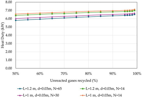
Figure 9.
Heat duty in relation to the percentage of unreacted gases recycled back to the reactor, for different reactor designs (operational parameters as listed in Table 4).
It can be observed that the heat duty increases by approximately 1 kW or 0.2 kWh/kg MeOH with the increase in the recycling rate of the unreacted gases, for all investigated reactor designs. Such an increase is expected as with a higher recycling rate, more cold unreacted gases return to the reactor inlet, increasing the reactor inlet heat duty. Additionally, due to the different heat capacities of the crude stream, there is a higher distillation heat requirement.
Figure 10 presents the results of the effect of the percentage of unreacted gases recycled on the cooling duty of the reactor’s effluent.
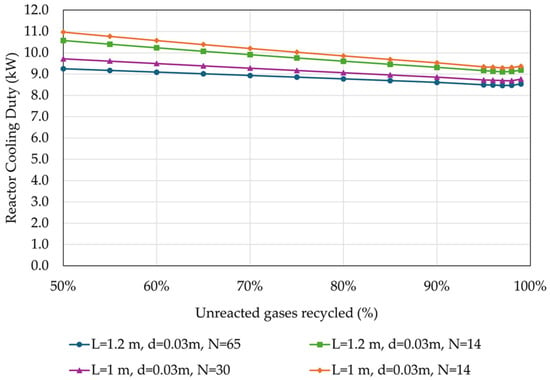
Figure 10.
Cooling duty of the reactor’s effluent in relation to the percentage of unreacted gases recycled back to the reactor, for different reactor designs (operational parameters as listed in Table 4).
The cooling duty at the reactor’s effluent is marginally decreased with the increase in the of the recycling rate of the unreacted gases by less than 1 kW (<0.20 kWh/kg MeOH) for all investigated reactor designs due to the different heat capacities of the stream.
In Figure 11 the results of the effect of the percentage of unreacted gases recycled on the electricity requirement of the process are depicted. These requirements encompass the electricity used to operate the compressors of the feed streams, specifically fresh CO2 and fresh H2 streams.
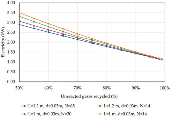
Figure 11.
Electricity requirement of the overall process in relation to the percentage of unreacted gases recycled back to the reactor, for different reactor designs (operational parameters as listed in Table 4).
As expected, the electricity requirement decreases with the increase in the recycling rate of the unreacted gases by almost 2 kW or more (0.4 kWh/kgMeOH) for all investigated reactor designs. This reduction is attributed to the lower demand for fresh H2 and consequently fresh CO2, as seen in Figure 8.
Figure 12 shows the variation in the reboiler duty with respect to the recycling rate of the unreacted gases.
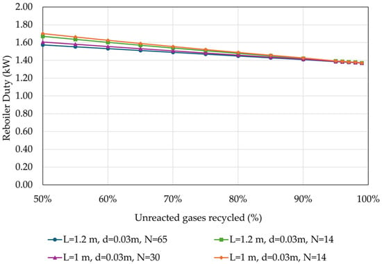
Figure 12.
Reboiler duty in relation to the percentage of unreacted gases recycled back to the reactor, for different reactor designs (operational parameters as listed in Table 4).
The reboiler duty decreases slightly, by less than 0.4 kW or 0.08 kWh/kg MeOH, with the increase in the recycling rate of the unreacted gases. This variation is attributed to the slightly higher percentage of MeOH in the crude, resulting in lower heat demand for crude distillation.
The above findings suggest that a recycling rate greater than 95% should be implemented to achieve optimal results. Furthermore, since no discernible differences were found between the reactor designs, the smaller reactor was selected for further investigation.
4.3. Simulations with Recycling Loop—Optimizing Operational Parameters
After validating the reactor’s design, the next step was examining the effect of the system’s operational parameters on its overall performance. For all simulations, the percentage of gases flared was fixed at 4%, which corresponds to 96% recycling of unreacted gases.
For the defined design parameters (Table 6), a thorough analysis of the thermodynamic performance of the process is conducted to determine the optimized operating parameters of the overall MeOH production system. The varying parameters are based on information from MeOH reactor operators and catalyst providers that limit the reactor temperatures from 190–210 °C to 300–315 °C. The first step of the analysis included the examination of the effect of the reactor pressure and thermal fluid temperature on the CCEUnit, MeOH yield, and H2 consumption. Figure 13 presents the effect of the reactor pressure and thermal fluid temperature on the CCEUnit.
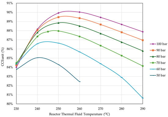
Figure 13.
Effect of reactor pressure and thermal fluid temperature on CCEUnit (percentage of unreacted gas flared = 4%, reactor inlet temperature = 210 °C, rest of operational parameters as listed in Table 4).
The results showed that increasing the pressure improves the CCE. Thermal fluid temperature on the other hand presents an optimal range from 240 °C to 260 °C, depending on the pressure. The results also showed that from 70 to 100 bar, the CCEUnit increased less than 3%; therefore, the risk of overpressure from the 30-bar jump is unnecessary, and a pressure limit of 70 bar was set. At 70 bar, the optimal thermal fluid temperature is 250 °C.
Figure 14 presents the effect of thermal fluid temperature and reactor pressure on the MeOH yield.
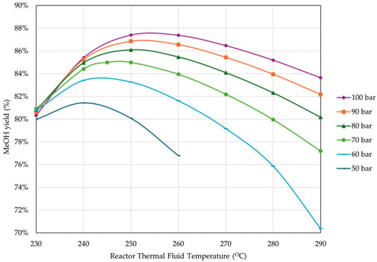
Figure 14.
Effect of reactor pressure and thermal fluid temperature on MeOH yield (percentage of unreacted gas flared = 4%, reactor inlet temperature = 210 °C, rest of operational parameters as listed in Table 4).
As expected, MeOH yield presented a similar behavior to CCE. Figure 15 shows the effect of thermal fluid temperature and reactor pressure on H2 consumption.
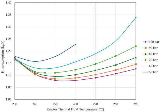
Figure 15.
Effect of thermal fluid temperature and reactor pressure on H2 consumption (percentage of unreacted gas flared = 4%, reactor inlet temperature = 210 °C, rest of operational parameters as listed in Table 4).
As expected, H2 consumption has the exact opposite behavior as CCE, specifically, consumption decreases with the increase in pressure. Moreover, an optimal thermal fluid temperature is observed for each pressure condition. Similar to CCEUnit, the differences in H2 consumption are minor above 70 bar.
In the above investigation, operational pressures as low as 50 bar combined with thermal fluid temperatures exceeding 260 °C resulted in a significant rise in reactor pressure drop. Therefore, results for these operating conditions are not plotted.
The analysis proceeded with the examination of the effect of the reactor’s inlet temperature (the pre-heating of the reactor feed) while maintaining a fixed thermal fluid temperature at 250 °C and fixed pressure at 70 bar. The results are presented in Figure 16.
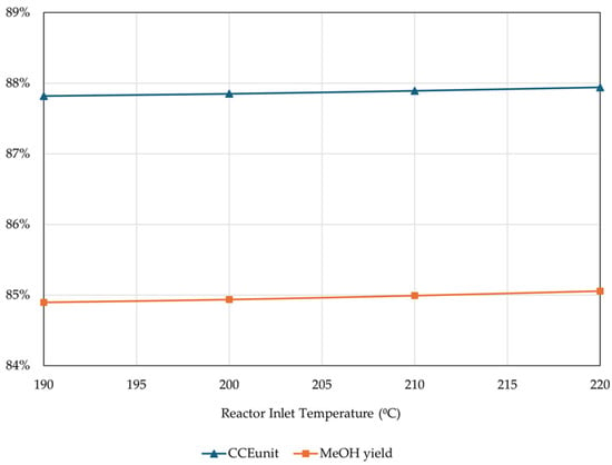
Figure 16.
Effect of reactor inlet temperature on CCEUnit and MeOH yield (percentage of unreacted gas flared = 4%, rest of operational parameters as listed in Table 4).
The results showed that in the presence of a thermal fluid, CCEUnit and MeOH yields are practically unaffected by the reactor inlet temperature, and it is therefore optimal to go with lower temperatures to minimize the pre-heating duties. However, not all MeOH catalysts can be activated at temperatures below 210 °C. Thus, an inlet temperature of 210 °C was chosen and fixed for the rest of the simulations.
Another factor investigated was the effect of condensation temperature on the unit’s performance, keeping the rest of the parameters fixed. The effect of condensation temperature on the CCEUnit and MeOH yield is presented in Figure 17.
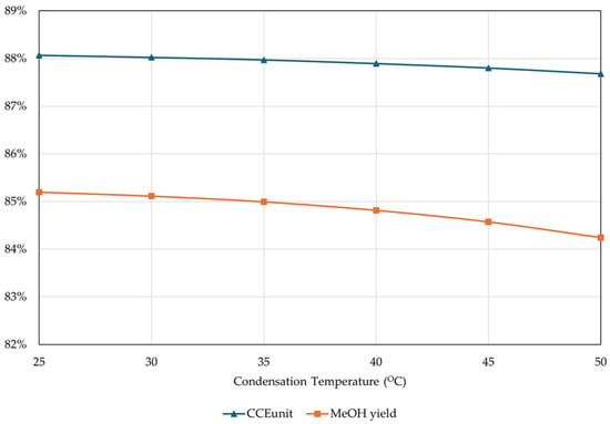
Figure 17.
Effect of condensation temperature on CCEUnit and MeOH yield (percentage of unreacted gas flared = 4%, rest of operational parameters as listed in Table 4).
The results showed that when ranging from 25–50 °C, condensation temperature does not significantly affect the CCEUnit and MeOH yield (the difference is less than 1%). This indicates that condensation temperature could be kept at maximum to reduce the cooling duties. However, higher condensation temperatures result in slightly higher H2 consumption. In order to evaluate the optimal condensation temperature, the total energy requirements, including all auxiliaries, H2 production, and carbon capture were examined and presented in Figure 18. An average of 55 kWh/kg was considered for H2 production through water electrolysis, while an average of 1.2 kWh/kg CO2 was considered for the post-carbon capture unit. The recoverable heat from the suggested MeOH production system was also considered, to examine the theoretically possible lowest energy consumption.
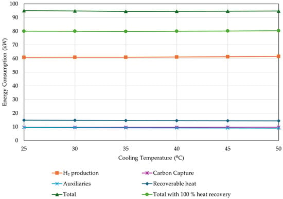
Figure 18.
Effect of condensation temperature on energy consumption (percentage of unreacted gas flared = 4%, rest of operational parameters as listed in Table 4).
The results showed that total energy consumption is not significantly affected by the condensation temperature. For this study, a typical condensation temperature of 35 °C was chosen and fixed for the rest of the simulations.
Based on the results obtained from the above analysis, the final operational parameters suggested are summarized in Table 8.

Table 8.
Optimized operational parameters.
4.4. Simulations with Complete Model—Optimizing Distillation Temperature
After defining the optimal parameters to maximize CCEUnit and minimize H2 consumption, the next step is examining the optimal parameters for efficient MeOH distillation. Distillation typically takes place at near atmospheric pressure. Distillation temperature on the other hand can vary and significantly affect MeOH purity. The effect of the distillation temperature on CCEUnit, MeOH yield, and MeOH purity is presented in Figure 19.
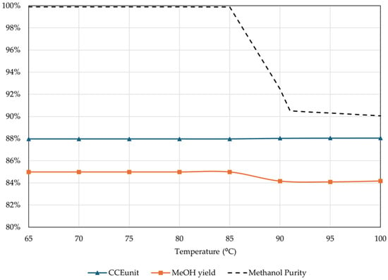
Figure 19.
Effect of distillation temperature on CCEUnit, MeOH yield, and purity (percentage of unreacted gas flared = 4%, reactor inlet temperature = 210 °C, thermal fluid temperature = 250 °C, rest of operational parameters as listed in Table 4).
The results showed that increasing the distillation temperature above 85 °C significantly reduced the MeOH purity. At 100 °C, MeOH purity can be as low as 90 wt.%, significantly lower than the desired fuel-grade purity of 99.85 wt.%. The drop in MeOH purity does not allow for higher temperatures. However, higher temperatures at the inlet of the distillation column would lead to lower reboiler duties. These temperatures can be efficiently achieved by using a heat exchanger between the reactor’s product stream and the distillation inlet stream, which not only raises the distillation temperature, reducing the heating requirements of the entire process, but also reduces the cooling requirements for the reactor’s effluent. Therefore, for this study, the highest possible temperature, without reducing MeOH purity, was selected as 85 °C.
4.5. Final Unit Specification
Considering the results of the optimization analysis, the final specifications and performance parameters of the unit are summarized in Table 9.

Table 9.
Optimized CO2 hydrogenation unit specifications.
The final unit achieved an 87.97% CCEUnit and an 84.99% MeOH yield, consuming 0.22 kg H2/kg MeOH and 1.61 kg CO2/kg MeOH. An efficient, large-scale MeOH production process demonstrated in previous research achieved a MeOH yield as high as 99.78%, while consuming 0.19 kg H2/kg MeOH and 1.36 kg CO2/kg MeOH, resulting in more efficient MeOH production compared to the proposed solution [9]. Several studies on MeOH production through CO2 hydrogenation have shown that high carbon conversion (93–100%) can be achieved with CO2 consumption ranging from 1.2 to 1.6 kg CO2/kg MeOH. However, other studies demonstrate less efficient MeOH production compared to the proposed system [20]. The energy demands of the suggested process are substantial, with electricity requirements reaching 0.25 kWel/kg MeOH, heating requirements resulting in 1.68 kWth/kg MeOH, and cooling requirements amounting to 2.60 kW/kg MeOH. Energy consumption for MeOH production from CO2 and H2 varies widely in literature, with several studies considering heat integration within the process or utilizing surplus heat produced to cover the heating needs of connected units such as a carbon capture unit [8,21].
5. Discussion
MeOH demand in Europe reached 11.3 million tons in 2023 and is expected to grow with a 3.96% compound annual growth rate (CAGR) until 2034 [22]. Approximately 15% of MeOH was used as fuel in gasoline blends in 2023, with the percentage estimated to be 16% by 2030. Nevertheless, green MeOH demand vastly exceeds the supply [23].
CO2 hydrogenation is considered the technology with the greatest potential for MeOH production [4]. It is already at a technology readiness level (TRL) of eight with numerous production plants around the world [24]. In 2022, the largest CO2 hydrogenation plant to date started production in China, with a production capacity of 110,000 tons of MeOH [25]. Nevertheless, the commercialization of large-scale plants still faces significant challenges, many of which are specifically attributed to high H2 consumption.
Many studies have highlighted that H2 production is environmentally sustainable only when clean energy sources are used, such as electricity from RES (green H2). However, direct use of electrical energy is in most cases a more efficient option than its conversion and storage in energy carriers. In other words, green H2 is typically produced using the electricity surpluses of RES parks supporting other infrastructures, as dedicating RES parks specifically to support green H2 production plants can be an inefficient use of RES potential. Considering the high electricity demands of H2 production are covered by a fraction of the RES park’s output, large-scale production needs to be supported by parks of very high capacities, which can be difficult to come by.
H2 handling is another significant issue, especially for large-scale installations. Higher H2 production exacerbates nearly every single safety issue, the extent of safety infrastructure required, the difficulty of monitoring, the probability of misuse of large-scale equipment, and the probability of leakages, to name a few. In the case of a failure, the severity of the event is directly proportional to the plant’s size. These safety issues are significantly reduced with the plant ‘size. H2 transportation is also an issue, thus use close to its production site is considered a safer option.
The solution can be found in small-scale, localized H2 production facilities powered by the energy surplus of small-scale RES parks of off-grid and net-zero energy districts. This solution pairs well with the idea of small-scale containerized and portable CO2 hydrogenation units, transported to said localized facilities. The concept of small-scale CO2 hydrogenation units has already been examined by technology providers and manufacturers [26].
In order to promote this concept, practical issues related to the unit’s scale must be addressed. One such issue is the coupling with carbon capture units, which are generally large-scale installations targeted towards large-scale industries for the capture of tons of CO2 per hour. While bottling captured CO2 and using it in retrofitted and controlled flows is a valid option, CO2 production highly exceeding CO2 consumption is a significant handling issue. In that sense, the development of small-scale carbon capture units can promote the commercialization of both technologies, and their use in more applications than only large-scale industries.
Nevertheless, the advantages of small-scale CO2 hydrogenation units outweigh the disadvantages, especially in terms of simplicity of operation, which can be fully electrified. For example, small-scale units can operate with small compressors (<2 kW) and electric heaters/reboilers, which on larger applications may be fuel-driven, adding to the unit’s complexity. Containerized MeOH production, however, has yet to be commercialized; nevertheless, significant research has been conducted by numerous European projects [27,28].
6. Conclusions
Optimizing the performance of CCU technologies is key in order to establish them as viable decarbonization solutions, especially compared to their CCS counterparts. This study performed an optimization analysis on a containerized and portable CO2 hydrogenation unit with a 5 kg/h MeOH production capacity. The analysis focused on the key performance indicators of CCE, MeOH yield, H2 consumption, and MeOH purity.
The analysis was realized in seven steps. In the first step, the multi-tubular catalytic reactor and occurring reactions were modeled in the Aspen Plus software. Step 2 was hypothesizing and evaluating an initial reactor design based on the GHSV, through a simplified single-pass model. In step 3, the reactor is re-designed and evaluated with the same single-pass model and operational parameters, according to the results on GHSV. Step 4 was expanding the model to include a recycling loop and validating the re-design with the new model. Step 5 was the examination of the effect of operational parameters in the unit’s performance and concluding on the optimal performance. Step 6 was expanding the model to include the distillation process (complete model) and examining the effect of distillation temperature on the unit’s performance. Step 7 was the definition of all specifications of the optimized unit, as the final product of the analysis.
The analysis conclusions are summarized as follows: (1) A final design of 1 m bed height, 0.03 m tube inner diameter, and 14 tubes was considered optimal for a 5 kg/h MeOH production. (2) In the presence of thermal fluid, the reactor’s inlet temperature does not significantly affect the unit’s performance; thus, a relatively low inlet temperature of 210 °C was considered optimal to reduce pre-heating requirements. (3) Increasing the reactor’s pressure significantly improved the overall performance. For all examined reactor pressures, the performance peaked at a certain thermal fluid temperature. A 70-bar reactor pressure and 250 °C thermal fluid temperature were decided, to avoid overpressure without reducing the unit’s efficiency significantly. (4) The condensation temperature of the reactor’s effluent did not significantly affect the system performance, so a typical 35 °C temperature was selected. (5) Increasing the distillation temperature significantly reduced the MeOH purity after 85 °C, which was the temperature chosen.
The final unit designed achieved an 87.97% CCEUnit and an 84.99% MeOH yield, consuming 1.11 kg H2/h to produce 5.01 kg MeOH/h of 99.86 wt% purity. The unit layout and reactor design proposed are fitting for a containerized solution, giving ample space for components typically placed above (i.e., pre-heater) or below (i.e., condenser and separators) the reactor, without exceeding the dimensions or the height limits of flat-rack containers (reactor is placed vertically in the unit). This study can provide valuable information and guidelines for designing small-scale, containerized, and portable CO2 hydrogenation units, which can serve as alternative solutions to address issues of H2 production and transportation related to large-scale installations.
Author Contributions
Conceptualization, A.P.; methodology, V.K., S.K. (Sotiris Kottaridis), and C.P.; software, V.K. and S.K. (Sotirios Karellas); validation, A.P., C.P. and S.K. (Sotirios Karellas); formal analysis, S.K. (Sotirios Karellas) and V.K.; investigation, V.K. and S.K. (Sotiris Kottaridis); writing—original draft preparation, V.K. and S.K. (Sotiris Kottaridis); writing—review and editing, C.P.; visualization, V.K. and S.K. (Sotiris Kottaridis); supervision, A.P. and S.K. (Sotirios Karellas). All authors have read and agreed to the published version of the manuscript.
Funding
This research has received funding from the European Union’s Horizon Europe research and innovation program under a grant agreement with the number 101058696, project HEPHAESTUS.
Institutional Review Board Statement
Not applicable.
Informed Consent Statement
Not applicable.
Data Availability Statement
All data sources used are cited and all data produced are reported in the manuscript.
Conflicts of Interest
The authors declare no conflict of interest.
References
- IEA. CO2 Emissions in 2023; IEA: France, Paris, 2024. Available online: https://www.iea.org/reports/co2-emissions-in-2023 (accessed on 29 May 2024).
- European Commission; Joint Research Centre; Itul, A.; Diaz Rincon, A.; Eulaerts, O.D.; Georgakaki, A.; Grabowska, M.; Kapetaki, Z.; Ince, E.; Letout, S.; et al. Clean Energy Technology Observatory, Carbon Capture Utilisation and Storage in the European Union—Status Report on Technology Development, Trends, Value Chains and Markets—2022; Publications Office of the European Union: Luxembourg, 2023; Available online: https://data.europa.eu/doi/10.2760/882666 (accessed on 29 May 2024).
- Chowdhury, F.A.; Okabe, H.; Yamada, H.; Onoda, M.; Fujioka, Y. Synthesis and selection of hindered new amine absorbents for CO2 capture. Energy Procedia 2011, 4, 201–208. [Google Scholar] [CrossRef]
- Renewable Carbon News, Renewable Methanol Market—Industry Analysis, Market Size, Share, Trends, Application Analysis, Growth And Forecast 2022–2027. 2022. Available online: https://renewable-carbon.eu/news/renewable-methanol-market-industry-analysis-market-size-share-trends-application-analysis-growth-and-forecast-2022-2027/ (accessed on 29 May 2024).
- Distribution of Methanol Demand Worldwide in 2020, by Region. Available online: https://www.statista.com/statistics/1323612/distribution-of-methanol-demand-worldwide-by-region/ (accessed on 30 May 2024).
- IRENA. Navigating to a Renewable Future: Solutions for Decarbonising Shipping, Preliminary Findings; International Renewable Energy Agency: Abu Dhabi, United Arab Emirates, 2019.
- Franco, A.; Giovannini, C. Recent and Future Advances in Water Electrolysis for Green Hydrogen Generation: Critical Analysis and Perspectives. Sustainability 2023, 15, 16917. [Google Scholar] [CrossRef]
- Van-Dal, É.S.; Bouallou, C. Design and simulation of a methanol production plant from CO2 hydrogenation. J. Clean Prod. 2013, 57, 38–45. [Google Scholar] [CrossRef]
- Kiss, A.A.; Pragt, J.J.; Vos, H.J.; Bargeman, G.; de Groot, M.T. Novel efficient process for methanol synthesis by CO2 hydrogenation. Chem. Eng. J. 2016, 284, 260–269. [Google Scholar] [CrossRef]
- Bellotti, D.; Rivarolo, M.; Magistri, L.; Massardo, A.F. Feasibility study of methanol production plant from hydrogen and captured carbon dioxide. J. CO2 Util. 2017, 21, 132–138. [Google Scholar] [CrossRef]
- Pérez-Fortes, M.; Schöneberger, J.C.; Boulamanti, A.; Tzimas, E. Methanol synthesis using captured CO2 as raw material: Techno-economic and environmental assessment. Appl. Energy 2016, 161, 718–732. [Google Scholar] [CrossRef]
- Atsonios, K.; Panopoulos, K.D.; Kakaras, E. Investigation of technical and economic aspects for methanol production through CO2 hydrogenation. Int. J. Hydrogen Energy 2016, 41, 2202–2214. [Google Scholar] [CrossRef]
- IMPCA Methanol Reference Specifications. Available online: https://impca.eu/resources/impca-reference-specifications/ (accessed on 29 May 2024).
- Topsoe, the Role of the Methanol-Synthesis Catalyst in the Transition towards Green Methanol. Available online: https://engage.topsoe.com/methanol-synthesis-catalyst-download-whitepaper (accessed on 14 May 2024).
- Graaf, G.H.; Sijtsema, P.J.J.M.; Stamhuis, E.J.; Joosten, G.E.H. Chemical equilibria in methanol synthesis. Chem. Eng. Sci. 1986, 41, 2883–2890. [Google Scholar] [CrossRef]
- Bussche, K.M.V.; Froment, G.F. A Steady-State Kinetic Model for Methanol Synthesis and the Water Gas Shift Reaction on a Commercial Cu/ZnO/Al2O3Catalyst. J. Catal. 1996, 161, 1–10. [Google Scholar] [CrossRef]
- Cui, X.; Kær, S.K. A comparative study on three reactor types for methanol synthesis from syngas and CO2. Chem. Eng. J. 2020, 393, 124632. [Google Scholar] [CrossRef]
- Dieterich, V.; Buttler, A.; Hanel, A.; Spliethoff, H.; Fendt, S. Power-to-liquid via synthesis of methanol, DME or Fischer–Tropsch-fuels: A review. Energy Environ. Sci 2020, 13, 3207–3252. [Google Scholar] [CrossRef]
- Atsonios, K.; Panopoulos, K.D.; Kakaras, E. Thermocatalytic CO2 hydrogenation for methanol and ethanol production: Process improvements. Int. J. Hydrogen Energy 2016, 41, 792–806. [Google Scholar] [CrossRef]
- Leonzio, G.; Zondervan, E.; Foscolo, P.U. Methanol production by CO2 hydrogenation: Analysis and simulation of reactor performance. Int J Hydrogen Energy 2019, 44, 7915–7933. [Google Scholar] [CrossRef]
- Meunier, N.; Chauvy, R.; Mouhoubi, S.; Thomas, D.; De Weireld, G. Alternative production of methanol from industrial CO2. Renew Energy 2020, 146, 1192–1203. [Google Scholar] [CrossRef]
- Europe Methanol Market Analysis: Industry Market Size, Plant Capacity, Production, Operating Efficiency, Demand & Supply, End-User Industries, Sales Channel, Regional Demand, Company Share, Foreign Trade, Manufacturing Process, 2015–2034. CHEMANALYST, 2024. Available online: https://www.chemanalyst.com/industry-report/europe-methanol-market-215 (accessed on 31 May 2024).
- Jacobsen, S.S. Demand for Green Methanol Vastly Exceeds Available Suppy; ENERGYWATCH: New York, NY, USA, 2024. [Google Scholar]
- Mohammed, S.; Eljack, F.; Al-Sobhi, S.; Kazi, M.-K. A systematic review: The role of emerging carbon capture and conversion technologies for energy transition to clean hydrogen. J. Clean Prod. 2024, 447, 141506. [Google Scholar] [CrossRef]
- World’s Largest CO₂-to-Methanol Plant Starts Production. Carbon Recycling International, 2022. Available online: https://carbonrecycling.com/about/news/co2-to-methanol-reactor-installed-in-anyang (accessed on 31 May 2024).
- Bse Engineering, Small Scale Methanol Plants a Chance for Re-Industrialisation. In Proceedings of the International Methanol Conference, Berlin, Germany, 8–10 May 2017.
- Hephaestus, Heavy and Extractive Industry Wastes PHAsing out through ESG Tailings Upcycling Synergy. Available online: https://hephaestus-horizon.eu/ (accessed on 31 May 2024).
- E4MeWi, Research Project for an Energy-Efficient Renewable Energy Based Methanol Economy. Available online: https://www.e4mewi.de/en/index.html (accessed on 31 May 2024).
Disclaimer/Publisher’s Note: The statements, opinions and data contained in all publications are solely those of the individual author(s) and contributor(s) and not of MDPI and/or the editor(s). MDPI and/or the editor(s) disclaim responsibility for any injury to people or property resulting from any ideas, methods, instructions or products referred to in the content. |
© 2024 by the authors. Licensee MDPI, Basel, Switzerland. This article is an open access article distributed under the terms and conditions of the Creative Commons Attribution (CC BY) license (https://creativecommons.org/licenses/by/4.0/).