
Ammonia Production Plants—A Review

 , , and
Abstract
:1. Introduction
1.1. The Importance of Ammonia
1.2. Modern Ammonia Production Plants
1.3. Ammonia Synthesis Patents
1.4. State-of-the-Art Ammonia Production
1.4.1. Casale Small Ammonia Plant Concepts
1.4.2. Casale NH3 Plants with Biomass Feedstocks
1.4.3. ThyssenKrupp’s Green Ammonia Concept
1.4.4. Electrolysis for Ammonia Production
2. Kellogg Brown and Root (KBR) Ammonia Plant
3. KBR Sub Technology
3.1. KBR Ammonia Plant
3.2. KBR vs. Linde–Ammonia-Concept (LAC) Plant
3.2.1. KBR Purifier NH3 Process
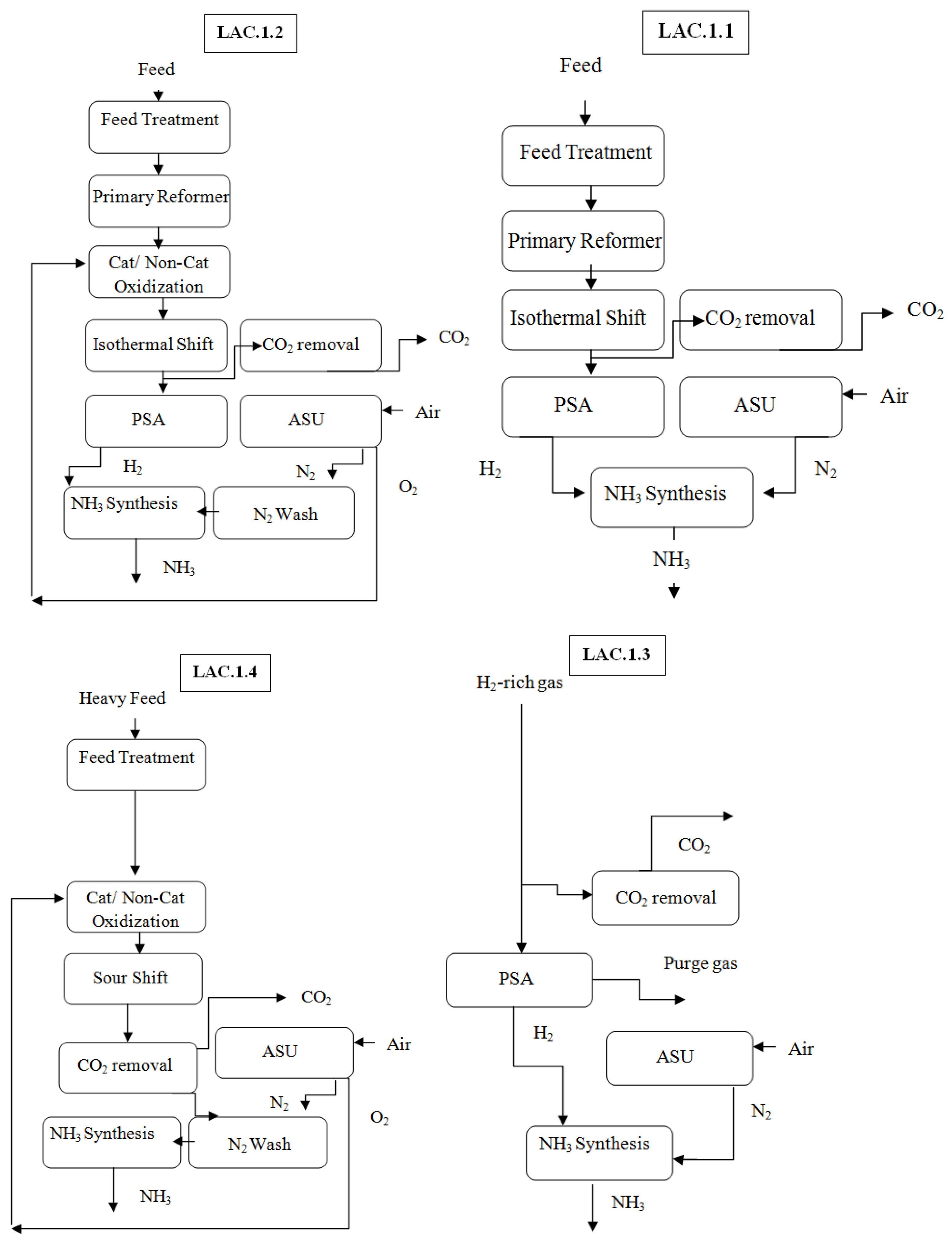
3.2.2. Linde–Ammonia Concept
3.2.3. Linde Ammonia Concept Subcategories
4. Ammonia Health and Safety Considerations
4.1. Exposure Limits
4.2. Behavior on Release to the Environment
4.3. Materials Selection
4.4. Flammability Risk
5. Discussion
6. Conclusions
Author Contributions
Funding
Institutional Review Board Statement
Informed Consent Statement
Conflicts of Interest
Nomenclature
| ASU | Air Separation Unit |
| ATR | Autothermal Reformer |
| AWE | Alkaline–water electrolysis |
| BWF | Boiler Water Feed |
| FTR | Fired Tubular Reformer |
| HB | Haber–Bosch |
| HP | High-Pressure |
| HTS | High-Temperature-Shift |
| ICI | Imperial Chemical Industries |
| IP | Intermediate pressure |
| IS | Isothermal Shift |
| i-WGS | Isothermal water gas shift |
| KAAP | KBR Advanced Ammonia Processing |
| KBR | Kellogg Brown and Root |
| KRES | KBR Reforming Exchanger System |
| LAC | Linde–Ammonia Concept |
| LTS | Low-Temperature Shift |
| MDEA | Methyldiethanolamine |
| MEA | Monoethanolamine |
| MTPD | Metric Tons Per Day |
| MTS | Medium-Temperature Shift |
| MWK | M.W. Kellogg |
| POX | Partial oxidation |
| PRF | Primary reformer furnace |
| PSA | Pressure swing adsorption |
| SMR | Steam–Methane-Reforming |
| SNG | Syngas |
| SRKC | Steam Rankine Cycle |
| SYN | Synthesis |
| TKIS | ThyssenKrupp Industrial Solutions |
| WGS | Water Gas Shift |
| SMR | Steam–Methane-Reforming |
| HP | High-Pressure |
| BWF | Boiler Water Feed |
| HB | Haber–Bosch |
| HTS | High-Temperature Shift |
| LTS | Low-Temperature Shift |
| WGS | Water–Gas Shift |
| MDEA | Methyldiethanolamine |
| MTPD | Metric Tons Per Day |
| MEA | Monoethanolamine |
| SRKC | Steam Rankine Cycle |
| POX | Partial oxidation |
| SYN | Synthesis |
| ATR | Autothermal Reformer |
| MTS | Medium-Temperature Shift |
| PSA | Pressure swing adsorption |
| TKIS | ThyssenKrupp Industrial Solutions |
| AWE | Alkaline–water electrolysis |
| ASU | Air Separation Unit |
| SNG | Syngas |
| KBR | Kellogg Brown and Root |
| MWK | M.W. Kellogg |
| ICI | Imperial Chemical Industries |
| KRES | KBR Reforming Exchanger System |
| KAAP | KBR Advanced Ammonia Processing |
| MTPD | Metric Tons Per Day |
| LAC | Linde–Ammonia Concept |
| FTR | Fired Tubular Reformer |
| i-WGS | Isothermal water gas shift |
| IP | Intermediate pressure |
| IS | Isothermal Shift |
| PRF | Primary reformer furnace |
References
- Cheremisinoff, N.P.; Rosenfeld, P. Industry and Products. In Handbook of Pollution Prevention and Cleaner Production; Elsevier: Amsterdam, The Netherlands, 2011; pp. 1–24. [Google Scholar] [CrossRef]
- Modak, J.M. Haber process for ammonia synthesis. Resonance 2002, 7, 69–77. [Google Scholar] [CrossRef]
- van Rooij, A. Engineering contractors in the chemical industry. the development of ammonia processes, 1910–1940. HistTechnol 2005, 21, 345–366. [Google Scholar] [CrossRef]
- Tso, W.W.; Demirhan, C.D.; Powell, J.B.; Pistikopoulos, E.N. Toward Optimal Synthesis of Renewable Ammonia and Methanol Processes (RAMP). Comput. Aided Chem. Eng. 2018, 44, 1705–1710. [Google Scholar] [CrossRef]
- Pearson, A. Refrigeration with ammonia. Int. J. Refrig. 2008, 31, 545–551. [Google Scholar] [CrossRef]
- Kusmanov, S.A.; Smirnov, A.A.; Kusmanova, Y.V.; Belkin, P.N. Anode plasma electrolytic nitrohardening of medium carbon steel. Surf. Coat. Technol. 2015, 269, 308–313. [Google Scholar] [CrossRef]
- Kristiana, I.; Lethorn, A.; Joll, C.; Heitz, A. To add or not to add: The use of quenching agents for the analysis of disinfection by-products in water samples. Water Res. 2014, 59, 90–98. [Google Scholar] [CrossRef]
- Brightling, J. Ammonia and the Fertiliser Industry: The Development of Ammonia at Billingham. Johns. Matthey Technol. Rev. 2018, 62, 32–47. [Google Scholar] [CrossRef]
- Rafiqul, I.; Weber, C.; Lehmann, B.; Voss, A. Energy efficiency improvements in ammonia production—Perspectives and uncertainties. Energy 2005, 30, 2487–2504. [Google Scholar] [CrossRef]
- Aalrebei, O.F.; Al Assaf, A.H.; Amhamed, A.; Swaminathan, N.; Hewlett, S. Ammonia-hydrogen-air gas turbine cycle and control analyses. Int. J. Hydrogen Energy 2022, 47, 8603–8620. [Google Scholar] [CrossRef]
- Ratnasamy, C.; Wagner, J.P. Water Gas Shift Catalysis. Catal. Rev. 2009, 51, 325–440. [Google Scholar] [CrossRef]
- Gao, J.; Wang, Y.; Ping, Y.; Hu, D.; Xu, G.; Gu, F.; Su, F. A thermodynamic analysis of methanation reactions of carbon oxides for the production of synthetic natural gas. RSC Adv. 2012, 2, 2358. [Google Scholar] [CrossRef]
- Sanchez, A.; Martín, M. Scale up and scale down issues of renewable ammonia plants: Towards modular design. Sustain. Prod. Consum. 2018, 16, 176–192. [Google Scholar] [CrossRef]
- Kandemir, T.; Schuster, M.E.; Senyshyn, A.; Behrens, M.; Schlögl, R. The Haber-Bosch Process Revisited: On the Real Structure and Stability of “Ammonia Iron” under Working Conditions. Angew. Chem. Int. Ed. 2013, 52, 12723–12726. [Google Scholar] [CrossRef] [PubMed]
- Haber, F.; Le Rossignol, R. Production of Ammonia. U.S. Patent 1202995A, 13 August 1909. Available online: https://patents.google.com/patent/US1202995A/en?oq=(U.S+patent+1202995) (accessed on 16 January 2021).
- Wright, L.; Pickford, A. Ammonia Synthesis System. U.S. Patent 3721532A, 8 February 1971. Available online: https://patents.google.com/patent/US3721532A/en (accessed on 27 January 2021).
- Da Rosa, A.V. Process for Production of Ammonia. U.S. Patent 4107277A, 15 August 1978. Available online: https://patents.google.com/patent/US4107277A/en (accessed on 16 January 2022).
- Becker, C.L. Low Energy Ammonia Synthesis Process. U.S. Patent 4148866, 4 October 1976. Available online: https://patents.google.com/patent/US4153673A/en (accessed on 16 January 2022).
- Shires, P.J.; Cassata, J.R.; Mandelik, B.G.; Dijk, C.P. Preparation of Ammonia Synthesis Gas. U.S. Patent 4479925, 30 October 1984. [Google Scholar]
- Pinto, A.; Johnson, J.B.H. Ammonia Synthesis Process. U.S. Patent 4695442A, 20 February 1985. Available online: https://patents.google.com/patent/US4695442A/en (accessed on 1 February 2022).
- Francesco, B. Ammonia Process A60TM 2019. Available online: https://www.casale.ch/downloads/ammonia (accessed on 30 October 2020).
- Molino, A.; Nanna, F.; Ding, Y.; Bikson, B.; Braccio, G. Biomethane production by anaerobic digestion of organic waste. Fuel 2013, 103, 1003–1009. [Google Scholar] [CrossRef]
- Zheng, Y.; Zhao, J.; Xu, F.; Li, Y. Pretreatment of lignocellulosic biomass for enhanced biogas production. Prog. Energy Combust. Sci. 2014, 42, 35–53. [Google Scholar] [CrossRef]
- Ding, L.; Cheng, J.; Xia, A.; Jacob, A.; Voelklein, M.; Murphy, J.D. Co-generation of biohydrogen and biomethane through two-stage batch co-fermentation of macro-and micro-algal biomass. BioresourTechnol 2016, 218, 224–231. [Google Scholar] [CrossRef]
- Andersson, J.; Lundgren, J. Techno-economic analysis of ammonia production via integrated biomass gasification. Appl Energy 2014, 130, 484–940. [Google Scholar] [CrossRef] [Green Version]
- Tock, L.; Mar´echal, F.; Perrenoud, M. Thermo-environomic evaluation of the ammonia production. Can. J. ChemEng. 2015, 93, 356–362. [Google Scholar] [CrossRef]
- Gilbert, P.; Alexander, S.; Thornley, P.; Brammer, J. Assessing economically viable carbon reductions for the production of ammonia from biomass gasification. J. Clean. Prod. 2014, 64, 581–589. [Google Scholar] [CrossRef]
- Hoffman, B.M.; Lukoyanov, D.; Dean, D.R.; Seefeldt, L.C. Nitrogenase: A draft mechanism. AccChem. Res. 2013, 46, 87–95. [Google Scholar] [CrossRef] [Green Version]
- Li, Y.; Li, Y.; Wang, B.; Luo, Y.; Yang, D.; Tong, P.; Zhao, J.; Luo, L.; Zhou, Y.; Chen, S.; et al. Ammonia formation by a thiolate-bridged diiron amide complex as a nitrogenase mimic. Nat. Chem. 2013, 5, 320–326. [Google Scholar] [CrossRef] [PubMed]
- Anderson, J.S.; Rittle, J.; Peters, J.C. Catalytic conversion of nitrogen to ammonia by an iron model complex. Nature 2013, 501, 84–87. [Google Scholar] [CrossRef] [PubMed] [Green Version]
- Larsen, J.S.; Lippmann, D. The Uhde Dual Pressure Process-Reliability Issues and Scale-Up Considerations The Uhde Dual Pressure Process-Reliability Issues and Scale-Up Considerations. In Proceedings of the 47th Annual Safety in Ammonia Plants and Related Facilities Symposium, San Diego, CA, USA, 16–September 2002. [Google Scholar]
- Thyssenkrupp Industrial Solutions. Small-Scale Green Ammonia Plants Open up New Storage Possibilities for Wind and Solar Power. n.d. Available online: https://insights.thyssenkrupp-industrial-solutions.com/story/small-scale-green-ammonia-plants-open-up-new-storage-possibilities-for-wind-and-solar-power/ (accessed on 30 October 2020).
- David, M.; Ocampo-Martínez, C.; Sanchez-Pena, R. Advances in alkaline water electrolyzers: A review. J. Energy Storage 2019, 23, 392–403. [Google Scholar] [CrossRef] [Green Version]
- Araújo, A.; Skogestad, S. Control structure design for the ammonia synthesis process. Comput. Chem. Eng. 2008, 32, 2920–2932. [Google Scholar] [CrossRef] [Green Version]
- Gosnell, J.; Malhotra, A. New Ammonia Process. Ammon. Plant SafRelatFacil 2000, 40, 116–125. [Google Scholar]
- Eskicioglu, C.; Galvagno, G.; Cimon, C. Approaches and processes for ammonia removal from side-streams of municipal effluent treatment plants. Bioresour. Technol. 2018, 268, 797–810. [Google Scholar] [CrossRef]
- Linde Engineering, LAC™ (the Linde Ammonia Concept). Available online: https://www.linde-engineering.com/en/process-plants/hydrogen_and_synthesis_gas_plants/gas_products/ammonia/index.html (accessed on 12 January 2021).
- Lin, B.; Heng, L.; Fang, B.; Yin, H.; Ni, J.; Wang, X.; Lin, J.; Jiang, L. Ammonia Synthesis Activity of Alumina-Supported Ruthenium Catalyst Enhanced by Alumina Phase Transformation. ACS Catal. 2019, 9, 1635–1644. [Google Scholar] [CrossRef]
- Pattabathula, V.; Richardson, J. Introduction to ammonia production. Chem. Eng. Prog. 2016, 112, 69–75. [Google Scholar]
- Akpa, J.G.; Raphael, N.R. Optimization of an Ammonia Synthesis Converter. World J. Eng. Technol. 2014, 2, 305. [Google Scholar] [CrossRef] [Green Version]
- National Academies. Ammonia Final AEGL Document. 2008. Available online: http://www.nap.edu/catalog/12018.html (accessed on 14 April 2022).
- Health and Safety Executive. EH40/2005 Workplace Exposure Limits EH40, 2nd ed.; HSE Books: London, UK, 2011.
- Adam, M.R.; Othman, M.H.D.; Abu Samah, R.; Puteh, M.H.; Ismail, A.; Mustafa, A.; Rahman, M.A.; Jaafar, J. Current trends and future prospects of ammonia removal in wastewater: A comprehensive review on adsorptive membrane development. Sep. Purif. Technol. 2019, 213, 114–132. [Google Scholar] [CrossRef]
- The Royal Society. Ammonia: Zero-Carbon Fertiliser, Fuel and Energy Store. Policy Briefing. 2020. Available online: https://royalsociety.org/topics-policy/projects/low-carbon-energy-programme/green-ammonia/ (accessed on 12 July 2021).
- Health & Safety Executive. COMAH—Guidance—Technical Aspects—Measures Documents—Corrosion/Selection of Materials. Available online: http://www.hse.gov.uk/comah/sragtech/techmeasmaterial.htm (accessed on 14 November 2021).
- Cole-Parmer Instrument Company. Chemical Compatibility Database from Cole-Parmer United Kingdom. 2021. Available online: https://www.coleparmer.co.uk/Chemical-Resistance (accessed on 5 January 2022).
- Verkamp, F.J.; Hardin, M.C.; Williams, J.R. Ammonia combustion properties and performance in gas-turbine burners. Symp. Combust. 1967, 11, 985–992. [Google Scholar] [CrossRef]
- Lees, F. Electrostatic hazards: Their evaluation and control: By Heinz Haase; published by Verlag Chemie, New York, 1976; x + 125 pp.; price DM 24.00. Chem. Eng. J. 1977, 14, 229. [Google Scholar] [CrossRef]
- Kobayashi, H.; Hayakawa, A.; Somarathne, K.K.A.; Okafor, E.C. Science and technology of ammonia combustion. Proc. Combust. Inst. 2019, 37, 109–133. [Google Scholar] [CrossRef]
- McAllister, S.; Chen, J.-Y.; Fernandez-Pello, A.C. Fundamentals of Combustion Processes. In Fundamentals of Combustion Processes; Springer: New York, NY, USA, 2011; pp. 15–47. [Google Scholar] [CrossRef]
- Verleysen, K.; Coppitters, D.; Parente, A.; De Paepe, W.; Contino, F. How can power-to-ammonia be robust? Optimization of an ammonia synthesis plant powered by a wind turbine considering operational uncertainties. Fuel 2016, 266, 117049. [Google Scholar] [CrossRef]
- Zhang, S.; Zhao, Y.; Shi, R.; Waterhouse, G.I.; Zhang, T. Photocatalytic ammonia synthesis: Recent progress and future. EnergyChem 2019, 1, 100013. [Google Scholar] [CrossRef]
- Mohamed, A.M.; Bicer, Y. Development and assessment of concentrated solar energy driven ammonia synthesis from liquefied natural gas. Int. J. Hydrogen Energy 2020, 46, 10093–10103. [Google Scholar] [CrossRef]
- Siddiqui, O.; Dincer, I. Development and evaluation of a solar-based integrated ammonia synthesis and fuel cell system. J. Clean. Prod. 2020, 256, 120393. [Google Scholar] [CrossRef]
- Fasihi, M.; Weiss, R.; Savolainen, J.; Breyer, C. Global potential of green ammonia based on hybrid PV-wind power plants. Appl. Energy 2021, 294, 116170. [Google Scholar] [CrossRef]
- Ghavam, S.; Vahdati, M.; Wilson, I.A.; Styring, P. Sustainable ammonia production processes. Front. Energy Res. 2021, 9, 34. [Google Scholar] [CrossRef]
- Palys, M.J.; Wang, H.; Zhang, Q.; Daoutidis, P. Renewable ammonia for sustainable energy and agriculture: Vision and systems engineering opportunities. Curr. Opin. Chem. Eng. 2021, 31, 100667. [Google Scholar] [CrossRef]
- Armijo, J.; Philibert, C. Flexible production of green hydrogen and ammonia from variable solar and wind energy: Case study of Chile and Argentina. Int. J. Hydrogen Energy 2019, 45, 1541–1558. [Google Scholar] [CrossRef]
- Liu, X.; Elgowainy, A.; Wang, M. Life cycle energy use and greenhouse gas emissions of ammonia production from renewable resources and industrial by-products. Green Chem. 2020, 22, 5751–5761. [Google Scholar] [CrossRef]
- Cesaro, Z.; Ives, M.; Nayak-Luke, R.; Mason, M.; Bañares-Alcántara, R. Ammonia to power: Forecasting the levelized cost of electricity from green ammonia in large-scale power plants. Appl. Energy 2021, 282, 116009. [Google Scholar] [CrossRef]
- Siddiqui, O.; Dincer, I. A new solar energy system for ammonia production and utilization in fuel cells. Energy Convers. Manag. 2020, 208, 112590. [Google Scholar] [CrossRef]
- Cloete, S.; Khan, M.N.; Nazir, S.M.; Amini, S. Cost-effective clean ammonia production using membrane-assisted autothermal reforming. Chem. Eng. J. 2020, 404, 126550. [Google Scholar] [CrossRef]
- Osman, O.; Sgouridis, S.; Sleptchenko, A. Scaling the production of renewable ammonia: A techno-economic optimization applied in regions with high insolation. J. Clean. Prod. 2020, 271, 121627. [Google Scholar] [CrossRef]
- Yan, Z.; Ji, M.; Xia, J.; Zhu, H. Recent advanced materials for electrochemical and photoelectro-chemical synthesis of ammonia from dinitrogen: One step closer to a sustainable energy future. Adv. Energy Mater. 2020, 10, 1902020. [Google Scholar] [CrossRef]
- Hollevoet, L.; De Ras, M.; Roeffaers, M.; Hofkens, J.; Martens, J.A. Energy-Efficient Ammonia Production from Air and Water Using Electrocatalysts with Limited Faradaic Efficiency. ACS Energy Lett. 2020, 5, 1124–1127. [Google Scholar] [CrossRef] [Green Version]
- Salmon, N.; Bañares-Alcántara, R. Green ammonia as a spatial energy vector: A review. Sustain. Energy Fuels 2021, 5, 2814–2839. [Google Scholar] [CrossRef]
- Flórez-Orrego, D.; Sharma, S.; de Oliveira Junior, S.; Marechal, F. Combined exergy analysis, energy integration and optimization of syngas and ammonia production plants: A cogeneration and syngas purification perspective. J. Clean. Prod. 2020, 244, 118647. [Google Scholar] [CrossRef]
- Hasan, A.; Dincer, I. An ocean thermal energy conversion based system for district cooling, ammonia and power production. Int. J. Hydrogen Energy 2020, 45, 15878–15887. [Google Scholar] [CrossRef]
- Peng, X.; Liu, H.-X.; Zhang, Y.; Huang, Z.-Q.; Yang, L.; Jiang, Y.; Wang, X.; Zheng, L.; Chang, C.; Au, C.-T.; et al. Highly efficient ammonia synthesis at low temperature over a Ru–Co catalyst with dual atomically dispersed active centers. Chem. Sci. 2021, 12, 7125–7137. [Google Scholar] [CrossRef] [PubMed]
- Ishaq, H.; Dincer, I. Dynamic analysis of a new solar-wind energy-based cascaded system for hydrogen to ammonia. Int. J. Hydrogen Energy 2020, 45, 18895–18911. [Google Scholar] [CrossRef]
- Demirhan, C.D.; Tso, W.W.; Powell, J.B.; Pistikopoulos, E.N. Sustainable ammonia production through process synthesis and global optimization. AIChE J. 2018, 65, e16498. [Google Scholar] [CrossRef]
- Philibert, C. Producing Ammonia and Fertilizers: New Opportunities from Renewables; IEA Rep: Paris, France, 2017; pp. 1–6. [Google Scholar]
- Nørskov, J.; Chen, J.; Miranda, R.; Fitzsimmons, T.; Stack, R. Sustainable Ammonia Synthesis–Exploring the Scientific Challenges Associated with Discovering Alternative, Sustainable Processes for Ammonia Production; US DOE Office of Science: Washington, DC, USA, 2016.
- Jiang, J.; Feng, X. Energy optimization of ammonia synthesis processes based on oxygen purity under different purification technologies. Energy 2019, 185, 819–828. [Google Scholar] [CrossRef]
- Sanchez, A.; Martín, M. Optimal renewable production of ammonia from water and air. J. Clean. Prod. 2018, 178, 325–342. [Google Scholar] [CrossRef]
- Beerbühl, S.S.; Fröhling, M.; Schultmann, F. Combined scheduling and capacity planning of electricity-based ammonia production to integrate renewable energies. Eur. J. Oper. Res. 2015, 241, 851–862. [Google Scholar] [CrossRef]
- Nosherwani, S.A.; Neto, R.C. Techno-economic assessment of commercial ammonia synthesis methods in coastal areas of Germany. J. Energy Storage 2021, 34, 102201. [Google Scholar] [CrossRef]
- Yoshida, M.; Ogawa, T.; Imamura, Y.; Ishihara, K.N. Economies of scale in ammonia synthesis loops embedded with iron- and ruthenium-based catalysts. Int. J. Hydrogen Energy 2021, 46, 28840–28854. [Google Scholar] [CrossRef]
- Guerra, C.F.; Reyes-Bozo, L.; Vyhmeister, E.; Caparrós, M.J.; Salazar, J.L.; Clemente-Jul, C. Technical-economic analysis for a green ammonia production plant in Chile and its subsequent transport to Japan. Renew. Energy 2020, 157, 404–414. [Google Scholar] [CrossRef]
- Ziaei, M.; Panahi, M.; Fanaei, M.A.; Rafiee, A.; Khalilpour, K.R. Maximizing the prof-itability of integrated Fischer-Tropsch GTL process with ammonia and urea synthesis using response surface methodology. J. CO2 Util. 2020, 35, 14–27. [Google Scholar] [CrossRef]
- Graça, V.C.; Loureiro, F.J.; Holz, L.I.; Mikhalev, S.M.; Araújo, A.J.; Fagg, D.P. Electrochemical ammonia synthesis: Mechanism, recent developments, and challenges in catalyst design. Heterog. Catal. 2022, 497–514. [Google Scholar]
- del Pozo, C.A.; Cloete, S. Techno-economic assessment of blue and green ammonia as energy carriers in a low-carbon future. Energy Convers. Manag. 2022, 255, 115312. [Google Scholar] [CrossRef]
- Gomez, J.R.; Baca, J.; Garzon, F. Techno-economic analysis and life cycle assessment for electrochemical ammonia production using proton conducting membrane. Int. J. Hydrogen Energy 2019, 45, 721–737. [Google Scholar] [CrossRef]
- Hochman, G.; Goldman, A.S.; Felder, F.A.; Mayer, J.M.; Miller, A.J.M.; Holland, P.L.; Goldman, L.A.; Manocha, P.; Song, Z.; Aleti, S. Potential Economic Feasibility of Direct Electrochemical Nitrogen Reduction as a Route to Ammonia. ACS Sustain. Chem. Eng. 2020, 8, 8938–8948. [Google Scholar] [CrossRef]
- Smith, C.; Torrente-Murciano, L. The potential of green ammonia for agricultural and economic development in Sierra Leone. One Earth 2021, 4, 104–113. [Google Scholar] [CrossRef]
- Morlanés, N.; Katikaneni, S.P.; Paglieri, S.N.; Harale, A.; Solami, B.; Sarathy, S.M.; Gascon, J. A technological roadmap to the ammonia energy economy: Current state and missing technologies. Chem. Eng. J. 2020, 408, 127310. [Google Scholar] [CrossRef]
- Zang, G.; Sun, P.; Elgowainy, A.; Wang, M. Technoeconomic and Life Cycle Analysis of Synthetic Methanol Production from Hydrogen and Industrial Byproduct CO2. Environ. Sci. Technol. 2021, 55, 5248–5257. [Google Scholar] [CrossRef]
- Fernandez, C.A.; Hatzell, M.C. Editors’ Choice—Economic Considerations for Low-Temperature Electrochemical Ammonia Production: Achieving Haber-Bosch Parity. J. Electrochem. Soc. 2020, 167, 143504. [Google Scholar] [CrossRef]
- MacFarlane, D.R.; Cherepanov, P.V.; Choi, J.; Suryanto, B.H.; Hodgetts, R.Y.; Bakker, J.M.; Vallana, F.M.F.; Simonov, A.N. A Roadmap to the Ammonia Economy. Joule 2020, 4, 1186–1205. [Google Scholar] [CrossRef]
- Lin, B.; Theodore, W.; Mahdi, M. Performance of a small-scale Haber process: A techno-economic analysis. ACS Sustain. Chem. Eng. 2020, 8, 15517–15531. [Google Scholar] [CrossRef]
- Bose, A.; Nikifar, L.; Michal, G.; Karthish, M.; Dharik, M. Spatial variation in cost of electricity-driven continuous ammonia production in the United States. ACS Sustain. Chem. Eng. 2022, 10, 7862–7872. [Google Scholar] [CrossRef]
- Nayak-Luke, R.M.; Bañares-Alcántara, R. Techno-economic viability of islanded green ammonia as a carbon-free energy vector and as a substitute for conventional production. Energy Environ. Sci. 2020, 13, 2957–2966. [Google Scholar] [CrossRef]
- Nayak-Luke, R.M.; Forbes, C.; Cesaro, Z.; Bañares-Alcántara, R.; Rouwenhorst KH, R. Techno-Economic Aspects of Production, Storage and Distribution of Ammonia. In Techno-Economic Challenges of Green Ammonia as Energy Vector; Bañares-Alcántara, R., Valera-Medina, A., Eds.; Elsevier: Amsterdam, The Netherlands, 2020; pp. 191–208. [Google Scholar]
- Morgan, E.R.; Manwell, J.F.; McGowan, J.G. Sustainable Ammonia Production from U.S. Offshore Wind Farms: A Techno-Economic Review. ACS Sustain. Chem. Eng. 2017, 5, 9554–9567. [Google Scholar] [CrossRef]
- Demirel, Y.; Matzen, M.; Alhajji, M. Technoeconomics and Sustainability of Renewable Methanol and Ammonia Productions Using Wind Power-based Hydrogen. J. Adv. Chem. Eng. 2015, 5. [Google Scholar] [CrossRef] [Green Version]
- Akbari, M.; Oyedun, A.O.; Kumar, A. Ammonia production from black liquor gasification and co-gasification with pulp and waste sludges: A techno-economic assessment. Energy 2018, 151, 133–143. [Google Scholar] [CrossRef]
- Yáñez, M.; Relvas, F.M.; Ortiz, A.; Gorri, D.; Mendes, A.; Ortiz, I. PSA purification of waste hydrogen from ammonia plants to fuel cell grade. Sep. Purif. Technol. 2019, 240, 116334. [Google Scholar] [CrossRef]
- Valera-Medina, A.; Amer-Hatem, F.; Azad, A.K.; Dedoussi, I.C.; de Joannon, M.; Fernandes, R.X.; Glarborg, P.; Hashemi, H.; He, X.; Mashruk, S.; et al. Review on Ammonia as a Potential Fuel: From Synthesis to Economics. Energy Fuels 2021, 35, 6964–7029. [Google Scholar] [CrossRef]
- Ghavam, S.; Garcia-Garcia, G.; Styring, P. A novel approach to ammonia synthesis from hydrogen sulfide. Int. J. Hydrogen Energy 2020, 46, 4072–4086. [Google Scholar] [CrossRef]
- Sadeek, S.; Chan, T.L.; Ramdath, R.; Rajkumar, A.; Guo, M.; Ward, K. The influence of raw material availability and utility power consumption on the sustainability of the ammonia process. Chem. Eng. Res. Des. 2020, 158, 177–192. [Google Scholar] [CrossRef]
- Long, J.; Chen, S.; Zhang, Y.; Guo, C.; Fu, X.; Deng, D.; Xiao, J. Direct Electrochemical Ammonia Synthesis from Nitric Oxide. Angew. Chem. Int. Ed. 2020, 59, 9711–9718. [Google Scholar] [CrossRef] [PubMed]
- Bicer, Y.; Khalid, F. Life cycle environmental impact comparison of solid oxide fuel cells fueled by natural gas, hydrogen, ammonia and methanol for combined heat and power generation. Int. J. Hydrogen Energy 2020, 45, 3670–3685. [Google Scholar] [CrossRef]
- Al-Aboosi, F.Y.; Mahmoud, M.E.-H.; Margaux, M.; Rasmus, B.N. Renewable ammonia as an alter-native fuel for the shipping industry. Curr. Opin. Chem. Eng. 2021, 31, 100670. [Google Scholar] [CrossRef]
- Lazouski, N.; Chung, M.; Williams, K.; Gala, M.L.; Manthiram, K. Non-aqueous gas diffusion electrodes for rapid ammonia synthesis from nitrogen and water-splitting-derived hydrogen. Nat. Catal. 2020, 3, 463–469. [Google Scholar] [CrossRef]
- Sajid, M.U.; Bicer, Y. Thermodynamic assessment of chemical looping combustion and solar thermal methane cracking-based integrated system for green ammonia production. Therm. Sci. Eng. Prog. 2020, 19, 100588. [Google Scholar] [CrossRef]
- Hansson, J.; Brynolf, S.; Fridell, E.; Lehtveer, M. The Potential Role of Ammonia as Marine Fuel—Based on Energy Systems Modeling and Multi-Criteria Decision Analysis. Sustainability 2020, 12, 3265. [Google Scholar] [CrossRef] [Green Version]
- Sharma, R.K.; Patel, H.; Mushtaq, U.; Kyriakou, V.; Zafeiropoulos, G.; Peeters, F.; Welzel, S.; van de Sanden, M.C.M.; Tsampas, M.N. Plasma Activated Electrochemical Ammonia Synthesis from Nitrogen and Water. ACS Energy Lett. 2020, 6, 313–319. [Google Scholar] [CrossRef]
- Alrebei, O.F.; Al-Doboon, A.; Bowen, P.; Medina, A.V. CO2-Argon-Steam Oxy-Fuel Production for (CARSOXY) Gas Turbines. Energies 2019, 12, 3580. [Google Scholar] [CrossRef] [Green Version]
- Fawwaz Alrebei, O.I.; Amhamed, A.; Mashruk, S.; Bowen, P.; Valera Medina, A. Planar la-ser-induced fluorescence and chemiluminescence analyses of CO2-argon-steam oxyfuel (CARSOXY) combustion. Energies 2021, 15, 263. [Google Scholar] [CrossRef]
- Alrebei, O.F.; Bowen, P.; Medina, A.V. Parametric Study of Various Thermodynamic Cycles for the Use of Unconventional Blends. Energies 2020, 13, 4656. [Google Scholar] [CrossRef]
- Alrebei, O.F.; Amhamed, A.I.; El-Naas, M.H.; Hayajnh, M.; Orabi, Y.A.; Fawaz, W.; Al-Tawaha, A.S.; Medina, A.V. State of the Art in Separation Processes for Alternative Working Fluids in Clean and Efficient Power Generation. Separations 2022, 9, 14. [Google Scholar] [CrossRef]
- Chehade, G.; Dincer, I. Development and analysis of a polygenerational smart energy hub for sustainable communities. Energy Convers. Manag. 2020, 226, 113475. [Google Scholar] [CrossRef]
- Pfromm, P.H. Towards sustainable agriculture: Fossil-free ammonia. J. Renew. Sustain. Energy 2017, 9, 034702. [Google Scholar] [CrossRef] [Green Version]
- Frattini, D.; Cinti, G.; Bidini, G.; Desideri, U.; Cioffi, R.; Jannelli, E. A system approach in energy evaluation of different renewable energies sources integration in ammonia production plants. Renew. Energy 2016, 99, 472–482. [Google Scholar] [CrossRef]
- McEnaney, J.M.; Singh, A.R.; Schwalbe, J.A.; Kibsgaard, J.; Lin, J.C.; Cargnello, M.; Nørskov, J.K. Ammonia synthesis from N2 and H2O using a lithium cycling electrification strategy at atmospheric pressure. Energy Environ. Sci. 2017, 10, 1621–1630. [Google Scholar] [CrossRef] [Green Version]
- Cinti, G.; Frattini, D.; Jannelli, E.; Desideri, U.; Bidini, G. Coupling Solid Oxide Electrolyser (SOE) and ammonia production plant. Appl. Energy 2017, 192, 466–476. [Google Scholar] [CrossRef] [Green Version]
- Ghannadzadeh, A.; Sadeqzadeh, M. Diagnosis of an alternative ammonia process technology to reduce exergy losses. Energy Convers. Manag. 2016, 109, 63–70. [Google Scholar] [CrossRef]
- Bicer, Y.; Dincer, I. Life cycle assessment of nuclear-based hydrogen and ammonia production options: A comparative evaluation. Int. J. Hydrogen Energy 2017, 42, 21559–21570. [Google Scholar] [CrossRef]
- Wang, M.; Khan, M.A.; Mohsin, I.; Wicks, J.; Ip, A.H.; Sumon, K.Z.; Dinh, C.-T.; Sargent, E.H.; Gates, I.D.; Kibria, G. Can sustainable ammonia synthesis pathways compete with fossil-fuel based Haber–Bosch processes? Energy Environ. Sci. 2021, 14, 2535–2548. [Google Scholar] [CrossRef]
- Rouwenhorst, K.H.; Lefferts, L. Feasibility study of plasma-catalytic ammonia synthesis for energy storage applications. Catalysts 2020, 10, 999. [Google Scholar] [CrossRef]
- Barboun, P.M.; Hicks, J.C. Unconventional catalytic approaches to ammonia synthesis. Annu. Rev. Chem. Biomol. Eng. 2020, 11, 503–521. [Google Scholar] [CrossRef] [PubMed] [Green Version]
- An, Q.; Mcdonald, M.; Fortunelli, A.; Goddard, W.A. Si-Doped Fe Catalyst for Ammonia Synthesis at Dramatically Decreased Pressures and Temperatures. J. Am. Chem. Soc. 2020, 142, 8223–8232. [Google Scholar] [CrossRef] [PubMed] [Green Version]
- Yang, B.; Ding, W.; Zhang, H.; Zhang, S. Recent progress in electrochemical synthesis of ammonia from nitrogen: Strategies to improve the catalytic activity and selectivity. Energy Environ. Sci. 2021, 14, 672–687. [Google Scholar] [CrossRef]
- Hao, D.; Chen, Z.-G.; Figiela, M.; Stepniak, I.; Wei, W.; Ni, B.-J. Emerging alternative for artificial ammonia synthesis through catalytic nitrate reduction. J. Mater. Sci. Technol. 2021, 77, 163–168. [Google Scholar] [CrossRef]
- Patil, B.S.; Cherkasov, N.; Srinath, N.V.; Lang, J.; Ibhadon, A.O.; Wang, Q.; Hessel, V. The role of heterogeneous catalysts in the plasma-catalytic ammonia synthesis. Catal. Today 2021, 362, 2–10. [Google Scholar] [CrossRef]
- Ooya, K.; Li, J.; Fukui, K.; Iimura, S.; Nakao, T.; Ogasawara, K.; Sasase, M.; Abe, H.; Niwa, Y.; Kitano, M.; et al. Ruthenium Catalysts Promoted by Lanthanide Oxyhydrides with High Hydride-Ion Mobility for Low-Temperature Ammonia Synthesis. Adv. Energy Mater. 2021, 11, 2003723. [Google Scholar] [CrossRef]
- Hollevoet, L.; Jardali, F.; Gorbanev, Y.; Creel, J.; Bogaerts, A.; Martens, J.A. Towards Green Ammonia Synthesis through Plasma-Driven Nitrogen Oxidation and Catalytic Reduction. Angew. Chem. 2020, 132, 24033–24037. [Google Scholar] [CrossRef]
- Humphreys, J.; Lan, R.; Chen, S.; Tao, S. Improved stability and activity of Fe-based catalysts through strong metal support interactions due to extrinsic oxygen vacancies in Ce0.8Sm0.2O2−δ for the efficient synthesis of ammonia. J. Mater. Chem. A 2020, 8, 16676–16689. [Google Scholar] [CrossRef]
- Nanba, T.; Nagata, Y.; Kobayashi, K.; Javaid, R.; Atsumi, R.; Nishi, M.; Mochizuki, T.; Manaka, Y.; Kojima, H.; Tsujimura, T.; et al. Explorative Study of a Ru/CeO2 Catalyst for NH3 Synthesis from Renewable Hydrogen and Demonstration of NH3 Synthesis under a Range of Reaction Conditions. J. Jpn. Pet. Inst. 2021, 64, 1–9. [Google Scholar] [CrossRef]
- Wang, J.; Feng, T.; Chen, J.; Ramalingam, V.; Li, Z.; Kabtamu, D.M.; Fang, X. Electrocatalytic nitrate/nitrite reduction to ammonia synthesis using metal nanocatalysts and bio-inspired metalloen-zymes. Nano Energy 2021, 86, 106088. [Google Scholar] [CrossRef]
- Patil, B.S.; Van Kaathoven, A.S.; Peeters, F.J.; Cherkasov, N.; Lang, J.; Wang, Q.; Hessel, V. Deciphering the synergy between plasma and catalyst support for ammonia synthesis in a packed dielectric barrier discharge reactor. J. Phys. D Appl. Phys. 2020, 53, 144003. [Google Scholar] [CrossRef]
- Utomo, W.P.; Leung, M.K.H.; Yin, Z.; Wu, H.; Ng, Y.H. Advancement of Bismuth-Based Materials for Electrocatalytic and Photo(electro)catalytic Ammonia Synthesis. Adv. Funct. Mater. 2021, 32, 2106713. [Google Scholar] [CrossRef]
- Carreon, M.L. Plasma catalytic ammonia synthesis: State of the art and future directions. J. Phys. D Appl. Phys. 2019, 52, 483001. [Google Scholar] [CrossRef]
- Akay, G.; Zhang, K. Process Intensification in Ammonia Synthesis Using Novel Coassembled Supported Microporous Catalysts Promoted by Nonthermal Plasma. Ind. Eng. Chem. Res. 2017, 56, 457–468. [Google Scholar] [CrossRef] [Green Version]
- Barboun, P.M.; Mehta, P.; Herrera, F.A.; Go, D.B.; Schneider, W.F.; Hicks, J.C. Distinguishing Plasma Contributions to Catalyst Performance in Plasma-Assisted Ammonia Synthesis. ACS Sustain. Chem. Eng. 2019, 7, 8621–8630. [Google Scholar] [CrossRef]
- Tang, Y.; Kobayashi, Y.; Masuda, N.; Uchida, Y.; Okamoto, H.; Kageyama, T.; Kageyama, H. Metal-Dependent Support Effects of Oxyhydride-Supported Ru, Fe, Co Catalysts for Ammonia Synthesis. Adv. Energy Mater. 2018, 8, 1801772. [Google Scholar] [CrossRef]
- Wang, H.; Li, Y.; Li, C.; Deng, K.; Wang, Z.; Xu, Y.; Wang, L. One-pot synthesis of bi-metallic PdRu tripods as an efficient catalyst for electrocatalytic nitrogen reduction to ammonia. J. Mater. Chem. A 2019, 7, 801–805. [Google Scholar] [CrossRef]
- Riotto, T.; Cao, G.; Luyben, W.L.; Baltrusaitis, J. Atmospheric Pressure DBD Plasma Ammonia Synthesis and Separation Process Design and Environmental Impact Assessment. ACS Sustain. Chem. Eng. 2021, 9, 13233–13244. [Google Scholar] [CrossRef]
- Hattori, M.; Mori, T.; Arai, T.; Inoue, Y.; Sasase, M.; Tada, T.; Kitano, M.; Yokoyama, T.; Hara, M.; Hosono, H. Enhanced Catalytic Ammonia Synthesis with Transformed BaO. ACS Catal. 2018, 8, 10977–10984. [Google Scholar] [CrossRef]
- Humphreys, J. The Development of Water and Oxygen Tolerant Catalysts for Ammonia Synthesis. Ph.D. Thesis, University of Warwick, Warwick, UK, 2019. [Google Scholar]
- Abghoui, Y.; Skúlason, E. Computational Predictions of Catalytic Activity of Zincblende (110) Surfaces of Metal Nitrides for Electrochemical Ammonia Synthesis. J. Phys. Chem. C 2017, 121, 6141–6151. [Google Scholar] [CrossRef]
- Hawtof, R.; Ghosh, S.; Guarr, E.; Xu, C.; Sankaran, R.M.; Renner, J.N. Catalyst-free, highly selective synthesis of ammonia from nitrogen and water by a plasma electrolytic system. Sci. Adv. 2019, 5, 5778. [Google Scholar] [CrossRef] [PubMed] [Green Version]
- Ogura, Y.; Tsujimaru, K.; Sato, K.; Miyahara, S.I.; Toriyama, T.; Yamamoto, T.; Nagaoka, K. Ru/La0. 5Pr0. 5O1. 75 catalyst for low-temperature ammonia synthesis. ACS Sustain. Chem. Eng. 2018, 6, 17258–17266. [Google Scholar] [CrossRef]
- Rossetti, I. Reactor Design, Modelling and Process Intensification for Ammonia Synthesis. In Sustainable Ammonia Production; Springer: Cham, Switzerland, 2020; pp. 17–48. [Google Scholar]
- Ishaq, H.; Dincer, I. Design and simulation of a new cascaded ammonia synthesis system driven by renewables. Sustain. Energy Technol. Assess. 2020, 40, 100725. [Google Scholar] [CrossRef]
- Han, Z.; Xu, Y.; Wang, H.; Tian, H.; Qiu, B.; Sun, D. Synthesis of ammonia molecularly im-printed adsorbents and ammonia adsorption separation during sludge aerobic composting. Bioresour. Technol. 2020, 300, 122670. [Google Scholar] [CrossRef]
- Kyriakou, V.; Garagounis, I.; Vourros, A.; Vasileiou, E.; Stoukides, M. An electrochemical haber-bosch process. Joule 2020, 4, 142–158. [Google Scholar] [CrossRef]
- Pereira, R.J.L.; Argyris, P.A.; Spallina, V. A comparative study on clean ammonia production using chemical looping based technology. Appl. Energy 2020, 280, 115874. [Google Scholar] [CrossRef]
- Shen, H.; Choi, C.; Masa, J.; Li, X.; Qiu, J.; Jung, Y.; Sun, Z. Electrochemical ammonia synthesis: Mechanistic understanding and catalyst design. Chem 2021, 7, 1708–1754. [Google Scholar] [CrossRef]
- Ozturk, M.; Dincer, I. An integrated system for ammonia production from renewable hydrogen: A case study. Int. J. Hydrogen Energy 2021, 46, 5918–5925. [Google Scholar] [CrossRef]
- Cao, Y.; Zhang, J.; Ma, Y.; Wu, W.; Huang, K.; Jiang, L. Designing Low-Viscosity Deep Eutectic Solvents with Multiple Weak-Acidic Groups for Ammonia Separation. ACS Sustain. Chem. Eng. 2021, 9, 7352–7360. [Google Scholar] [CrossRef]
- Duan, G.; Chen, Y.; Tang, Y.; Gasem, K.A.; Wan, P.; Ding, D.; Fan, M. Advances in electrocatalytic ammonia synthesis under mild conditions. Prog. Energy Combust. Sci. 2020, 81, 100860. [Google Scholar] [CrossRef]
- Wang, J.; Chen, S.; Li, Z.; Li, G.; Liu, X. Recent Advances in Electrochemical Synthesis of Ammonia through Nitrogen Reduction under Ambient Conditions. ChemElectroChem 2020, 7, 1067–1079. [Google Scholar] [CrossRef]
- Hu, J.; Wildfire, C.; Stiegman, A.E.; Dagle, R.A.; Shekhawat, D.; Abdelsayed, V.; Bai, X.; Tian, H.; Bogle, M.B.; Hsu, C.; et al. Microwave-driven heterogeneous catalysis for activation of dinitrogen to ammonia under atmospheric pressure. Chem. Eng. J. 2020, 397, 125388. [Google Scholar] [CrossRef]
- Qin, Q.; Oschatz, M. Overcoming chemical inertness under ambient conditions: A critical view on recent devel-opments in ammonia synthesis via electrochemical N2 reduction by asking five questions. ChemElectroChem 2020, 7, 878–889. [Google Scholar] [CrossRef]
- Liu, A.; Yang, Y.; Ren, X.; Zhao, Q.; Gao, M.; Guan, W.; Ma, T. Current progress of electrocatalysts for ammonia synthesis through electrochemical nitrogen reduction under ambient conditions. ChemSusChem 2020, 13, 3766–3788. [Google Scholar] [CrossRef]
- Badescu, V. Optimal design and operation of ammonia decomposition reactors. Int. J. Energy Res. 2020, 44, 5360–5384. [Google Scholar] [CrossRef]
- Ogura, Y.; Asai, T.; Sato, K.; Miyahara, S.I.; Toriyama, T.; Yamamoto, T.; Nagaoka, K. Effect of Calcination and Reduction Temperatures on the Catalytic Activity of Ru/La0.5 Ce0.5O1.75 for Ammonia Synthesis under Mild Conditions. Energy Technol. 2020, 8, 2000264. [Google Scholar] [CrossRef]
- Bland, M.J. Optimisation of an Ammonia Synthesis Loop-Investigation of a Novel Approach for Optimisation of Integrated Plants. Master’s Thesis, NTNU, Trondheim, Norway, 2015. [Google Scholar]
- Zeinalipour-Yazdi, C.D.; Hargreaves, J.S.; Catlow, C.R.A. Low-T mechanisms of ammonia syn-thesis on Co3Mo3N. J. Phys. Chem. C 2018, 122, 6078–6082. [Google Scholar] [CrossRef] [Green Version]
- Bicer, Y.; Dincer, I.; Zamfirescu, C.; Vezina, G.; Raso, F. Comparative life cycle assessment of various ammonia production methods. J. Clean. Prod. 2016, 135, 1379–1395. [Google Scholar] [CrossRef]
- Chen, C.; Lovegrove, K.M.; Sepulveda, A.; Lavine, A.S. Design and optimization of an ammonia synthesis system for ammonia-based solar thermochemical energy storage. Sol. Energy 2018, 159, 992–1002. [Google Scholar] [CrossRef]
- Michalsky, R.; Pfromm, P.H.; Steinfeld, A. Rational design of metal nitride redox materials for solar-driven ammonia synthesis. Interface Focus 2015, 5, 20140084. [Google Scholar] [CrossRef]
- Ghani, R.; Iranshahi, D. Conceptual comparison of four configurations in the thermal coupling of ammonia synthesis and 2-butanol dehydrogenation. Appl. Therm. Eng. 2019, 154, 238–250. [Google Scholar] [CrossRef]
- Guo, W.; Liang, Z.; Zhao, J.; Zhu, B.; Cai, K.; Zou, R.; Xu, Q. Hierarchical cobalt phosphide hollow nanocages toward electrocatalytic ammonia synthesis under ambient pressure and room temperature. Small Methods 2018, 2, 1800204. [Google Scholar] [CrossRef]
- Nayak-Luke, R.; Bañares-Alcántara, R.; Wilkinson, I. Green ammonia: Impact of renewable energy inter-mittency on plant sizing and levelized cost of ammonia. Ind. Eng. Chem. Res. 2018, 57, 14607–14616. [Google Scholar] [CrossRef] [Green Version]
- Penkuhn, M.; Tsatsaronis, G. Comparison of different ammonia synthesis loop configurations with the aid of advanced exergy analysis. Energy 2017, 137, 854–864. [Google Scholar] [CrossRef]
- Li, J. An Integrated Evaluation Method with Application to a New Ammonia Synthesis Process Design. In Proceedings of the 2019 AIChE Annual Meeting, Orlando, FL, USA, 10–15 November 2019. [Google Scholar]
- Anastasopoulou, A.; Keijzer, R.; Patil, B.; Lang, J.; van Rooij, G.; Hessel, V. Environmental impact assessment of plasma-assisted and conventional ammonia synthesis routes. J. Ind. Ecol. 2020, 24, 1171–1185. [Google Scholar] [CrossRef]
- Fu, Y.; Richardson, P.; Li, K.; Yu, H.; Yu, B.; Donne, S.; Ma, T. Transition metal alu-minum boride as a new candidate for ambient-condition electrochemical ammonia synthesis. Nanomicro Lett. 2020, 12, 65. [Google Scholar]
- Chisalita, D.-A.; Petrescu, L.; Cormos, C.-C. Environmental evaluation of european ammonia production considering various hydrogen supply chains. Renew. Sustain. Energy Rev. 2020, 130, 109964. [Google Scholar] [CrossRef]
- Chehade, G.; Dincer, I. Progress in green ammonia production as potential carbon-free fuel. Fuel 2021, 299, 120845. [Google Scholar] [CrossRef]
- Smith, C.; Hill, A.K.; Torrente-Murciano, L. Current and future role of Haber–Bosch ammonia in a carbon-free energy landscape. Energy Environ. Sci. 2020, 13, 331–344. [Google Scholar] [CrossRef]
- Siddiqui, O.; Ishaq, H.; Chehade, G.; Dincer, I. Performance investigation of a new renewable energy-based carbon dioxide capturing system with aqueous ammonia. Int. J. Energy Res. 2019, 44, 2252–2263. [Google Scholar] [CrossRef]
- McPherson, I.; Zhang, J. Can Electrification of Ammonia Synthesis Decrease Its Carbon Footprint? Joule 2020, 4, 12–14. [Google Scholar] [CrossRef]
- Castellani, B.; Rinaldi, S.; Morini, E.; Nastasi, B.; Rossi, F. Flue gas treatment by power-to-gas integration for methane and ammonia synthesis—Energy and environmental analysis. Energy Convers. Manag. 2018, 171, 626–634. [Google Scholar] [CrossRef]
- Arora, P.; Hoadley, A.F.; Mahajani, S.M.; Ganesh, A. Small-Scale Ammonia Production from Biomass: A Techno-Enviro-Economic Perspective. Ind. Eng. Chem. Res. 2016, 55, 6422–6434. [Google Scholar] [CrossRef]
- Bicer, Y.; Dincer, I.; Vezina, G.; Raso, F. Impact Assessment and Environmental Evaluation of Various Ammonia Production Processes. Environ. Manag. 2017, 59, 842–855. [Google Scholar] [CrossRef] [PubMed]
- Flórez-Orrego, D.; Junior, S.D.O. On the efficiency, exergy costs and CO2 emission cost allocation for an integrated syngas and ammonia production plant. Energy 2016, 117, 341–360. [Google Scholar] [CrossRef]
- Essehli, R.; Sabri, S.; El-Mellouhi, F.; Aïssa, B.; Ben Yahia, H.; Altamash, T.; El Bali, B. Single crystal structure, vibrational spectroscopy, gas sorption and antimicrobial properties of a new inorganic acidic diphosphates material (NH4)2Mg (H2P2O7)2•2H2O. Sci. Rep. 2020, 10, 8909. [Google Scholar] [CrossRef] [PubMed]
- Zhang, H.; Wang, L.; Van Herle, J.; Maréchal, F.; Desideri, U. Techno-economic comparison of green ammonia production processes. Appl. Energy 2019, 259, 114135. [Google Scholar] [CrossRef]


| Title of Invention | Summary | Patent Number/(Year) | Reference |
|---|---|---|---|
| Ammonia synthesis system | An integration of equipment and processes for the production of NH3, consisting of two catalyst synthesis converters and numerous means of exchange, has been developed. Conditions from 10,000 to 31,300 kPa pressure, and from 770 to 610 K, should be met. | U.S.-3721532 (1973) | [16] |
| Process for the production of ammonia | The synthesis of hydrogen and nitrogen results in the production of ammonia. A high-pressure electrolyzer was used in the generation of hydrogen. The primary compressor is removed from the equation. The pressure is 20,000 kPa, and the temperature is 650 K. | U.S.-4107277 (1976) | [17] |
| Low energy ammonia synthesis process | Synthesis of ammonia at low pressures, ranging between 2 and 10 MPa, and temperatures ranging between 610 and 715 K. The separation of ammonia occurs by absorption in a liquid solution. | U.S.-4148866 (1978) | [18] |
| Preparation of ammonia synthesis | The use of autothermal reformation to produce NH3 from hydrocarbon fuel is described, with pressure and temperature conditions ranging from 2500 to 5000 kPa and 740 to 1000 K, respectively. | U.S.-4479925 (1983) | [19] |
| Ammonia synthesis process | NH3 synthesis based on varying pressure and temperature condition ranges from 4000 to 12,000 kPa and 590 to 740 K, respectively. | U.S.-4695442 (1993) | [20] |
| Front End | Synthesis Loop |
|---|---|
| Conventional | Magnetite |
| Purifier | KAAP |
| KRES | - |
| KRES + Purifier | - |
| Technology | Number of Plants |
|---|---|
| Conventional | Magnetite |
| Conventional | 190 |
| Purifier | 17 |
| KRES | 2 |
| Magnetite | 200 |
| KAAP | 6 |
| Design | Number of Tubes | Tube Internal Diameter [mm] | Shell Internal Diameter [mm] |
|---|---|---|---|
| PAI | 220 | 50 | 1900 |
| Liaohe | 1400 | 25 | 2000 |
| 2000 t/d | 2100 | 25 | 2200 |
| 4500 t/d | 5700 | 25 | 3300 |
| PAI | 220 | 50 | 1900 |
| Duration of Exposure and Concentrations (ppm) | ||||||
|---|---|---|---|---|---|---|
| Classification | Description of the Effect | 10 min | 30 min | 1 h | 4 h | 8 h |
| AEGL-1 | Mild irritation (non-disabling) | 30 | 30 | 30 | 30 | 30 |
| AEGL-2 | Irritation of eyes and throat, urge to cough (disabling) | 220 | 220 | 160 | 110 | 110 |
| AEGL-3 | Lethal | 2700 | 1600 | 1100 | 550 | 390 |
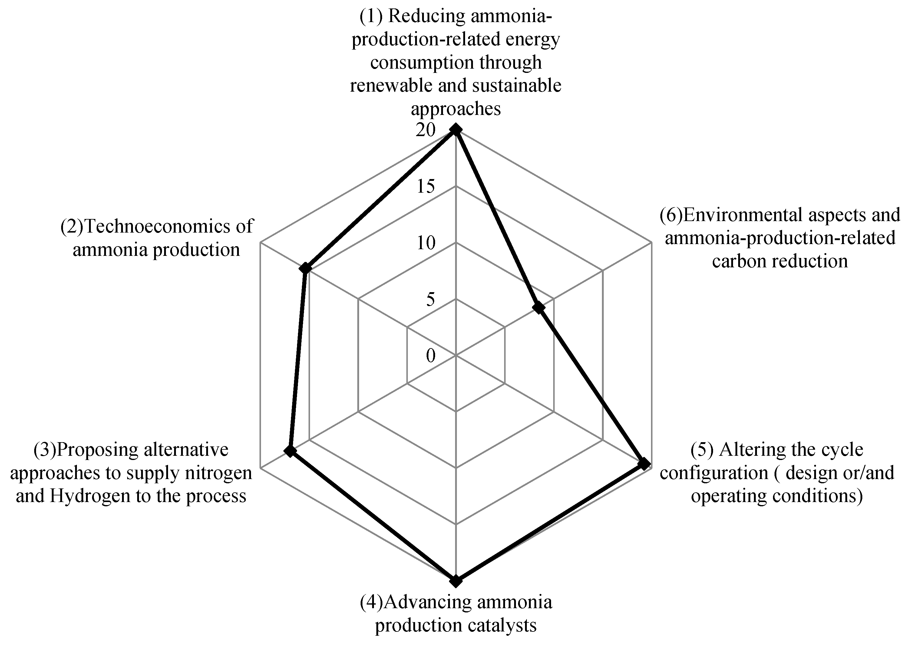
| Category | References |
|---|---|
| (1) Reducing ammonia-production-related energy consumption through renewable and sustainable approaches. | [51,52,53,54,55,56,57,58,59,60,61,62,63,64,65,66,67,68,69,70,71,72,73,74,75,76] |
| (2) Techno-economics of ammonia production. | [77,78,79,80,81,82,83,84,85,86,87,88,89,90,91,92,93,94,95,96] |
| (3) Proposing alternative approaches to supply nitrogen and hydrogen to the process. | [97,98,99,100,101,102,103,104,105,106,107,108,109,110,111,112,113,114,115,116,117,118] |
| (4) Advancing ammonia production catalysts. | [119,120,121,122,123,124,125,126,127,128,129,130,131,132,133,134,135,136,137,138,139,140,141,142,143] |
| (5) Altering the cycle configuration (design or/and operating conditions). | [144,145,146,147,148,149,150,151,152,153,154,155,156,157,158,159,160,161,162,163,164,165,166,167,168] |
| (6) Environmental aspects and ammonia-production-related carbon reduction. | [169,170,171,172,173,174,175,176,177,178,179,180] |
Publisher’s Note: MDPI stays neutral with regard to jurisdictional claims in published maps and institutional affiliations. |
© 2022 by the authors. Licensee MDPI, Basel, Switzerland. This article is an open access article distributed under the terms and conditions of the Creative Commons Attribution (CC BY) license (https://creativecommons.org/licenses/by/4.0/).
Share and Cite
Amhamed, A.I.; Shuibul Qarnain, S.; Hewlett, S.; Sodiq, A.; Abdellatif, Y.; Isaifan, R.J.; Alrebei, O.F. Ammonia Production Plants—A Review. Fuels 2022, 3, 408-435. https://doi.org/10.3390/fuels3030026
Amhamed AI, Shuibul Qarnain S, Hewlett S, Sodiq A, Abdellatif Y, Isaifan RJ, Alrebei OF. Ammonia Production Plants—A Review. Fuels. 2022; 3(3):408-435. https://doi.org/10.3390/fuels3030026
Chicago/Turabian StyleAmhamed, Abdulkarem I., Syed Shuibul Qarnain, Sally Hewlett, Ahmed Sodiq, Yasser Abdellatif, Rima J. Isaifan, and Odi Fawwaz Alrebei. 2022. "Ammonia Production Plants—A Review" Fuels 3, no. 3: 408-435. https://doi.org/10.3390/fuels3030026
APA StyleAmhamed, A. I., Shuibul Qarnain, S., Hewlett, S., Sodiq, A., Abdellatif, Y., Isaifan, R. J., & Alrebei, O. F. (2022). Ammonia Production Plants—A Review. Fuels, 3(3), 408-435. https://doi.org/10.3390/fuels3030026